In the compositor, I have managed to create an XYZ image then convert it to RGB using REC.709 primaries, but I’m not sure how to apply an OCIO transformation to the compositor result instead of do that in nodes. Does having REC.709 primaries cause some colours to be out of gamut upon doing the spectrum>XYZ>RGB transformation, or is my understanding flawed there? If it does, having an OCIO transform take care of the XYZ>display transform would retain the strong colours that are present if using single wavelength light-sources, etc. (though, this does mean any actual compositing that is done in the result would be done in XYZ space, rather than a more familiar RGB space)
I also have not yet implemented any method to adjust the target illuminant, so scenes lit with the ‘wrong’ illuminant (anything other than D65) currently won’t display neutral colour.
But I can proudly say I now have an entirely Blender workflow, even though it isn’t particularly smooth at this point. With some pending changes (I hope) in 2.8, this workflow should not only be reasonably usable, but completely automatic. It would not require using the timeline to represent the different wavelengths (if the wavelength can be a property of the render layer), and doing an ‘image’ render would then render all spectral bins before processing the output in the compositor.
Here’s the node tree that takes the multilayer EXR (in the future, this can hopefully be the render result custom layers) and processes the XYZ then RGB data from it.
In Blender, seeing as how we don’t have a damn OCIO node yet, you tag the buffer itself. That is, if you created a 32 bit float buffer with XYZ data, you’d tag it as “Spectral XYZ” or whatever the title of the transform is, and inside the transform stanza you’d place that transform I listed above, with a to_reference heading. OCIO will calculate the inverse. This would effectively mean that when the compositor “sees” the buffer, it would take the 32 bit float XYZ to_reference via the transform, and yield RGB in the reference.
Yes. All out of gamuts essentially are encoded with one channel with a negative value. Compositors need to take care when doing calculations on such data.
Not sure what a “strong colour” is here, unless you mean simply that the colour is out of the reference space’s gamut and cannot be encoded correctly. Clipping negative values here yields REC.709 values that are in-gamut, and should be entirely fine. This is equivalent to an absolute colorimetric gamut mapping, where the white point are essentially chopped down to the destination volume.
If you are meaning that your imagery has some rather neon-glowing colours that are somewhat posterized due to strong spectral effects, this would require some fancy gamut mapping to negotiate. You’d need to wait for OpenAgX to have that facet in the transforms, but no idea when I’ll get more time to chisel away on it.
You can’t change this. Any additive RGB encoding colour space will always have a reference illuminant, and all values are shifted according to that. Such reference colour illuminant would be typically encoded to R=G=B.
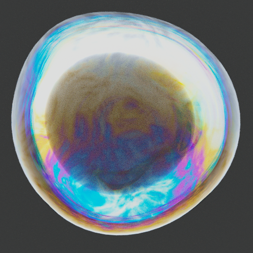
@smilebags It seems your screenshot of the bubble / glass has a low dynamic range rendering transform and is posterizing along the intense regions? Is it rolling through Filmic or just the generic sRGB OETF? This too will contribute to posterized colour regions where your colours are escaping the camera rendering transform and skewing towards the destination RGB’s colour space pure magenta, yellow, and cyan combinations.
Where are the options to do this? I can get the compositor result to give me XYZ data, and I’d be interested in getting that working.
Yep, I just meant highly saturated colours, so out of gamut. Clipping negative colour values will perform a crude gamut clip, and if desired, the compositing can take advantage of the extended gamut if desired.
So, this is in creative freedom territory rather than strict colour management territory? Lets say I illuminate a scene with lights with a candle’s emission spectrum, and I want to make perfect reflectors in the scene look white, do I just push and pull the RGB channels until they match, or is there a more correct way to correct ‘white balance’?
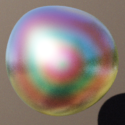
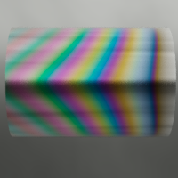
You’re right, that was using the sRGB transform. Here it is through Filmic. Though, I feel in this image, my calculations of the interference might have been off, too.
In 2.79 etc. it is in the Properties panel of the UV Image Viewer. Press “n”, pull up the buffer in question, then select the appropriate set of transforms from the colour space drop down.
It is worth noting that there are two types of overly saturated colours, one attempts to represent the proper colour in question, the other is a distortion and broken colour.
In the first instance, we have the absolute colorimetric volume clamp. This essentially means “The colour cannot be accurately represented in the destination so here is the closest representation achievable.”
In the second instance, it is a byproduct of broken output colour light ratios due to the camera rendering transform. Any colour that hits the limit of a goofy camera rendering transform, such as incorrectly using something like the sRGB OETF to transform scene referred colours, will ram past the rendering transform and the colour ratios end up skewed. This yields the familiar pure magenta, yellow, and cyan skews from colours in skies, skin, trees, etc.
I’d suggest it is strict pixel management science territory. You can only have one adapted reference point in a given scene, and with that, all colours are adapted according to that reference point.
There’s a more correct way.
In this instance, we might have a small candle with something around 2200 degrees Kelvin in terms of a rough temperature. If you wanted your reference space to be 2200K, and as such, that colour ending up R=G=B, you’d simply assert that all colours that are input into that reference space are relative to your 2200K reference. For example, if we took an asset in that was REC.709 based with a D65 reference white, we’d adapt that input to the reference space primaries such that the D65 reference R=G=B ends up R!=G!=B in the 2200K reference space. The resultant white would look extremely blue biased relative to the 2200K reference space white we established.
If we dumped those values direct out to an sRGB display, they’d be rather wonky. The display output would be assuming that the encoded 2200K RGB values were D65, and display them “as is”. That ends up with a broken output as the lights in a reference sRGB / REC.709 display will display D65 when R=G=B. What would need to be done to view the image correctly is to have a camera rendering transform that converts the 2200K reference RGB values out to the display’s D65. This would result in the candle 2200K light emissions to end up R=G=B and displayed as D65 light, but with the other values chromatically adapted to the D65 output. If you wanted to actually display the 2200K reference lights relative to the D65 output, which essentially would look extremely tungsten / warm, you’d simply dump the reference 2200K RGB directly to XYZ, then go directly back to D65 REC.709. This would leave the RGB coordinates “as is” in absolute colour science terms, and display it “as it was” in the reference, with the portions of the frame that had D65 encoded values displaying as R=G=B.
Ha. This too looks a little busted. I’d need to see your transform to properly diagnose what you have going on here. My spider sense tingles a bit when I see large swathes of cyan, magenta, and yellow…
In theory, if you have an XYZ buffer and tag it as outline above, it should Just Work™.
I agree, though if you look at what bubbles look like, they do have a lot of a few specific colours, namely a bronze-ish colour, deep blue, cyan, magenta, and green. I know my math for the thin film isn’t correct, but the colours it produces should be.
I feel this is the last part of the puzzle for me to understand, I don’t fully ‘get’ this yet. Though, I do like that if the screen is calibrated, this workflow should produce the ‘right’ colour on screen for any spectrum. I feel like that’s a little gold sticker I can give myself. If I have a candle next to my screen, the colour coming from the real candle and the screen should look pretty similar, barring for the bad colour reproduction index of computer screens.
Remember that no matter what combination of RGB is input, it always results in a colour. That is, forget the ideas about “white” and even to a degree, “black”.
If you fully understand this, you can immediately realize that R=G=B doesn’t mean “white” in some absolute sense, it simply means another colour. That colour is the achromatic axis that we are assuming we are adapted to. It is still a colour in colour science terms.
What we can glean from this is that no matter what colour space we are talking about, any case where R=G=B will equate with a colour just like any other set of ratios of light. The question is, what colour does R=G=B equate to?
In D65 REC.709, that colour is a specific colour with CIE chromaticity coordinates x = 0.3127 y = 0.3290. Given adaptation time, we call this colour “white”.
So going back to our warmer candle situation, if we were to render a candle using some spectral magic, that colour might end up being around 2200 degrees Kelvin. This, if we convert the Kelvin into a CIE XYZ coordinate, would end up being an RGB triplet when we convert it to some destination colour space. If we convert the XYZ values to sRGB / REC.709 based primaries with the D65 achromatic colour, that candle will end up looking extremely orange tungsten.
If on the other hand, we perform a chromatic adaptation on our candle to adapt the 2200K ratios to be the white of our destination, which is D65, then the 2200K values will end up R=G=B in our D65 output. All of the other colours in the frame of course have also been adapted. If we were to compare a scene with our candle and a pure D65 point also in the frame, in this example our 2200K candle would end up with R=G=B adapted output, but the D65 source that was in the original spectral scene would now be adapted such that it ends up with a much larger bluey colour ratio.
Thank you for that explanation. I feel like I can still become more familiar with white as a colour, but I do understand that adapting one colour to be the R=G=B of the scene will shift all other colours too (including what was considered white) to something else. This is why photographing with different light sources in the scene can be tricky to balance.
What I don’t understand is how to convert, for example, a purple when the white is x = 0.3127 y = 0.3290 to look correct when the white is then shifted to a new xy coordinate.
I have read up about chromatic adaptation and it is starting to make sense.
It involves transforming XYZ into LMS, and then scaling the source white point to match the destination white point in LMS space, followed by a transformation back to XYZ. What I can’t find is a definitive XYZ to LMS conversion, or if one even exists. My ideas for chromatic adaptation is to create a AdaptFromD65 node group which takes XYZ data and a D65 white point, and gives out LMS values, then another set of node groups such as AdaptToD50 which will take in LMS and give XYZ out. How to implement this is currently evading me.
Yup, you can use it to mix glossy shaders with other materials or, alternatively, depending on the material, it could just be used as color in a glossy shader. In the case of mixing it with a rough glossy shader, the thin film would probably be the equivalent of a colored clear coat effect. I think we can imagine it as some rough glossy surface with some other material deposited on it, the substrate of the films. Now, that material deposited on it is not thin enough to exhibit any interference effects, but there are films on top of it that do.
And here is where I realize my mistake. Let’s say we had a metallic film on some glass. Because It’s a metal, some light will be absorbed by the film. That would mean that the reflected and transmitted light do not add to 1, instead it’s R+T+A=1 (where A is light absorbed). If we simply use R as the mix factor for the material in that case, it would mean we are letting T+A pass through as T instead of T only as T. Really, the material should be done in the first way I described (provided there is absorption in the film). Sorry for that!
It really depends on the material the user is trying to create. There could be dielectric films on metallic substrates, metallic films on dielectric substrates, combinations of dielectric and metallic films, and so on. It could be possible to have user built stacks to allow them to optimize the material for whatever combinations of films and substrates they want, but it would likely be very user unfriendly or too much work.
The general solution is to program it for metallic films and substrates since dielectrics can simply be considered by setting the imaginary part to 0. And transparent materials are dielectrics with a refraction/transparent shader mixed in instead of a diffuse shader.
Something I don’t do in my node group that could be done here to speed it up is to assume the surrounding material always has a real IOR.
Currently, I am making a comprehensive, hopefully easy to understand, list/guide of formulas associated with thin-film interference that I found while researching and testing different implementations of it. Look forward to it soon!
I am certainly looking forward to that! I’m of the opinion that a base implementation should make no assumptions and be extensible at the expense of being very complex, so that then you can create more specific shaders by pre-specifying some values and exposing fewer.
I don’t understand how metallic substrates or films differ from other types of substrate or film, but it seems like a metallic implementation can be used to create the other types (by setting imaginary IOR to 0 etc). Is this the case? Could I make a thin film uber shader which can then be wrapped around in simpler interfaces?
I created a chromatic adaptation node which takes in the XYZ coordinates of the reference whites in source and destination space, and the XYZ of the colour to adapt. It is extremely slow, but seems to work correctly.
Is doing matrix multiplication going to be faster if using colour mix nodes rather than math nodes?
Here’s the adapted image from above, coming from D50 to D65. While I don’t think this is the correct adjustment for this image, I feel that it is working.
Use the spreadsheet above and compare values. You should not be doing the adaption in nodes, but rather via OCIO.
Make sure you have a clear means to test with correct values. A random image is just rubbish. Use known testing values and evaluate. Otherwise, garbage in is garbage out.
It seems I can’t do adaptation in OCIO since the place to tag the image for OCIO is completely missing in 2.8 (which is the only version I can use right now due to a graphic card issue with 2.79)
I will certainly need to do some proper verification, since eyeballing it, as you said, will just result in rubbish.
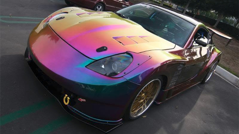
In my image, as the angle becomes more glancing, the colour goes from blue through wheat to purple. On the car it goes from blue/green, through purple, to wheat. Is there any valid way how that would occur if my model is correct? @JettG_G