Hello.
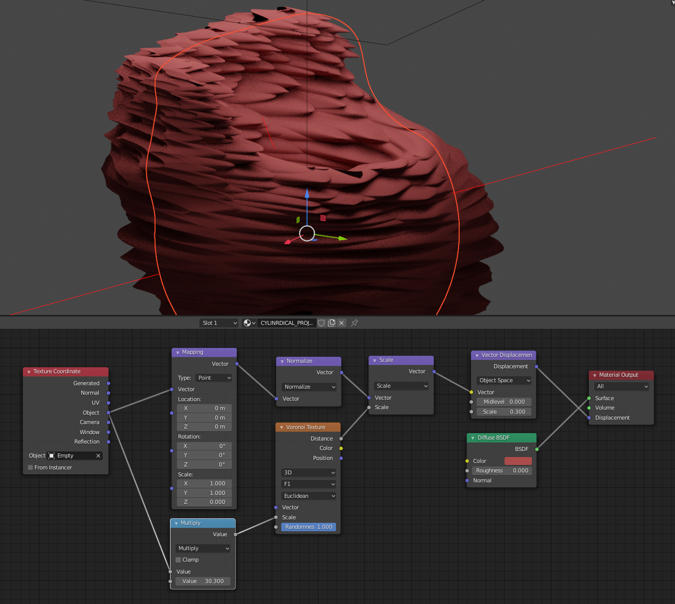
I’m trying to set cylindrical mapping for voronoi displacement on non-cylindrical mesh. In another words ‘switch off’ one of the axis in projection.
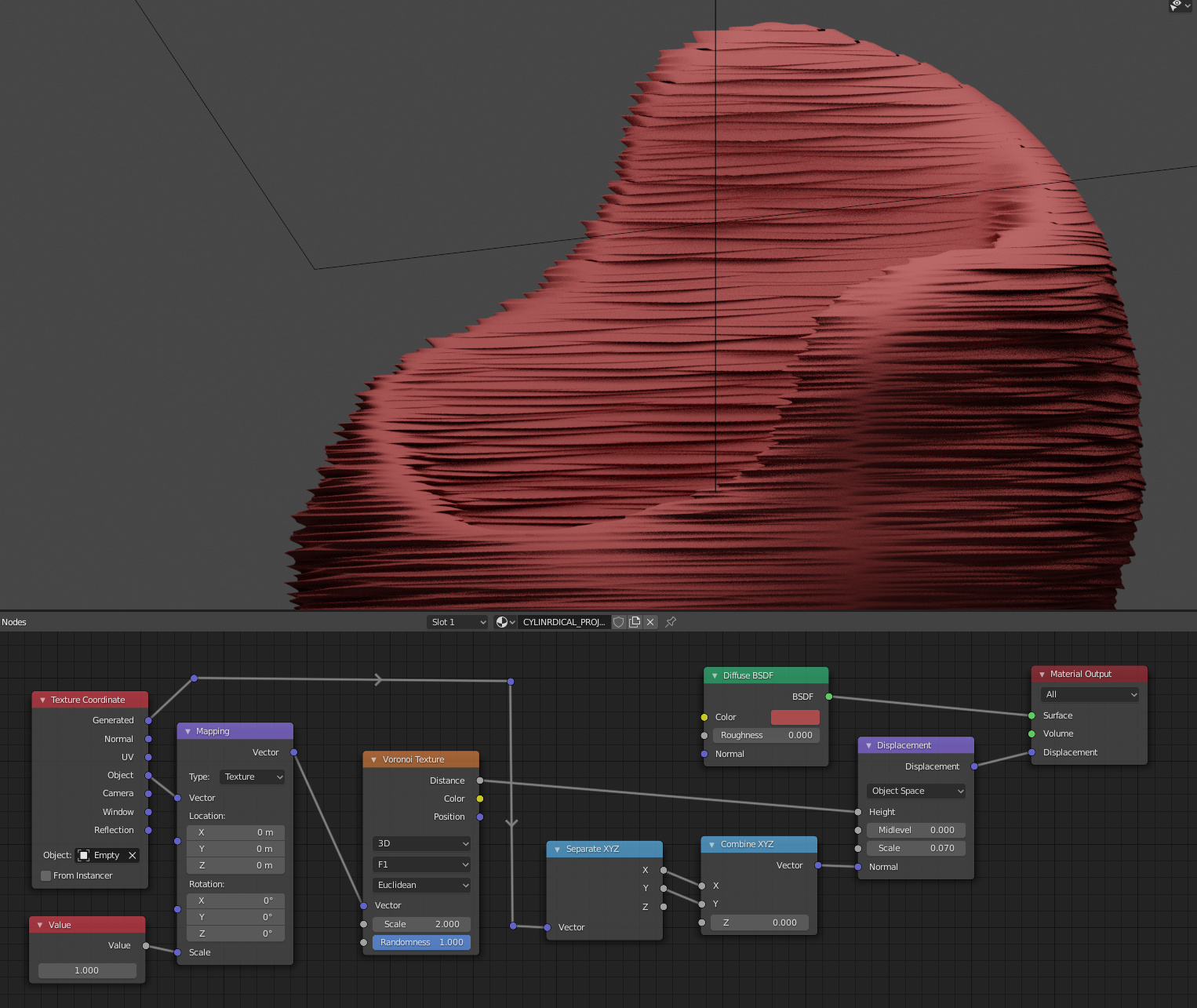
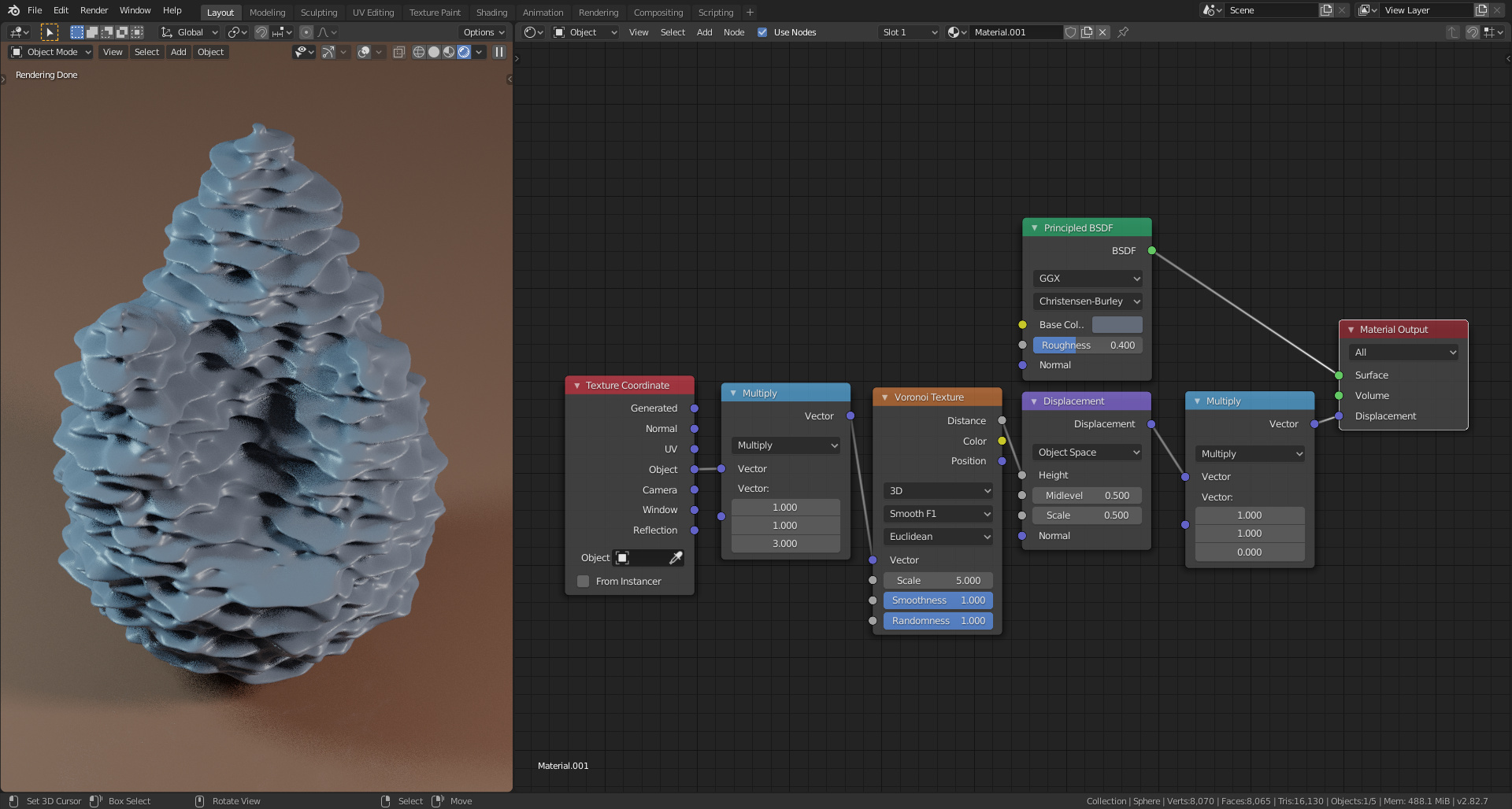
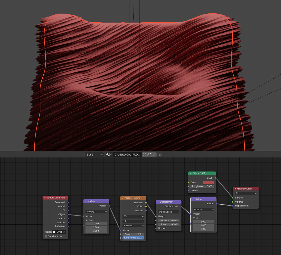
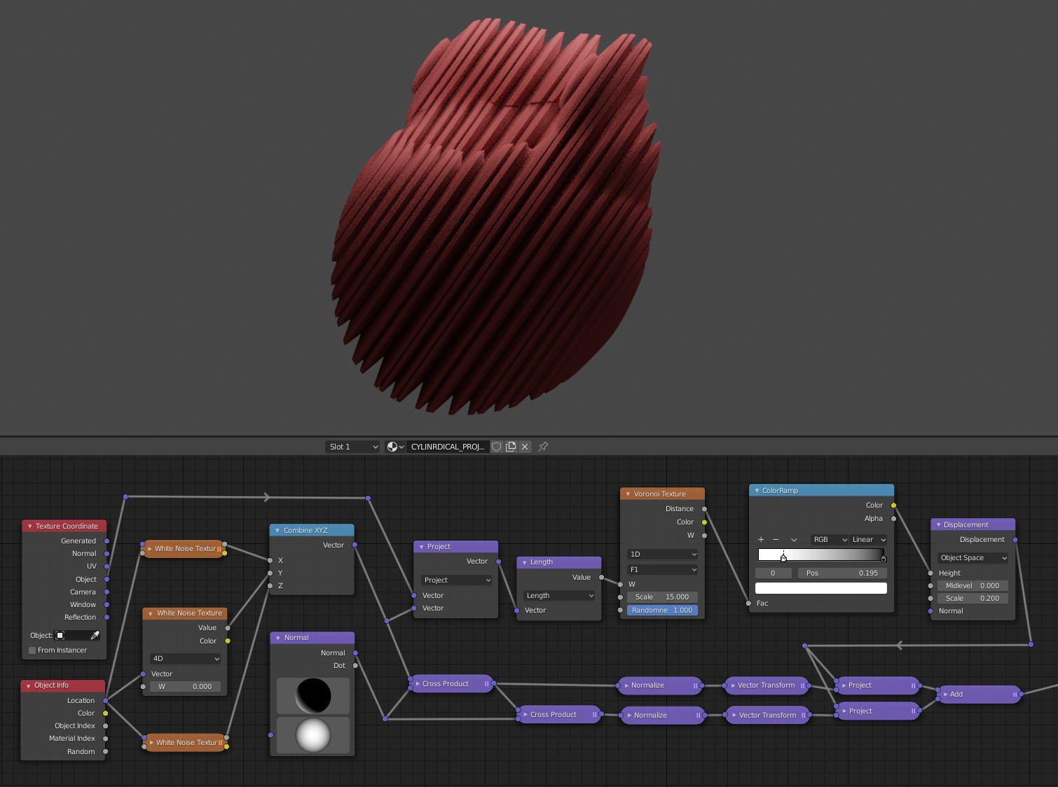
Top is default mapping and what I want is at the bottom:
I’ve tried method from the following thread, but it doesn’t work and leaves seam, so it’s no use:
Tested without much effect trick with proximity displacement form the following tut. Tried scaling z-axis of empty, also using cylinder without caps instead of empty.
Appreciate any help.
Edit: That is pretty close, but still there are seams between two projections. And big displacement scale values are giving artifacts there.
Thank you.
I didn’t use Vector Displacement much, so I don’t know how to control the mapping in it.
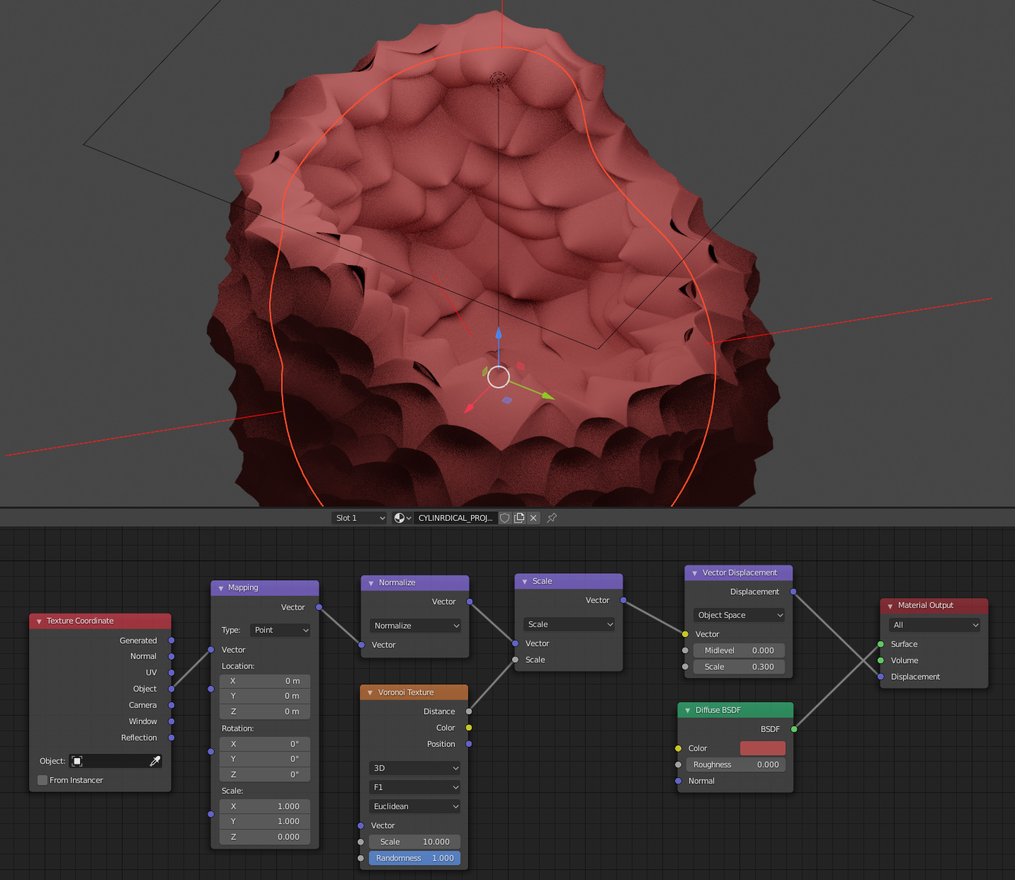
At first glance the result looks like garbage, but maybe it can be refined:
First. The horizontal direction seems to be ok, but the displace is pushing one side of the mesh and pulling another. That is unwanted.
Second. I want to control rotation and the scale of the displace mapping in predictable way. With your setup, after plugging control empty to mapping input the displace goes crazy:
The issue is that, with the graph you’ve shown, it’s no longer a cylinder-- it’s two cylinders. You’re pushing away from two different axes, depending on the position of the mesh. The best way to handle this would be to use two different displacements, from offset coordinates, and mix them on the basis of length to the axis, but that’s something that depends on your mesh.
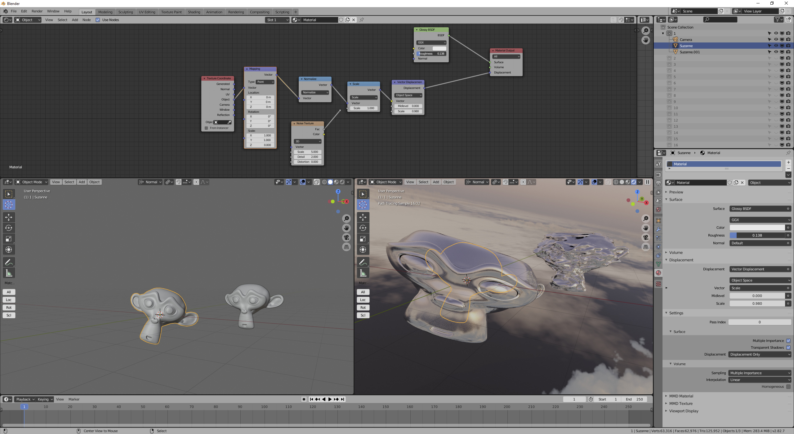
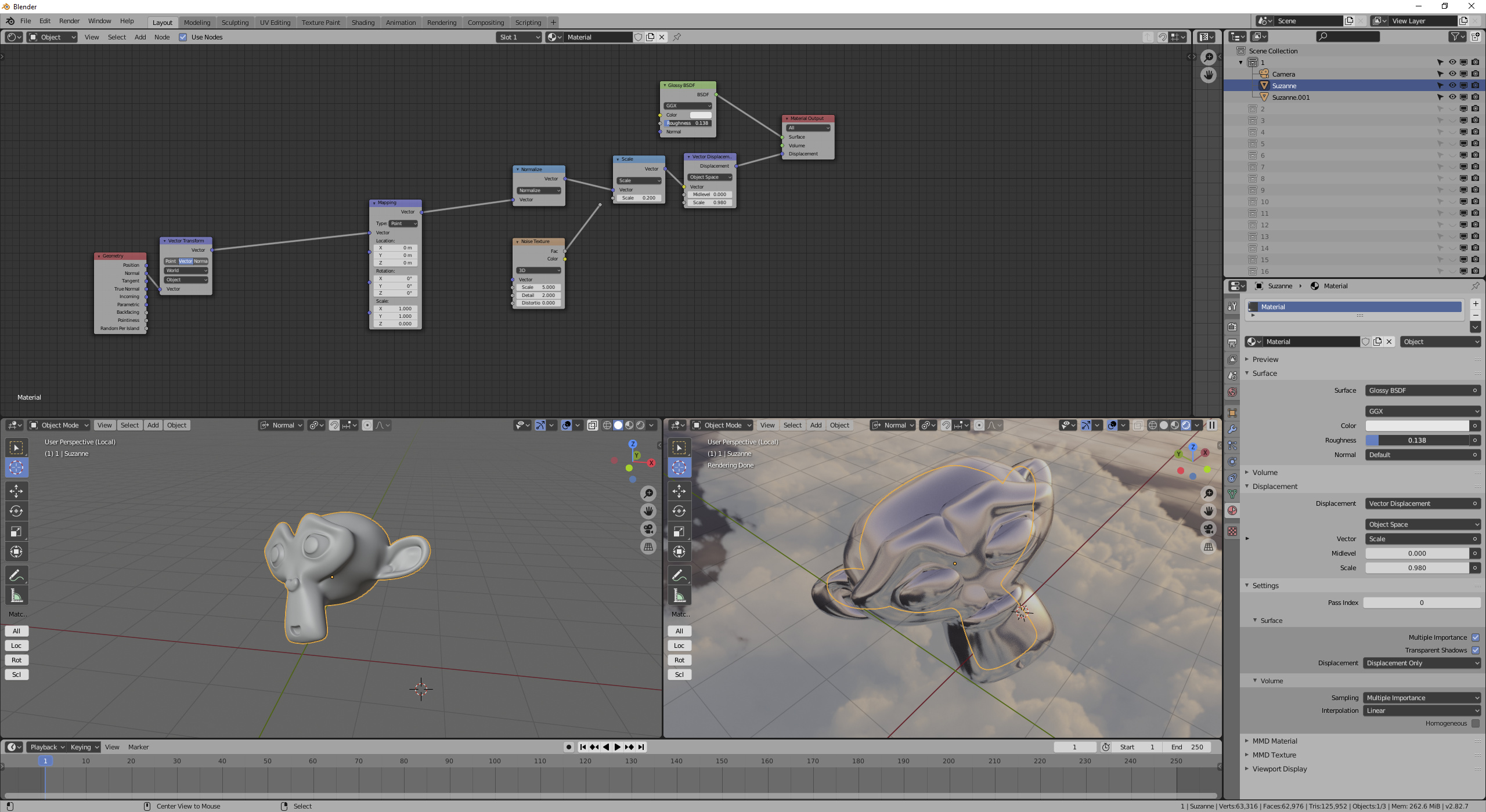
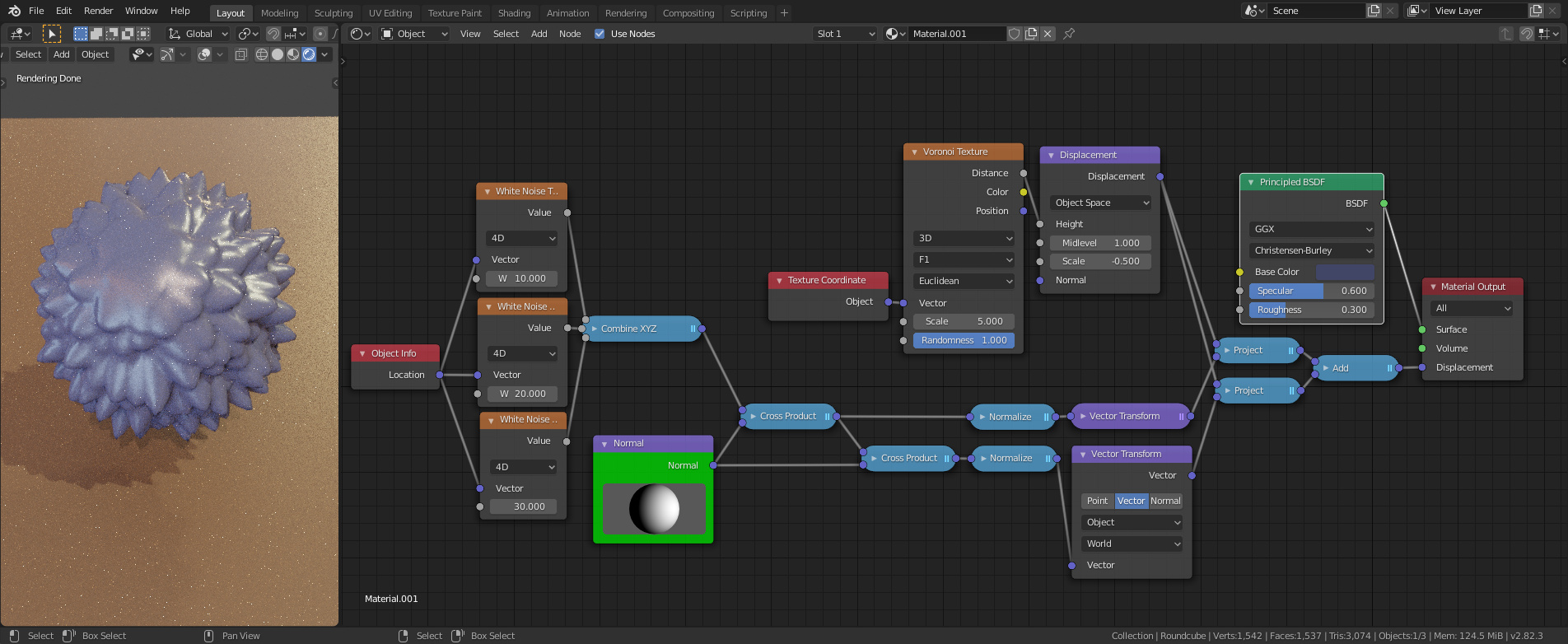
You could discard one object space vector of your normals:
But I don’t think that will do what you’re after. Notice the eyebrows displacing into each other.
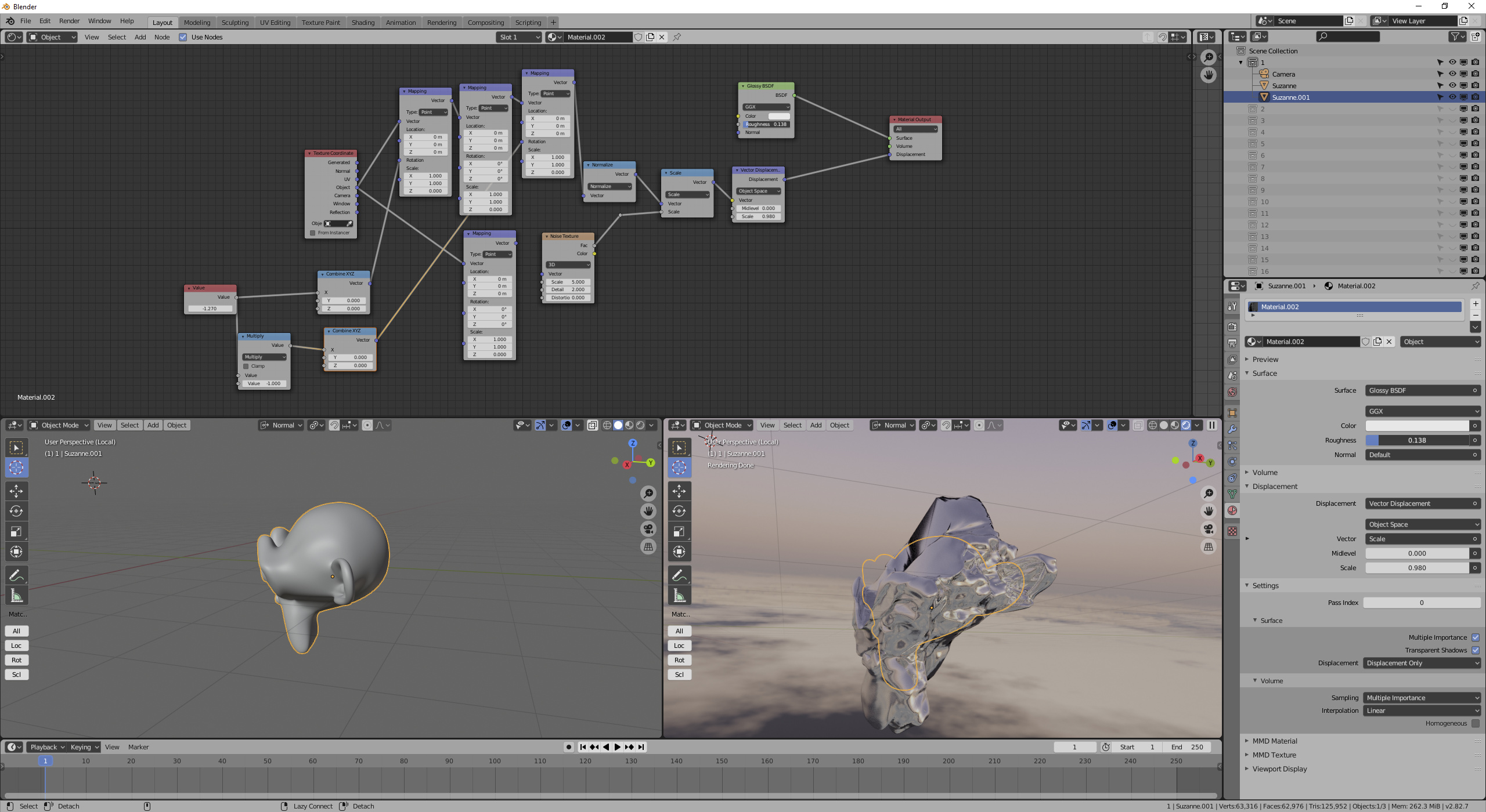
You’re operating in two different coordinate spaces with an empty providing the texture coordinates-- the local space of the empty creates the coordinates, but then you’re evaluating the vector in the local space of the object. Unfortunately, Blender has no node to transform vectors to world space for an arbitrary object. If you want to change the axis of the cylinder, rotate the object coordinates before scaling, and then undo that rotation after scaling:
You can drive that value node with anything you want; you can do the same thing with Y rotation if you want.
If you want instead to change the center of the cylinder from which you’re displacing, all you need to offset the location of the object coordinates with a mapping node.
Thanks for clarification. I might used the term cylindrical wrongly here.
Better would be bi-axial? I’m not an English speaker.
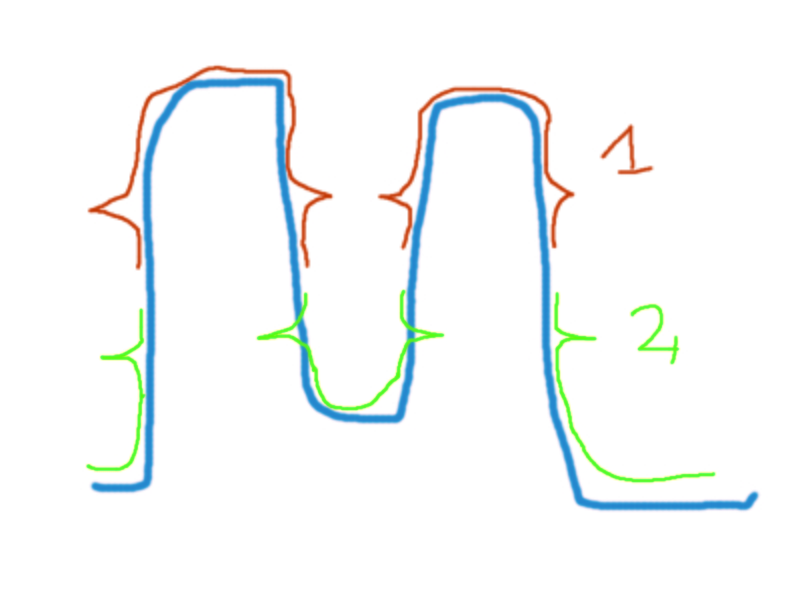
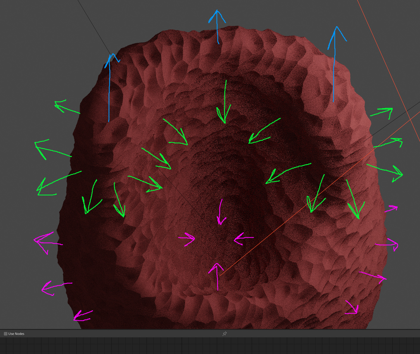
Consider the following. Green and pink are working in both X and Y axis but on different elevation. Both are able to displace any mesh consitently either inwards or outwards. The crossection in the green working plane would be ‘C’ shaped, pink - would be ‘O’.
In blue you can see Z axis direction displacement which I want to switch off.
When I look at your latest picture and the description you offered (no blue arrows!) then what it looks like is what you’d get with the nodes I demonstrated for “discarding one object space vector of your normals”-- the first picture in my second post of this thread.
I think it would be easy to have a not-quite-correct intuition about the problem, that made one think that one solution would extrapolate to some other problem when it wouldn’t. So if you’re working with some simplified version of the problem that you think will generalize to some other mesh, I’d be careful.
This is fu*ing voodoo black magic. If there is anything I didnt get any grasp on in 3D it’s this Vector Displacement thing.
Aside from having some math skills, are there any good learning materials you recommend for a beginner in this topic?
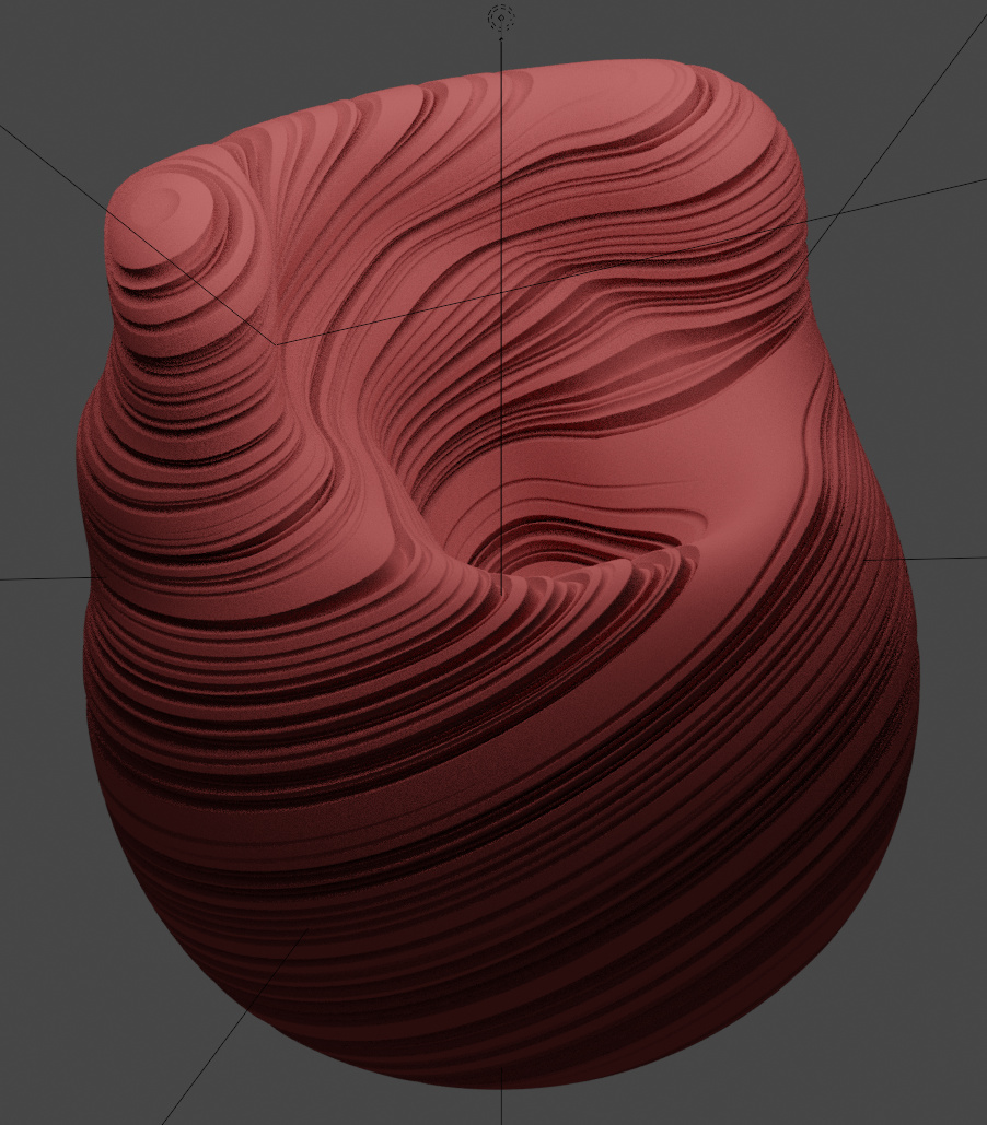
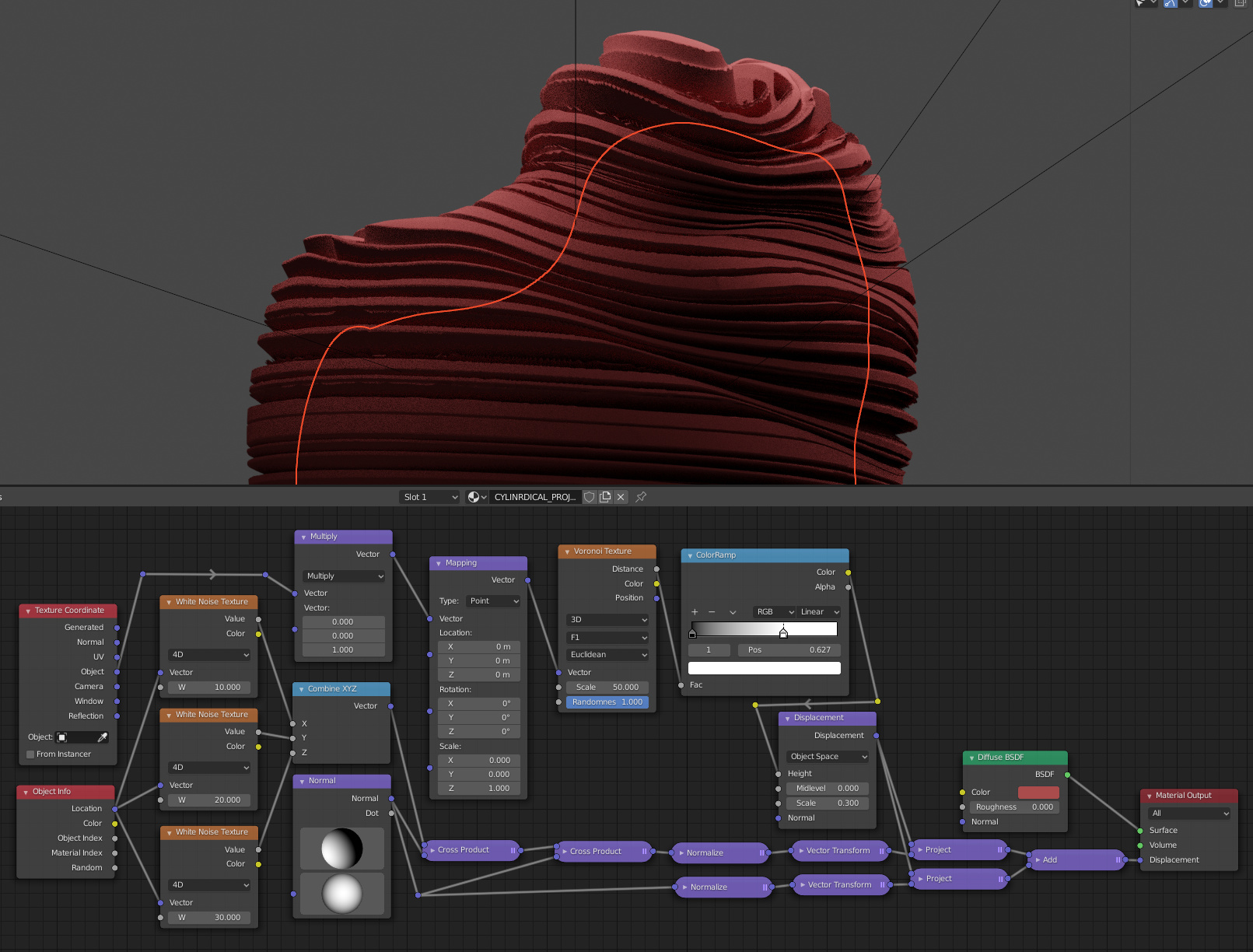
I have completly no idea what I’m doing at this point, but it starts to look ok-ish:
All it’s doing is moving the vertex in the direction you specified. It’s not magic. The direction you specify is a vector (in tangent space, object space, or world space, as set by the vector displacement node.) It’s exactly the same as just selecting the vertex and adding the number to its location.
I guess addition is math though.
I think you’re thinking in terms of faces, when what’s being displaced are vertices. The face angle is set by the difference in your voronoi look up, because that’s what controls how much different the displacement is between adjacent vertices. (Possibly, “virtual” vertices, if you’re using adaptive subdivision.)
It also depends on your original, undisplaced mesh. That’s what should be setting the normals used for some of the displacement. I think. Because displacing them changes the normals. Which is kind of a loop…
But you did a good job with your node group. You seem to understand the concept.
But after plugging empty as texture coordinate object the rotation of the displacement is ok, but the last multiplication is done along displaced object coordinate system, not the one of an empty. How would you couple last multiplication with axis of an empty, because what I’ve tried gives total garbage results?
You need the empty’s matrix for that, which you don’t have.
Perhaps using drivers!?
A less complicated option would be to use the Object’s own orientation, which would let you transform the X and Y axis from Obj->World, and then sum the projections of the displacement map into X’ and Y’.
But that way you loose most of the texture information…
I was thinking more in doing like this below, where the direction is controlled by that ‘Normal’ node:
Interesting approach. How would you tackle the creation of parallel stripes that you can control in predictable way with that node setup?
I can get stripes but thier mapping and displacement direction are decoupled so the control is hard.
Getting the stripes to be parallel and be displaced along a plane that is parallel to them is near impossible I think.
To the bottom Normalize, you should connect the left Cross Product… not the Normal itself.
We need two vectors that are prependicular to that normal vector (and perpendicular to each other) to be used as inputs in the Vector Transform. The Cross(Dir, Randompoint) gives one vector, and the Cross(Dir, Cross(Dir, Randompoint)) gives the other.
For the stripes thing, perhaps it’s better to use a 1D voronoi, and use the Sqr(Dot(objCoord, Dir)) as the coordinate. (removing that Mapping node that’s the culprit for your problem)
edited: because the Sqr clamps negative values of the Dot Product, perhaps a better solution is to use Length(project(objCoord, Dir)).
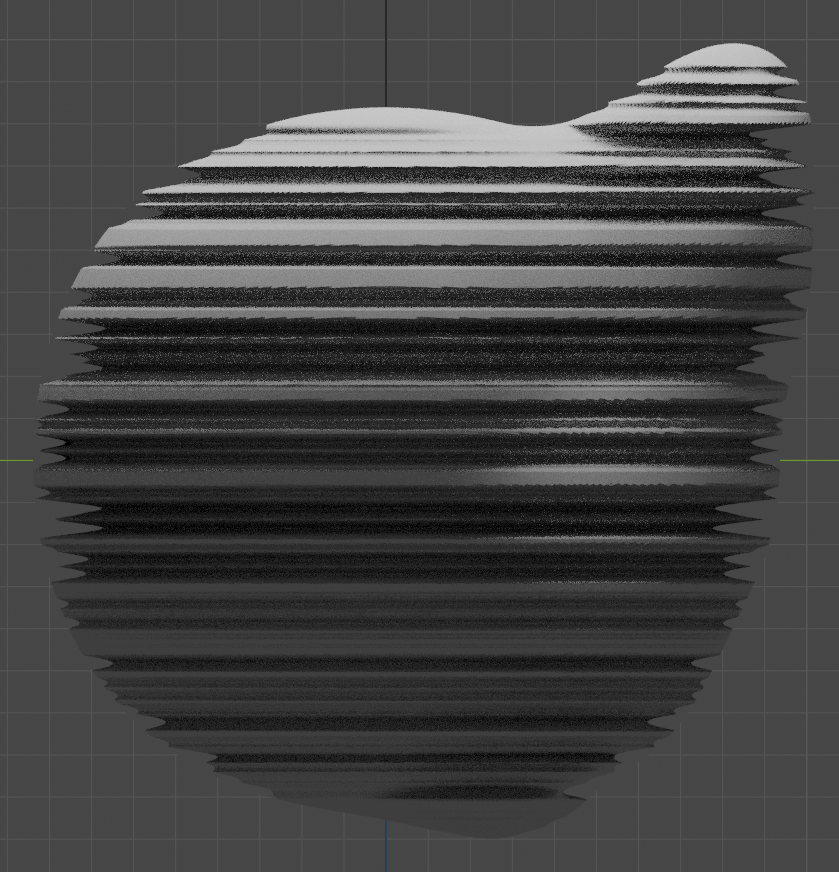
Which means, the final result is close. The only thing out of control is tilting the pattern in right angle.
The three white noise textures IMO are not well suited for it, because when changing their values they give random result. When they are setted to zero thou, the axis of displacement is going through (-1,-1,-1) to (1,1,1).
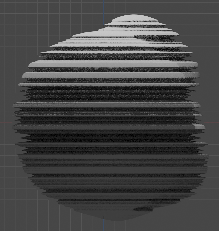
Which means we are in square one. Here is a shot of accual producion file. The white plane is helping giude for adjusting displacement angle:
You don’t need to use the Normal node… I just sugested it because it’s a bit better to manipulate. I’d personally just use a CombineXYZ and input my vector by hand or if it was for a more complex setup, use drivers. Other options include using the Mapping node, or the new RotateVector to spit a new direction.
The important thing is to use a normalized vector.
The 3 white noises are not to touch unless they happen to be a scalar version of the direction vector. In that case nothing will work, and the seed for the white noise should be changed to something else. Also, if the object happens to move, it will also change the random point, so you can also input your own vector the same way I described for the direction vector.
The random point only serves the purpose of defining which direction the Xdir axis would be (since a simple Dir Vector can have infinite possible Xdir and Ydir axis).
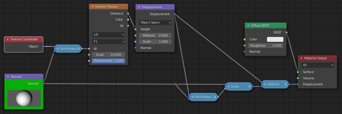
Now that I’m thinking about it, there’s also another way to do something similar, without projecting the displacement to the Xdir/Ydir plane…
If we use the Dot product between Dir and the displacement vector, and then subtract the dp*Dir to the displacement vector, it should also force the displacement to be perpendicular to the Dir vector… might be far less nodes than my setup above.

")