I am new to Blender, but have about 10+ years’ experience in other 3D apps, including Lightwave.
I’m trying to get up to speed in Blender and making simple shapes to get my feet wet.
I’m noticing wierd black areas or splotches that aren’t remedied by the command for making sure normals are aligned.
the obvious guess is that I’m new to blender, yet I can’t see any glaring blunders in my modeling.
Any tips to get me back on track would be appreciated.
here’s a pic of what I’m working with:
on the left is how it looks like in modeling window…a basic cup. at right is a render after hitting F12. the stuff around the perimeter of the base is what I’m talking about.
Remove any doubles (W) and check for any faces that are inside your mesh. Check the direction of normals, don’t just rely on Ctrl+N to recalculate them.
I am fiddling with the modifier “EdgeSplit” and that seems to have gotten rid of the dark areas.
if this is SOP, cool, but I’m still not sure that my modelling technique was OK.
Everything looks proper in wire; is that a good litmus test?
Do I need to still examine this beast to find other errors I could have made? I guess the edgesplit thing is cool but could it be masking actual bad modeling?
No, it’s probably not masking bad modelling. The black bits were probably from Blender trying to smooth out the normals across a very sharp edge. Edge Split simply splits sharp edges so Blender understands they should not be smoothed.
As my skill in blender progresses, are there things I need to be aware of that cause these normals to flip as I am modelling? (if in fact I did flip them)
what I did with that cup was very simple…I began with a cylinder or a circle, and I just beveled out the shape…
after 7 years of Lightwave, I came to know many of the wierd things that would happen and you just know what to do as second-nature…
It doesn’t sound like the normals were flipped in this case (visualising the normals is an easy way to check, then you can recalculate inside or outside, or manually flip them). I believe it is to do with the way the normals are calculated when set smooth is used.
If set smooth is not used (or if set solid has been used), every point on a face has the same normal (at right angles to the plane of the face - the same as is shown when show normals is used). Neighbouring faces have a visible hard edge between them where the normal changes abruptly.
When set smooth is used, the normals are interpolated between the normal of one face, and the normals of the neighbouring faces. If the faces meet at relatively shallow angles, this gives the illusion of a smooth surface. It is only an illusion - the silhouette of the object still shows the planes of the faces. If neighbouring faces meet at extreme angles, the interpolation of the normal has to be extreme - it twists over the sharp edge, trying to smooth it out. This often results in ugly shading, and we usually want these edges to remain sharp any way.
The Edge Split modifier literally breaks the edge apart, causing some duplication of vertices. This prevents any interpolation between neighbouring faces, because they are no longer connected. It’s one way to get a mixture of smooth edges and sharp faces, and very useful.
making edges sharp, is an alternate to adding extra edge loops, because if you add an extra loop to the edge, with the subsurf modifier on, you end up with tiny faces between two edgeloops, and it makes it difficult for blender to calculate the normals.
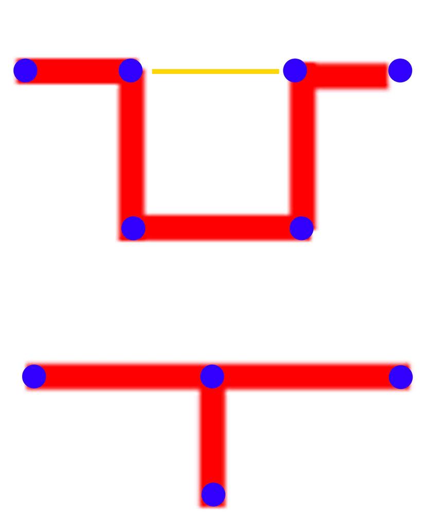
To clarify what theeth said, about the T or U (in your previous thread)
So, here’s a picture to try and explain that,
The orange line, is what you should check for, a non-manifold mesh - faces connected on the inside.
I’ve made a rim before, as a T, like in the bottom section, but you should model things like that with a U shape.
if I’m understanding you correctly, you’re saying that models should be fully articulated and not with shortcuts, but in the case of a bottle or cup, the inside and outside of the cup’s wall should be modelled and if there are rims or flanges, not just make that one thin edge but model the thickness.
and in any case, one surface should never fold onto another surface in such a way that forces Blender to render two or more faces essentially occupying the same space.
Basically yes.
But keep in mind, that not every thickness hsould be modelled
Skin has a thinckness, but because its a closed surface, its fine to have it as one layer.
But for the eyelid, you’d model that rim.
So yeah, you get the point.
There’s also a script, “solidy selection” , that you might wanna play with.
I dont think it would work for rims but keep it mind for future projects.
OK…In looking back on my working with this cup, I might know what the exact issue is. I did what I’d do in LW, but maybe this is illegal in blender.
IIRC, I first modeled in the vertical outside wall, and then the top rim of the cup, the inside and the curved bottom (walls curve to a flat bottom).
then, modeled the base which curves in a little and I noticed that the base had no bottom face, so I cheated somewhat, knife cut just above the bottom ring of vertices, then did a loop select of the bottom ring and scaled them way in, while constraining them horizontally.
that resulted in artifacts even more heinous than in my original post, so I did a couple of loop cuts of concentric rings on my new base face, which I scaled out to the edge of the newly-formed (and perhaps incorrectly-formed) base in order to bolster the edge and lend I guess some flatness to it.
Long story short, I think I needed to have had a way for the base to already have had a bottom face. Instead I tried to make one in a way that might be incorrect in Blender’s way of doing things.
Well there’s a lot of ways to model anything.
There’s a page on the blender wiki thats a great overview of things. http://wiki.blender.org/index.php/Doc:Manual/Modelling/Meshes/Basic_Tools
There’s the spin tool,
or starting from a cylindar and adding loopcuts then resizing,
booleans, (not the best in blender)
Oh, you could also do the rim by painting your own bump/normal map.


 )
)