Good afternoon ![]()
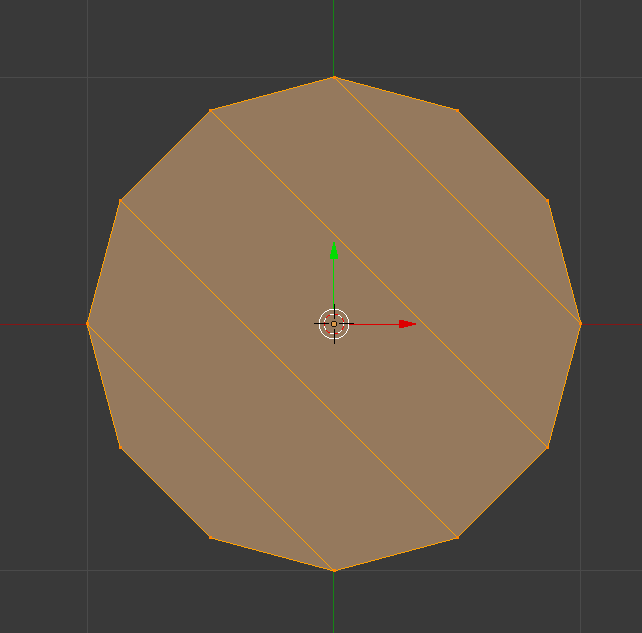
Is this correct, for Blender render?
unless i remember it incorrectly, this is good, yes?
Good afternoon ![]()
Is this correct, for Blender render?
unless i remember it incorrectly, this is good, yes?
What is the purpose of the mesh?
There’s no more Blender Render in 2.8. What do you mean by “for Blender render”?
To summarize - what do you intend to use that geometry for? Subd modelling? Hardsurface? Printing? Rendering?
In general when you have 12 side circle you can fill it in with GridFill and have 9 quads in the middle.
Hey
“Blender render”, I meant that everything in this scene/file will be used for rendering with Eevee, Cycles and Radeon Prorender. (if or when RPR will work with v2.8)
that surface will not be flat, for now I was just doing basics, more of a helping guide for later modeling, as diameters of 15m,6m and so on. It’s a TLOF (Touchdown Lift-off Surface)
I just like to use helping aid, in form of guidelines of models, after that I make/duplicate it or redo it, depending on what i am making. It’s just better to model, when you have a simplified version of a structure/model before you go into detail. You know to get the feeling of a scene/model.
I was just wondering if I connected those vertexes properly, since I went about this in this way. I made a new collection/model by adding a Mesh>Circle (8) and then while in Edit mode I went and added a 15m circle (12) without any fillings (for both)…
Maybe I should try out that GridFill, i use (F) fill a lot, like when i was filling polys, i select 3 edges or 4 depending on the state of the filling, that way I get a properly connected topology, right? I found out that if I don’t fill it properly, like i would not select an Edge when filling I would end up with a funky topology
I hope this wall of text makes sense to you.
CheerZ 
Well, there is more context now however it doesn’t really clarify what is the purpose of the mesh, meaning should it have clean topology vs should it be optimized. Note that helper mesh used by you for some other purposes like reference or whatnot might have any topology you’re comfortable with as long as it’s not used in the final models and isn’t going to be.
That said, if you want to go from 12 sides to 8 then geometry on the screenshot is not bad so far; just make sure to inset it if you’re going to subdivide it so that 5-sided poles aren’t on the curved surface and are moved away from it.
If you meant to obtain all quads from a quasi-circular topology, yes it is
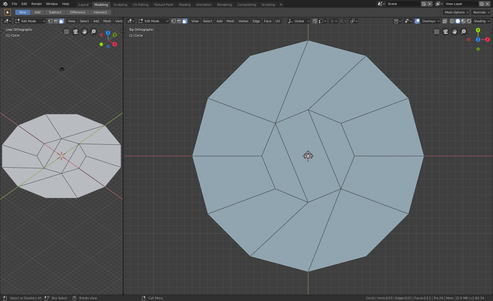
Unless, of course, you want something like this:
Add circle, edit mode, ctrl-f, grid fill, then adjust parameters
What you show should work. However, if you are looking for good practice for the future, there is an easier way. See the screen shot below. Just extrude, [Enter], scale inward, repeat and merge at the center. Then select every other radial line in the center, scale outward, then dissolve them. The result is the minimum number of quads and it’s symmetric. Note that this only works for an even number of sides. I don’t believe it’s possible to have a closed periphery with an odd number of sides that can be filled with all quads. If this is not true, I’d like to know about it.
Ah ah, this is the thing I wanted to do in the first place but didn’t know how. Neat.
Oops! In my previous post, I said the shape on the right was the minimum number of quads–it’s not. The minimum is 6 quads as show in the screen shot here. I’m not sure what is the easiest way to make it. I took one pie shaped quad and spun it 5X over 300 degrees. There might be a better way. 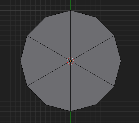
While that is the lowest number of equal size quads, it’s not the lowest number of quads. After all you have a vertex in the middle not altering the shape… lowest possible quads would be:
but this may be less useful for your needs.
Good Point. 
Thank you all for the replies ![]()
I kinda know that i should make a new thread for this but i would like to ask an additional question!
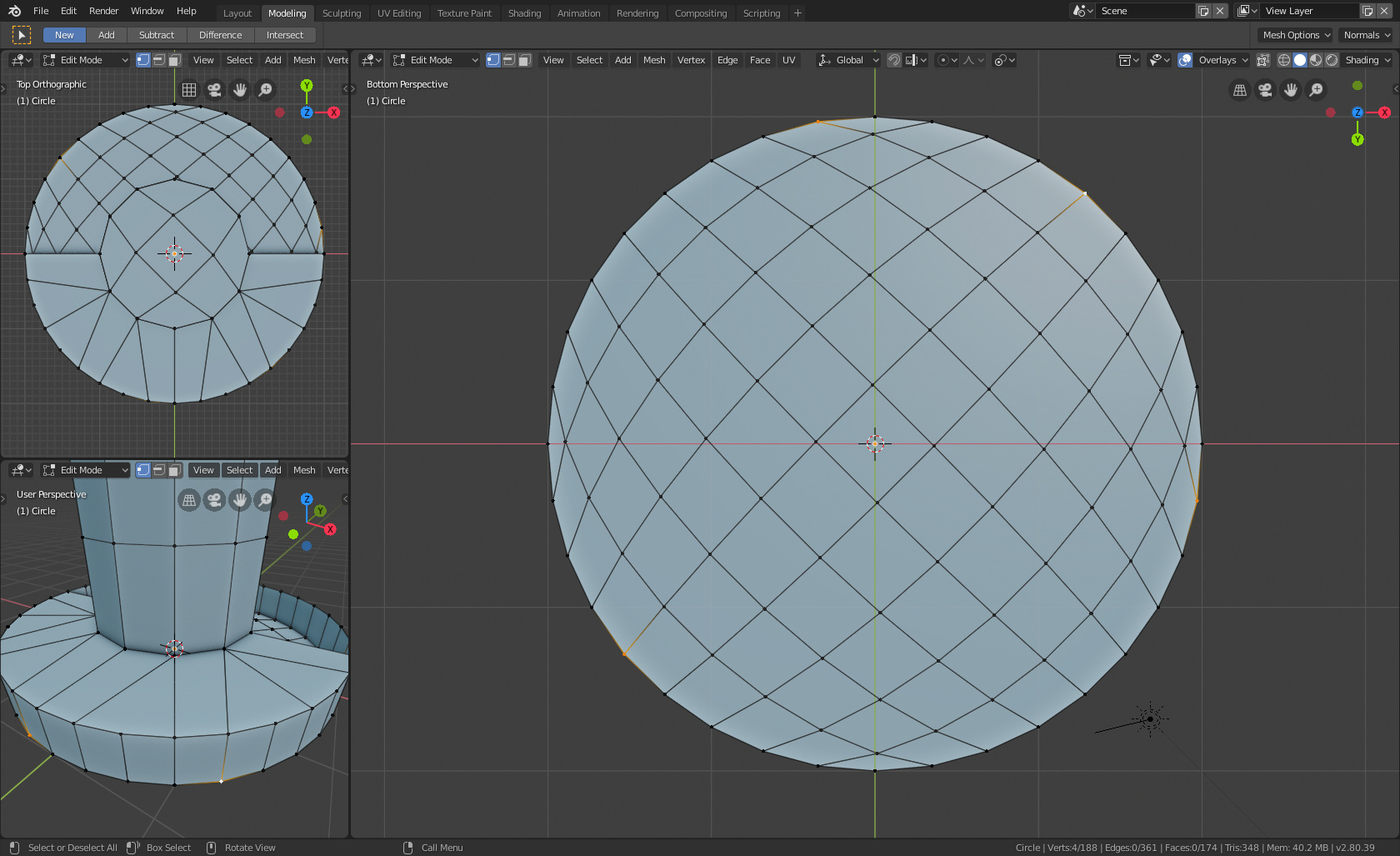
The center top (top left view), middle of the model (8 Verts) is filled with Grid fill
the unfinished filling can probably be filled faster, by connecting 16 verts, that way I will have 4, that can probably work but not the questions i wanted to ask… sorry sometimes i just type what i am thinking off, not sure if it will work…
the question i wanna really ask is
the bottom is filled (32 verts) with Grid Fill, so the thing is its filled but now i would like to straighten the edges, the big view has 4 verts selected X and Y lines, so how i can make tchem to be straight, from one vert to the other? I kinda don’t know. I used to use Wings3D but that was a long time ago, even now from time to time i still use shortcuts that don’t work in Blender and it frustrates me.
Does the top part and the bottom part have to have different numbers of vertices? It’s something that could be done in seconds by using extrude, scale and transform if all the circles could share the same number of points. For filling the very center of flat circles I usually just leave it as a giant ngon. It does no harm
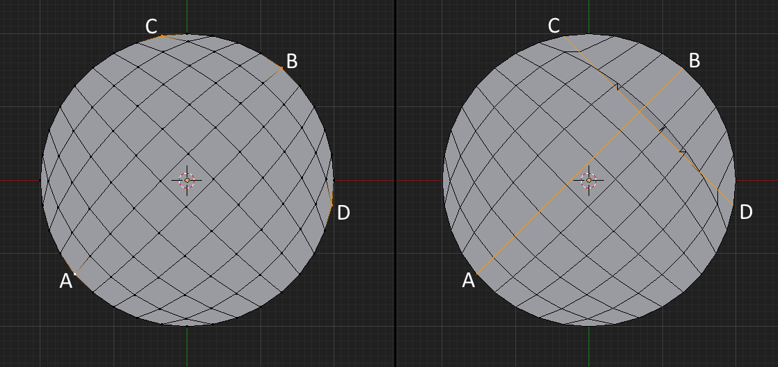
You can make straight lines between the vertices you’ve selected, but straightening one causes problems. Referring to the left half of the first attached image, you can make a straight line between A and B, but creating one from C to D causes some of the faces at the upper right to overlap adjacent faces as shown in the right half.
You can easily simulate Wing3D’s Straighten command as long as both endpoints have the same X, Y, or Z coordinate. Say for example that both endpoints have the same Y coordinate, then select one endpoint vertex, set the cursor to the selection, then (in pivot mode set to Cursor) Scale Y 0.0.
If the endpoints are not equal in X, Y, or Z you can either temporarily rotate the object so they are or rotate the coordinate system so they are. As an example, looking at the left part of the second attached image, assume you wanted to make the vertices between 1 and 2 fall on a straight line. Select the center face, then in the Transformation Orientations panel, switch from Global to Normal. Turn on the manipulator if it wasn’t already on. Next press the plus sign and give the new orientation some name (say “Tmp1”). Then switch from Normal to Tmp1 and move the cursor to the vertex at 1–see the middle part of the image. Now, with the manipulator in Scale mode, move the red handle to the center of the manipulator to scale X to 0.0 and the line will be straight as shown in the right part. This is only one of many ways to do this.