We have recently shifted from Modo+VRay to Blender+Cycles. Overall it has been GREAT. But there are some usability things where I scratch my head and wonder why things are needlessly complicated.
For this problem I wanted to check if it is user error/not knowing enough, or a real usability problem.
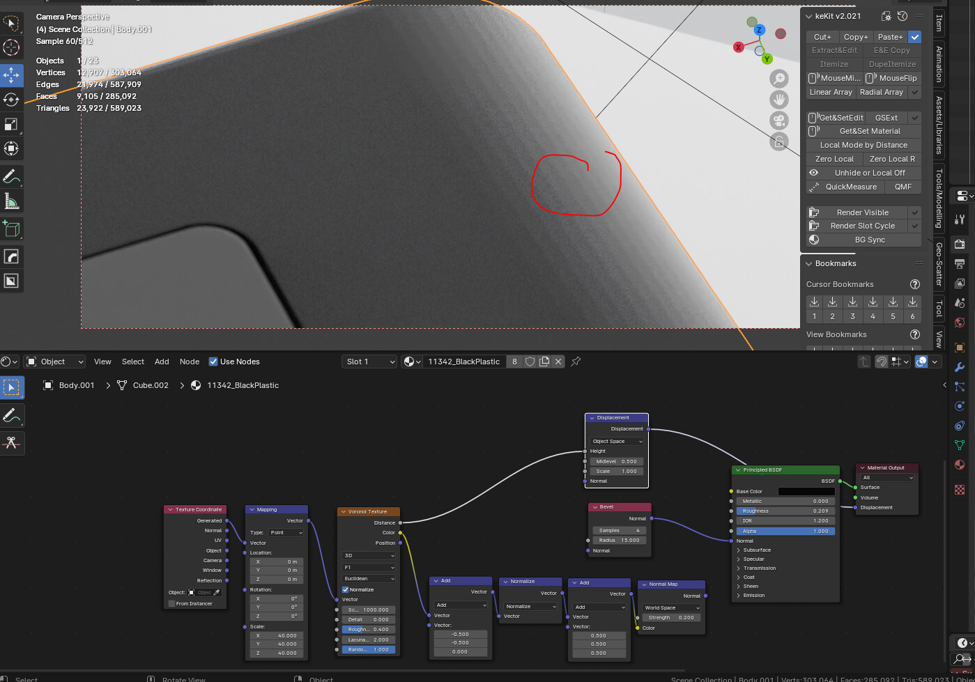
I have a product render with a round corner on which I want to apply a fine structure to simulate rough plastic. In Vray I would have just plugged a prodecural into the bump input. When I try that in Blender (either displacement or bump) I get facetting:
Finally I read that bump mapping is basically not working in Cycles and I need to feed it a normal map. But for that I have to manually convert (with vector math) my color input to a normal space.
Is there an option/node to convert color to normal information? This should be a default option on the normal map node, or at least a standart node shipping with blender…
Just wanted to check if I have just overlooked it and been silly, or if this is really so difficult and convoluted. Reminds me a bit of the whole Mapping issue which I discussed in this topic.
I hope I am wrong, but if this is the suggested solution out of the box, then this is super user-unfriendly.
Looking forward to your feedback and am hoping that I am just not knowledgeable enough and Blender is already doing it right.
Creating normal textures from procedural textures has allways been a bit difficult in Cycles… As sampling is done in tiny fractions of a pixel, the values produced by the procedural textures can vary from sample to sample, making the resulting derivative difficult to converge.
Using the Bump node, one needs to be carefull when choosing the correct distance (the default 1.0, is way too big for a procedural texture; i tend to go around 0.005 but it depends on the size of the height variations). And a strength of 1.0 is also a bit big (a value below 0.5 is normally better).
Another option is to bake the procedural texture, and use the texture with the Bump node. This works quite well, but it’s an extra step.
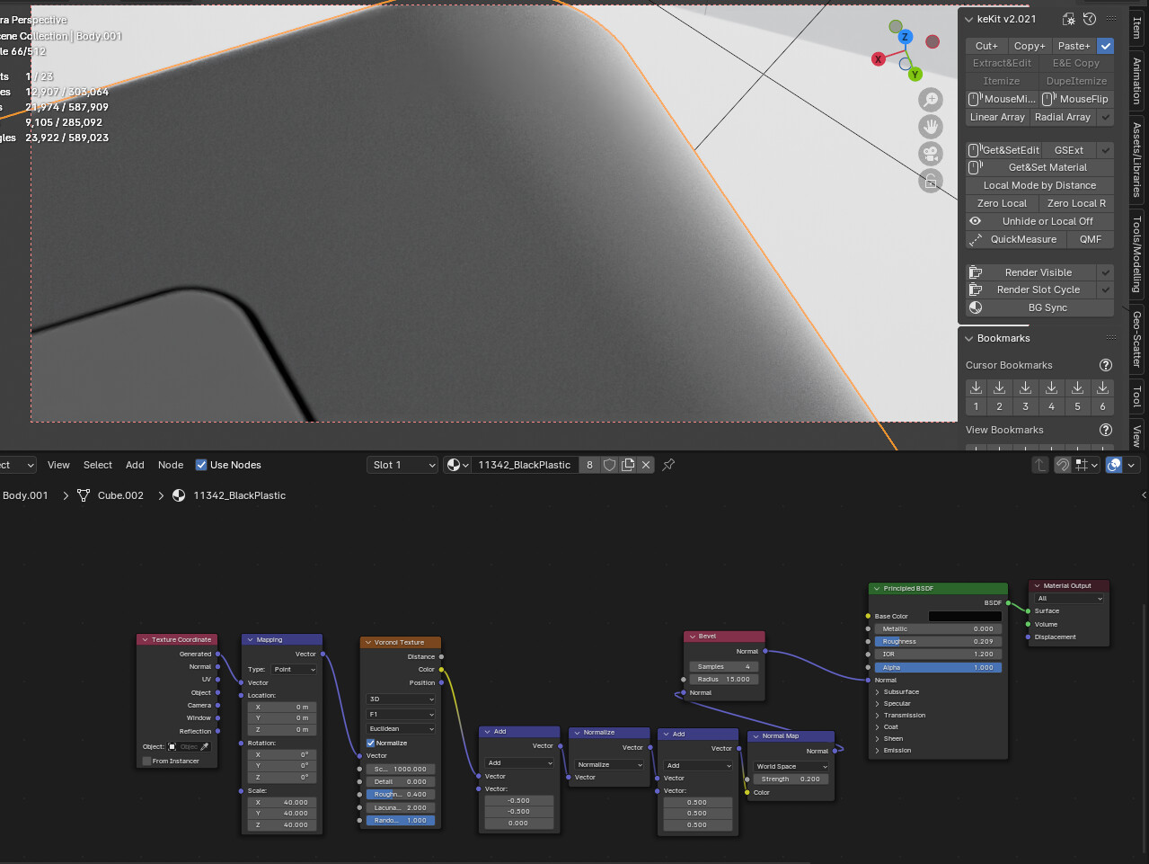
For the NormalMap node, we need a different setup (the one you used)… That’s because the colors from a procedural texture don’t quite represent the encoded Normal vector direction, and a small adjustment is needed (all that vector math), so that the resulting normal vector lands in an acceptable range.
I used a similar construct here (file included), and it’s been my preferable method for years.
As for Displacement/Bump, I never use it, except when I really have geometric displacement.
Thank you so much @Secrop - really appreciate your input and your detailed explanation. I have been brushing up on my vector math recently and I do enjoy it - but while working with a 3D software my assumption is that the software should just take care of these conversions, range mappings etc for me…That some of these basic issues become so complicated is really holding blender back!
Will have a look in detail at your example file - thanks again!