i was trying the other day to recreate this tutorial in Blender “Earth Zoom” which you can find here http://www.videocopilot.net/tutorials.html?id=15
i thought i could get it working but i find myself stopped by Blender geometry scale limit and camera view and location limit . Is there any way to make this work ( maybe with the node compositor ?) … i really try everything but i could not find a workaround .
In the compositor i did not find any way to scale the geometry without scaling the texture too …
the only way i see that this could be made in Blender would be with a wider rang for camera location and view and bigger geometry scale
any idea ?
yes it is very easy to do. I will walk you through the first two, and you can apply it to the rest.
Create two image input nodes, one for each image, just as he did for each channel in AE. Use the time node feeding the Scale node to scale the second image down to match to first, just as he did. You might want to use the side-by-side viewer node to help you line up the relative sizes of the buildings.
Route the output of that scale node to a mix node as the second input, and the first image node directly to the top socket of the mix node. Use a time node to feed the Fac input of the mix node, so that the mix outputs an image fading from top socket to bottom socket.
So, for a given period of time controlled by the Time node feeding the Mix node, the top image will be shown, and then the zooming image will be mixed in. The result appears as if the camera was attached to that weather balloon. enjoy!
I grabbed the image files from videocopilot.
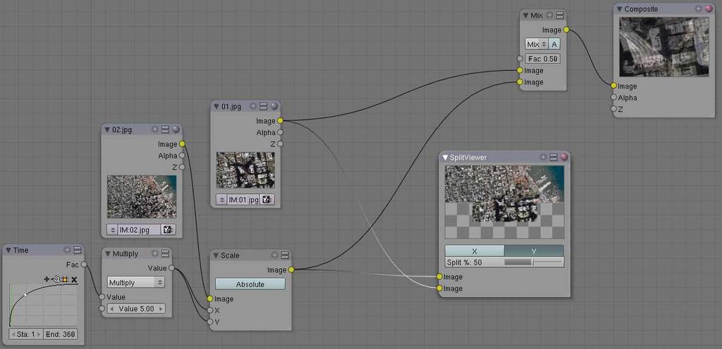
Here is my picture of papsmurf’s node suggestion.
There is a scale problem as mentioned in blender, but this can be overcome by simply adding a math node between the time and scale node.
However, papsmurf, I still get no scaling based upon time using your suggestion. My assumption is that the time node will drive the scale. This does not work, however, when I scrub the timeline, my composite node does not change. It only changes if I edit the curve of the time node.
i still have to get the zoom effect correct ( get a good IPO curve ) and add some rotation and maybe camera shake … the rest can be made with the compositor
the tricky part was the camera clipping start settings which have to be keyed with a value of 1.00 in the first frame and a value 0.001 in the last frame and last i had to use Blender official release because in the SVN version the UV Texture Face pane is broken or not working anymore ( i used UV mapped planes and to be able to make them a bit transparent to line them up in Textured mode i needed the Texture Face options )
so … yes it is possible to make this with Blender ( now i will see if we can also make it with the compositor only … which i still see some problems because it is not the same to line up two images then to line up 7 images … )
Overall, it looks fairly seamless. So how did you handle the feathering of the edges of the individual images (like Andrew Kramer did in the AE example)?
I don’t think it is possible to do in the compositor at this time. There is no “Real” stacking system that I can find. There needs to be a put this layer on top of this layer without mixing colors and obey alpha. The alphaOver node does not seem to work correctly and the mix node does not have a “copy” algorithm.
Image mapped planes was going to be my next approach. So how close together in z-space did you place the planes?
You can keep the camera fixed and the clipping wouldn’t need to be adjusted and instead just scale the top-most parent of a set of layered planes. So make an empty object (to ease selection) to the parent of the world picture, then make the world picture the parent of the next zoom and so on. Then all you do is keyframe the scale of the empty and all the planes should scale with it. The empty will probably have to be centered around the zoom location.
The issue with doing it in compositors is that they load the images in full and if the compositor doesn’t support transform concatenation (which seems the case in Blender) then it just uses up all your Ram. I loaded in just 2 of the images and Blender used nearly 400MB. Not to mention, without concatenation, the scaling just makes the images look all pixellated.
I have my images layed out as planes.
The planes have shadless materials with the image mapped to color. The final earth also has the alpha mapped so it’s background is transparent.
The problem I have is that I can not see the images on the planes, therefore, I can not align the images on the planes to allow that seamless transition between layers.
I have tried putting the viewport into textured mode, but that just turns the planes grey. How do I get the images to show up in the viewport?
Working through it some more. Once you have all your image planes set up. Select each one and do the following.
0.) Split your view into 2 sections one side has the UV Image Editor, the other side has the 3D viewport.
1.) Select a plane in the 3D view and put it in UV Face Select Mode.
2.) Set the 3D viewport to Front (NOTE: I aligned and built all my planes in the front viewport that is why I am choosing front viewport now.)
3.) Under Face menu select Unwrap UVs then choose Project From View (Bounds). This will project the UV’s from the front viewport onto the UV Image Editor surface. The bounds, I assume, finds the bounding box of the faces selected. In our case only one face, the entire plane.
4.)In the UV Editor window along the mennu bar, next to the menu UVs there is an up/down arrow. Click and hold it and you will see all the texture images that you have loaded. Select the appropriate image for the plane and it is mapped into the 3D viewport (assuming you are in texture mode).
Even though I can now see the images in the 3D viewport, I still can not see through the images. I went through an set the alpha on each image to 0.5 and while this does render correctly, it has no effect in the view port display.
what i did is i created a plane for every image , starting with the first plane and giving it the same dimension like the image has ( same proportion ) and then i UV mapped the plane , so i can see the image in Texture mode . Make sure that the planes are very close to each other in the z axis ( best thing is to lock the z axis in the Transform panel ) . You will have to play with the Texture Face mode panel to make the UV mapped planes a bit transparent to be able to line them up ( you will have to enter in edit/UV mode for the plane that you want to line up to make it a bit transparent ). The masking was done by using a blend texture in the alfa channel and altering the x,y and z scale and offset ( also mapped to the UV ) …
to Osxrules … scaling the planes was my first option but it dont worked for me because of Blenders scale limit ( it also could be that i did something wrong :lol: … but moving the camera was easier for me )
another thing … i can see that the order of your planes is wrong …start with the first image ( the closeup of the buildings ) and then add the next plane behind that one and scale it … and so on …
Texture Face mode panel
and how do I use/activate it to make my texture partially transparent?
PS: The order of my planes should be ok, what is in the attached image is the final resting place of the camera. I plan on starting the camera at the deepest plane and pulling out.
I was trying to erase the alpha using brushes. Clicking that button is a lot simpler, especially when I plan on disabling it after I make the alignment.
um, i dunno if you still have this question or not, but the Time node puts out a value from 0 to1. If you want your XY Scale node values to go from like 1 to 50, you can route the Time output to a Multiply math node set to 49 and then to an Add math node to add 1…
If you want to scale from like 0.1 to 1.5, you can multiply by 7 and Add 0.1 =basically expand the 0-1 range to the desired range, then adjust for starting value.
um, the frames by default are 1 and 250, or whatever your animation is set to be. The output value from the socket is between 0 and 1, out of the socket, interpreted according to the curve. So if the curve is just a straight line from 0 to 1 in the grid area (the default), then it will like put out .5 at frame 125, .8 at frame 200, and like that.
as you can see in the last image i attached, my camera dont have to pass through any plane and maybe the pulse effect you got is caused by passing through the geometry plan . As i explained before i started with the closeup building image/plane and then add the next image/plane behind it and as close as possible in the z axis to the first plane … then i scale the plane until the image is aligned with the first one … it is like creating a super high resolution image with different parts of the “same global image” …
i hope this can help you