Looks fine I guess, but maybe cheaper to use some power of facing fed into a min/max (lerp) setup, and have it change from near zero at grazing angles to a higher value (probably not one, as you use) at facing angles. Facing^5 lerp [0.04, 1.00] give more controllable results than trying to use fresnel. With PBR approaches, where that approach is often used, one can further decrease the output by the 5th root (power 1/5) of the roughness generated, but that kind of stuff is a bit advanced.
These improvements you say are via python or osl?
I will try to replace fresnel node but I don’t know if the results will improve so much (to be noticeable). But as I don’t know scripting I will see what can I get with nodes.
Also, I think it should be better to control the lower values more precisely, because it was difficult for me with rgb curve node.
The description of Thea’s micro roughness (i.e. “a phenomenon that increases the apparent reflection sharpness, as the viewing angle goes from normal to shallow.”) would be easy to achieve in cycles.
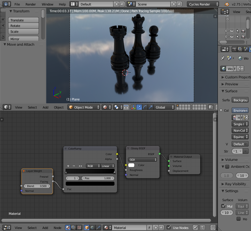
The left of the colour ramp has RGB value of 0.01, 0.01, 0.01 - the right hand side is 0.0, 0.0, 0.0.
You can tweak the roughness by changing the RGB values (keep them low though) - and can change the angle at which the transition takes place by tweaking the layer weight node value.
Yeah, sorry, that color ramp does exactly the same as what I explained as a lerp (at least in linear mode). I only prefer lerp (just a custom node group setup, nothing fancy) because it lets me see actual numbers I plug in rather than colors/brightnesses.
Also, what they call “micro roughness” isn’t something that is present in all material finishes in noticeable amounts. We don’t know Thea’s exact math, but the above is probably a workable approach. For sure less complicated than mine, but again, I prefer to work with visible numbers where numbers are expected rather than color nodes.
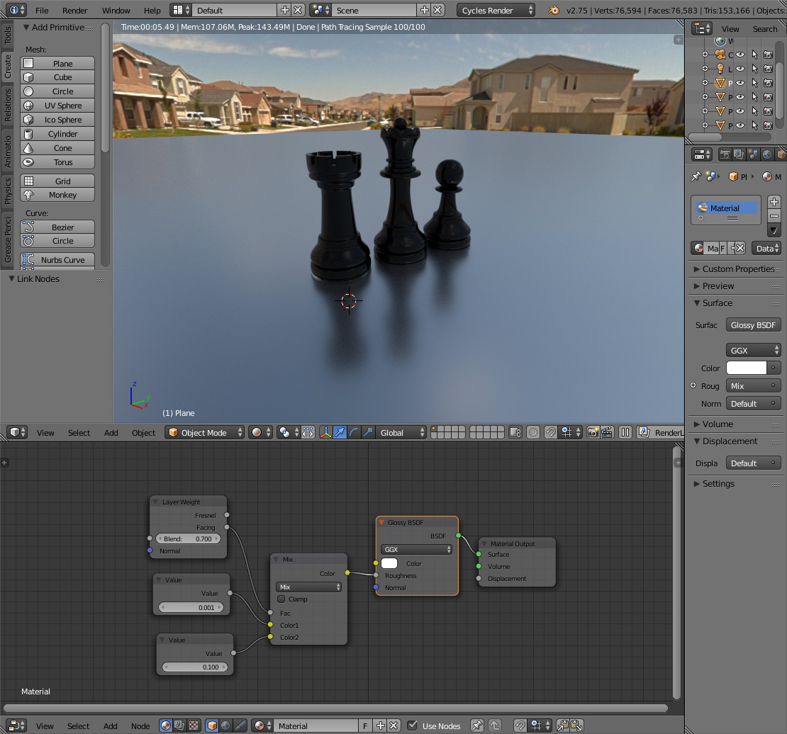
You can also string the output of the ‘facing’ parameter through a string of math nodes if you need more control over numbers (it has a number of modes like add, subtract, multiply, divide, power, logarithm, and others).
One thing you probably would want to do in these sorts of scenes is not use the displacement output… but rather a bump node -> the normal vector of the BSDF nodes & fresnel… This will also do away with the multiply math node as well as the bump node has a strength value.
Thanks all for your posts. Moony, I think your solution is great for tweaking the values! Also, what do you think is better, facing or fresnel curve for this case?
Doublebishop, which is faster, bump node or displacement? I took this way because I saw other tutorials with this way. I think that maybe they’re outdated.
I don’t know which is “better” - although “fresnel” many be more physically correct. At the end of the day it’s all down to personal preference - if it looks good and gives you the result you expect - use it.
I used “facing” because it was easy to get a good result quickly - but if I were looking to create a physically correct material, i’d probably look to use fresnel. The values may need tweaking though.