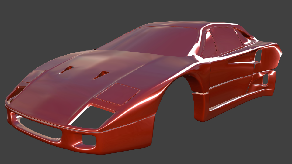
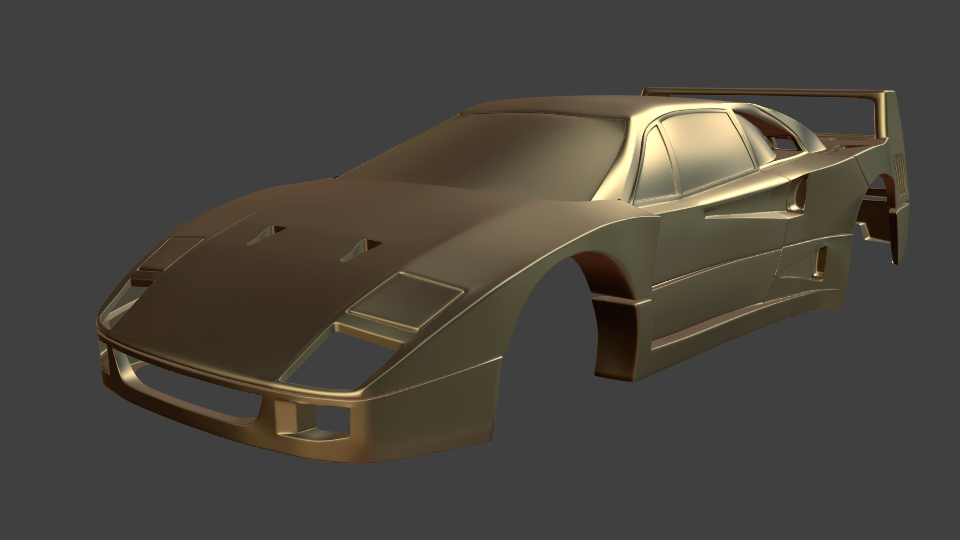
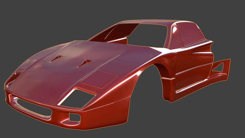
after i finished my cadillac which seems not to be top-notch enough yet (though i liked it), i decided to test my modeling skills again and i came up with another 80s car, this time a F40. Just started yesterday evening and will continue when i got some spare time. So this wont be a fast one i think, but it should have a good quality, which i try to focus on. Any feedback appreciated !
hell yeah, the model looking great so far , your modeling blows me out , i see how much i still have to learn.
Lets say procrastinating with Blender is not learning blender. I have a year using blender and i cant model like you…
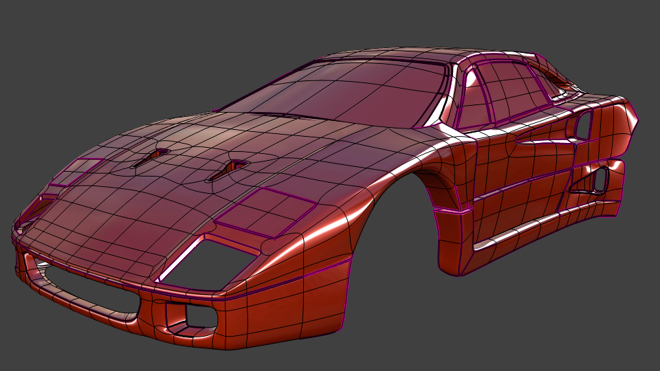
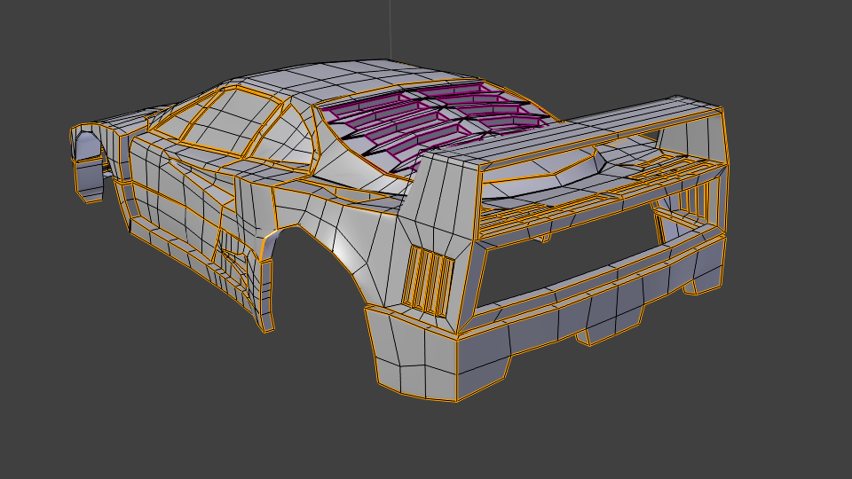
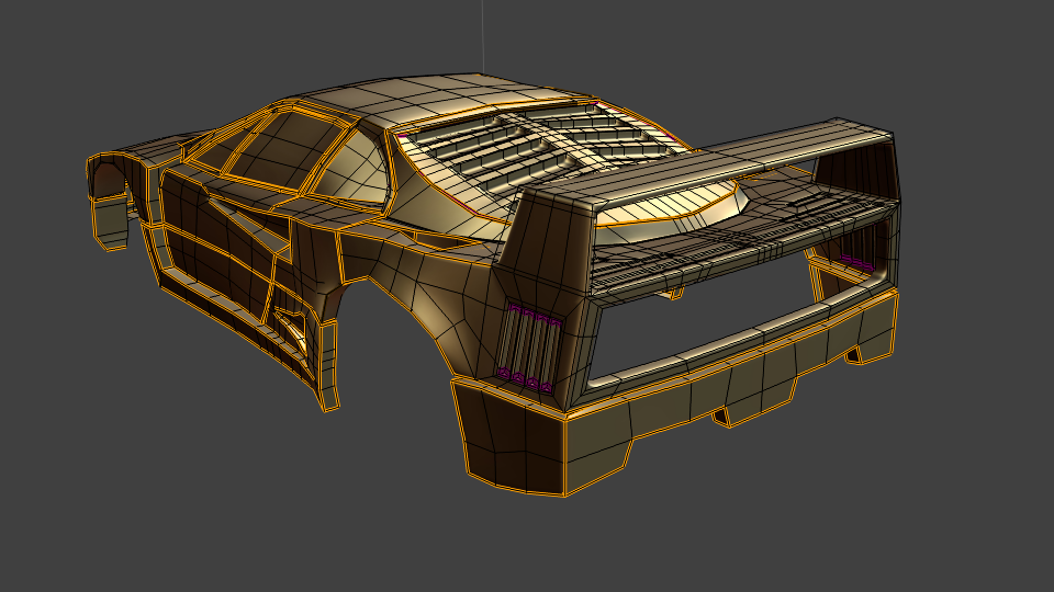
how do you acheived that quads , and what are the violet lines/edges ?
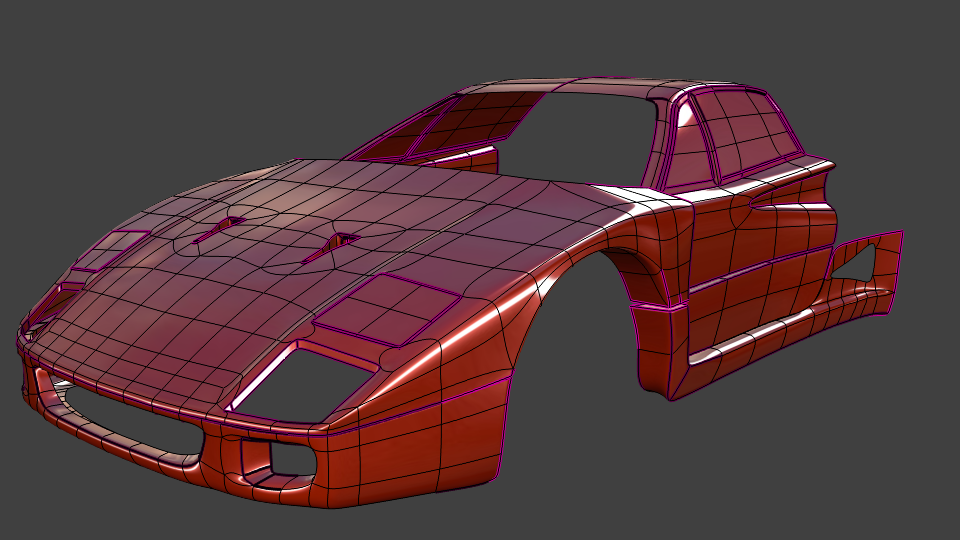
Those “bent” quads are displayed with subsurf modifier, edit cage on (all 4 “visibility” buttons enabled). For the hood, i basically blocked out the outline from top down view (blueprint, all verts in a plane). Then i made sure that on each side the subdivision count is equal so i can connect the edges to quads. That can be tricky… especially around the air intakes (?) i had to play around with the edge loops (hard to explain… its trial and error, atleast for me) so mostly quads can be built. i also have very few triangles too in smaller places, where its too hard to build all with quads.
I started with a 3x3 or 4x4 subdivision of the entire hood, add subsurf modifier from the beginning and leaving it on during editing, so the basic polycount stays low, the 2nd model has around 1000 faces only, but requires subsurf level 4 (level 3 might suffice too) and looks ugly as hell without subsurf. When i connected all quads still in the plane, i start to lift them edgeloop by edgeloop to build the 3d shape. (according to the side blueprint) I only add more subdivisions (mostly) when the basic shape is blocked out. That doesnt work always… so most of the time i also have to move around single edges or verts to clear the dents.
And last but not least, the violet lines are creases. Select edge and Shift E and then dragg the mouse or enter a value up to 1, this neutralizes the subsurf effect locally.
Sorry if this sounds all a bit confuse, but i am not so a good “tutor”.
Good progress already, scorpion! The F40 is one of my favorite Ferrari cars, so I’m very glad to see you taking on a subject such as this.
I recently saw a video showing use of “mean creases” to help in the preservation of hard edges. I hadn’t even heard of mean creases before, and on the off-chance that you haven’t either, maybe they will be useful to you.
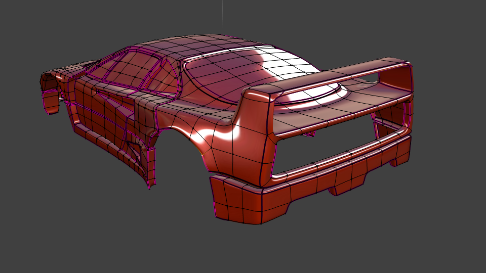
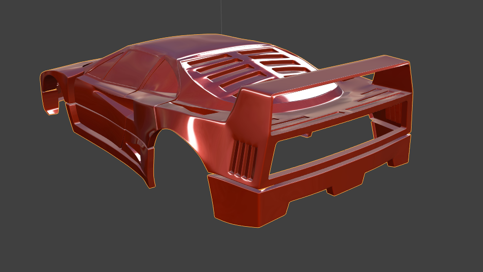
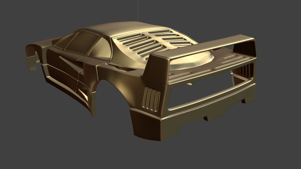
Some more progress, slowly approaching the back of the car
Lots of fiddly vertex movement, playing with creases and extrusions so far, lets see how that will be with the lights, wheels and maybe the interior…
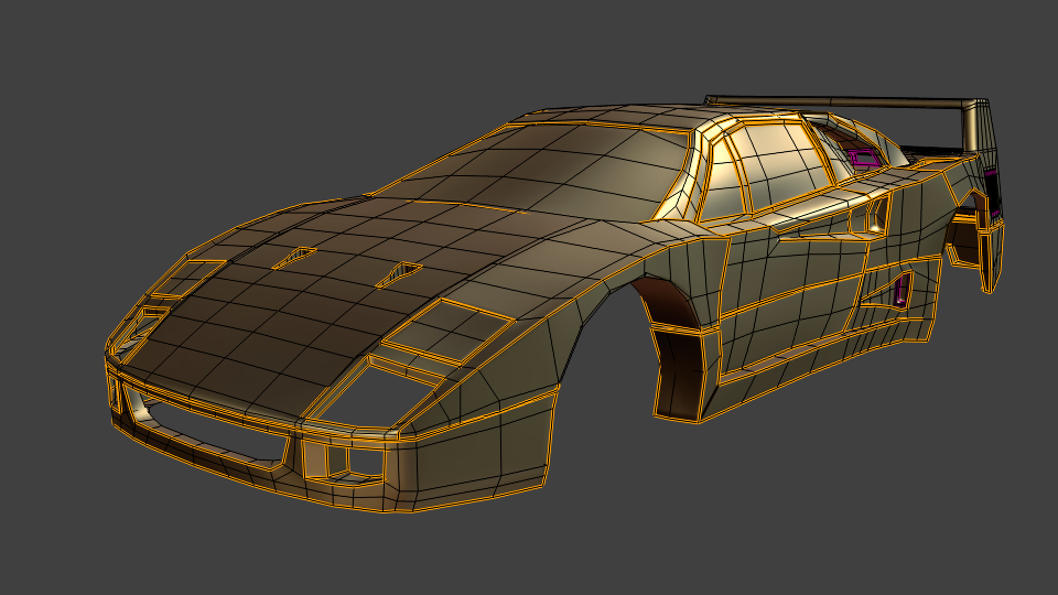
the topology is good, you should add more geometry (vertices) on the windshield.
also, the back part seem a bit “not that detailed” i don’t know if it’s on purpose.
yep, i only (relatively) quickly modeled the outline of the back, i will cut out details like air intakes / outlets later. Hmm. Maybe i should have made the holes first and have them surrounded by quads similarly its done on organic models (extruding “surrounding” edgeloops).
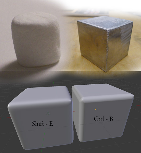
It looks a bit marshmallowy in places - I don’t think shift E is very good for making har edges - either extrude or loop cut manually, or use the bevel.
Might sound dumb, but is there a good way to “limit” the edgeloops locally (where you actually need them, otherwise they might run around the entire body and there can be mismatches in surrounding loop cuts… and i tend to get areas with dense loopcuts where they are not intended… Are ngons maybe an alternative too ? I atleast dont have good experiences with them… i try to use quads only if possible … and sometimes triangles are not avoidable too.
Another question: is it better to keep a very lowpoly basemesh (i have like around 1500 verts only maybe, but subsurf level 4) or make the basemesh more detailed and keep the subsurf lower, like 2 ?
Well, creasing works well for some extent, but in some areas i think i will swap them for extra loops … hmm, you said “marshmallowy”, does that mean too rounded still ? Or are there other disadvantages of creasing (shift - E) i am not aware of ?
A good way is to simply hide the face where you want the loop cut to stop.
I think, using the traditional poly by poly technique like you, use just enough polies to make the model accurate and the topology good (only quads and preferably not more than five edges connected to one vert). With too many polies you’ll end up with bumps and a mesh that’s hard to control. I think you have about right amount of poles, maybe the hood looks a bit dense, but as long as you can handle it it should be fine.
Well, if you can control your mesh, adding details on the base mesh is prefered, and a subsurf 2 to 3 max, because subsurface make the mesh more dense without the details that you want
not much progress here, mainly to messing around with crappy basemesh for hours, trying to cut correctly looking holes into it
I also swapped most creases for bevels now, except for the holes in the rear “window” above the engine. Hmm. Seems i cant get the right creasing without creating more unintended creases in the near environment. Tried to “inset” faces by extrude and scale inwards, but got 10-poles or so because the 5 poles touch each other at the mirror axis, very unsatisfied with those hole results so far.
Is there a better way to do this without exaggerating the base mesh with loop cuts and keeping the mesh controllable ? Have also many bumps there to fix still, they dont hit the eye that much with subsurf on, but without or bevel modifier before subsurf it does
i remade the front part around the holes, using ngons at this place now, trying to eliminate dents and shading errors around them, hmm did not work to 100%, but looks a bit better now than before. What do you think ? Did experiment some time to find the correct combination among crease, bevel, edgeloops and ngons, now i only need subsurf level 2, 80k faces total now.
… and the same drill for the back part. The bumps around the engine vents in the rear window were reduced a bit, for the cost of a pile of more edgeloops. Its not really easy to cut a perfect (complex shaped) hole into a bent surface, without getting shading errors around it (or atleast not too many)
Dunno whether it can be much better. Spent lots of time with it, fiddling around. And i dont think boolean modifier will do much better as well… maybe i should give it a try as well.


 Glad you like it !