

I know that via some addons I could do that but what about default Blender tools ?
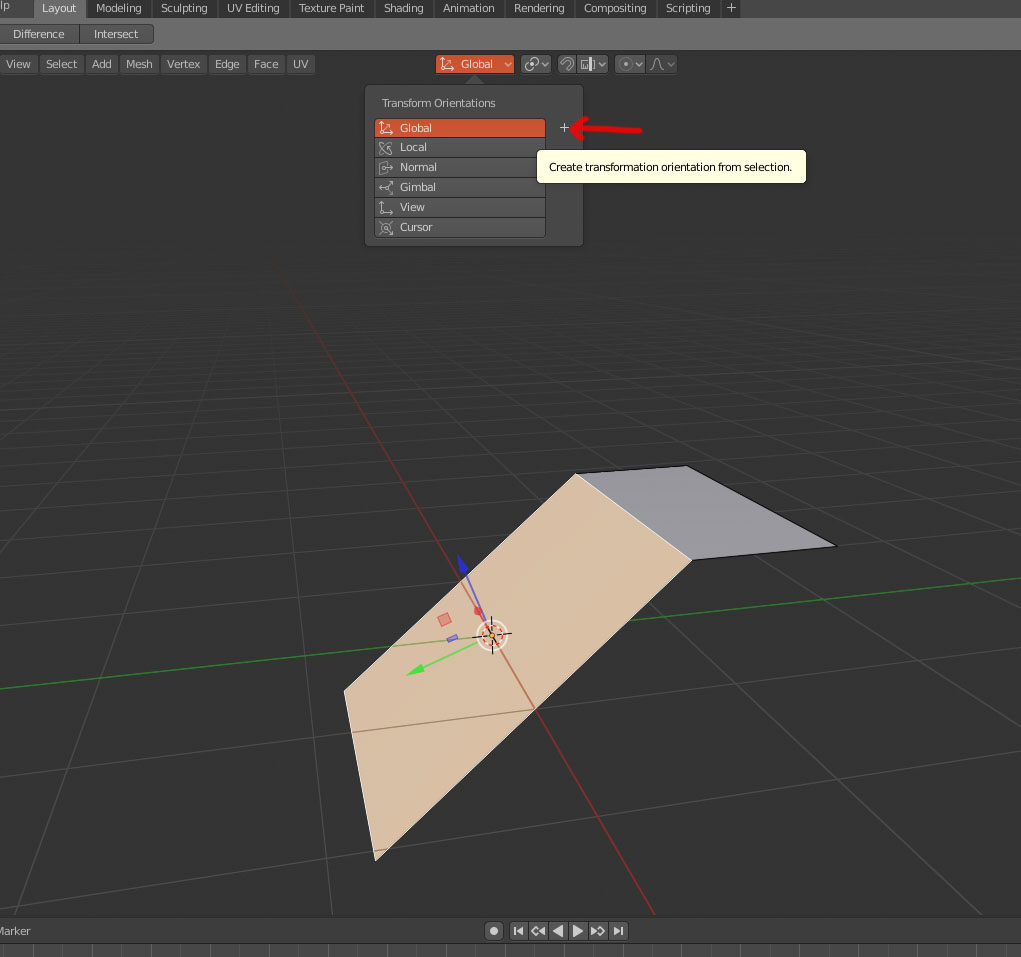
1- select the face you want to level to and hit the + button to create a custom transform orientation
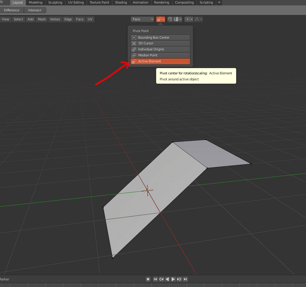
2- select “active element” as your pivot point
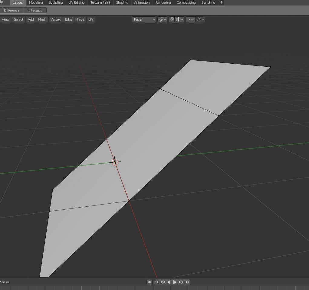
3- select your “wrong” points then the point you want to level to as your last selection

4- hit S then Z then type 0 to match the orientation.
2 Likes
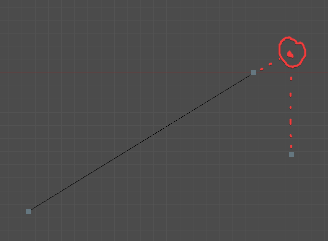
this way you get the vertex to align as projected along the Z custom axis, not vertically aligned with the original position.
As Sourvinos pointed out the vertices are aligned with the plane (good) but they are not aligned vertically with the original position. Try now to keep the custom orientation and align them to the global Z original position…
The issue is that snapping doesn’t work well when you are using constrained transform, otherwise it would be easy to do what you want in this case.
It’s a weak area in Blender currently, but hopefully something that can be addressed when looking at improved snapping in a forthcoming release.
6 Likes
If you are using view to align verts on an axis, I’ll use a camera with rotation locked on it as a placeholder for the view axis I need, just add a driver to the camera’s rotations and you should be good to go. (sloppy and hackish but meh, it works )
Another area which would be useful is snapping on things like edge/vertex slide. Lightwaves snapping left a huge amount to be desiered, but a plugin called LWCAD had some superb snapping, including “adjacent” and “projected” snapping, where you could snap based on relative positions of other things. It’s one of the few things I miss from LW, though granted it was from a £300 addon and not native.
Maybe it’s not super efficient, but in such scenarios I tend to rely on temporary geo helpers. Basically I’d model two plane guides and use the angle-constrained knife to mark the snapping target for the edge that you’d like to move.

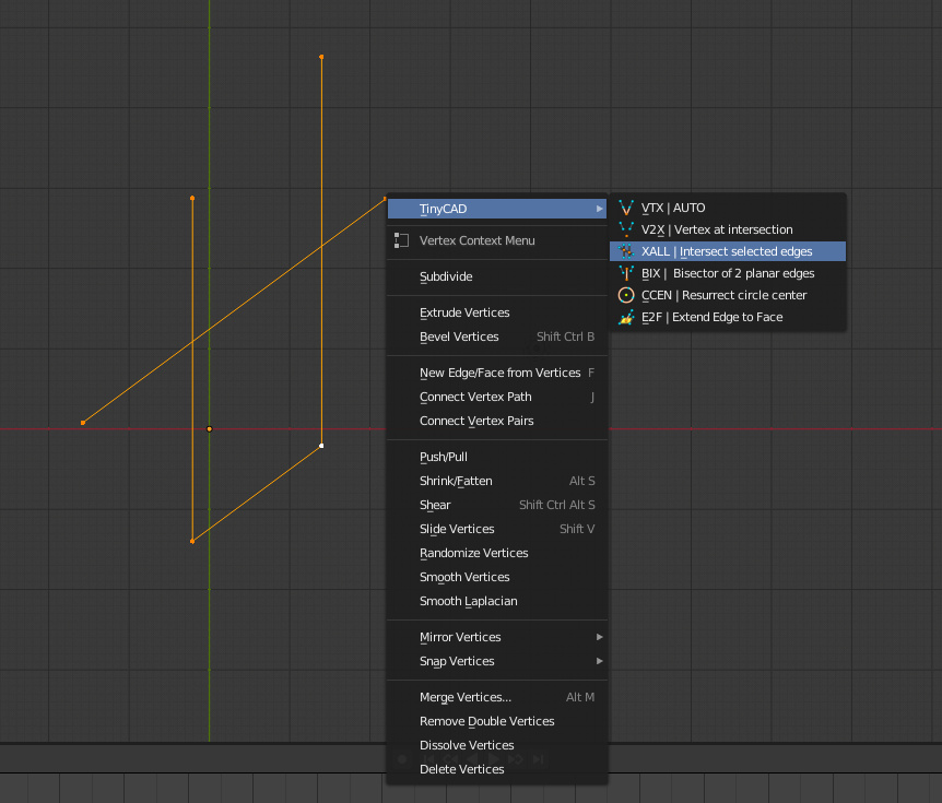
You could use tinyCad: extrude an edge directly upwards, then extrude/scale along your slanted edge, and then use XALL to intersect the edges
1 Like
This should be more intuitive and easier, without having to be relevant the transform orientation, without having to configure snap system or pivot.
Ctrl + E > Align selected to active Edge
Ctrl + F > Align selected to active Face
It is a wish, from a user friendly perspective. I have no idea if the above is exactly right, I am not even sure that the word “Align” is well used when referring to planes.
Edit:
For the third example,
Ctrl + V > Align active to (the other two) selected 
Yep, this is the “projected” style that LWCAD had, you can lock it to a relative point on an edge, or to a point on some other angle, it made the building of CAd stuff much easier.
Yep in this case we will need the snap happens also in the global axis
I hope too because sometimes I feel limited in the modeling process and spend time with workaround’s…
Yep slide with snap to global axis would be useful in these cases
Good sight I didn’t think about that it can be a good work around I will consider it next time
![]() That’s what I used to do it finally
That’s what I used to do it finally
Hope the devs or someone else that have the code science can fill this Blender lack ![]()
100% agree, I am hopeful given 2.80 has had some very nice nips and tucks.
I haven’t read the whole thread, I hope I’m not repeating here needlessly. Thought I’d throw in some of my insight as well.
-
Not that specific case maybe, but for many cases like that I find the OffsetEdges addon (works with 2.80) as my goto solution. It’s pretty reliable
-
SHIFT + V to slide vertices, while in slide press (and keep) ALT - now you can extend the slide beyond the edge limit.
-
I see you found TinyCAD
1 Like
This is a little gem I think people are oftne unaware of, it can be very handy!
I know about the ALT to lock the slide direction but in this case it lacks the snap to global axis.
You can obtain something close by using shear on Y and displaying Edge Angle value.
Blender had view aligning and projection from view before custom transform normal and snapping.
That is sufficient.
Select big inclined face.
Align view to its side Shift 1.
Change orientation to view.
Duplicate Face. Move it to cross Z axis that will be used for projection.
Scale it to be sure to snap vertices on it.
Change view to bottom Ctrl 7.
Select vertices to project.
Enable snapping. Faces as Snap Element. Active as Snap Target. Snap onto itself option enabled.
Then move vertices constrained along Z global axis.
(That would correponds to what a 2.4x project button would have done. Since it was removed to avoid redundancy with snap and shrinkwrap modifier.)
Delete the duplicate of face.
But that would be great to simply be able to place 3D cursor at a projected intersection of 2 edges or planes.
Hi @zeauro,
I’m trying your method but I think I surely miss something in the last step ? if I move the vertices along Z global to snap the face it’s not precise enough ?
1 Like
No, it is me. I made a mistake. Snap target does not matter.
You have to enable the last button (Project Individual Elements onto the surface of other objects).
This is too messy to be a solution, but it might be an interesting workaround
It’s possible to make some snap geometry with knife project, slide, separate and undo functionality.
If you separate a part of a mesh in edit mode it becomes a new object and undo history of the current object in edit mode does not apply to it any more. So you can construct some geometry for snapping, separate it and just undo all the mess you did to achieve it and since the separated geometry is in other objects current object’s undo will not affect it and you can still snap to it and delete it later:
I realize this is quite some workflow for such a simple thing, but it tends to work for me.