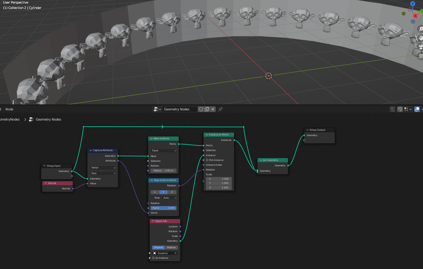
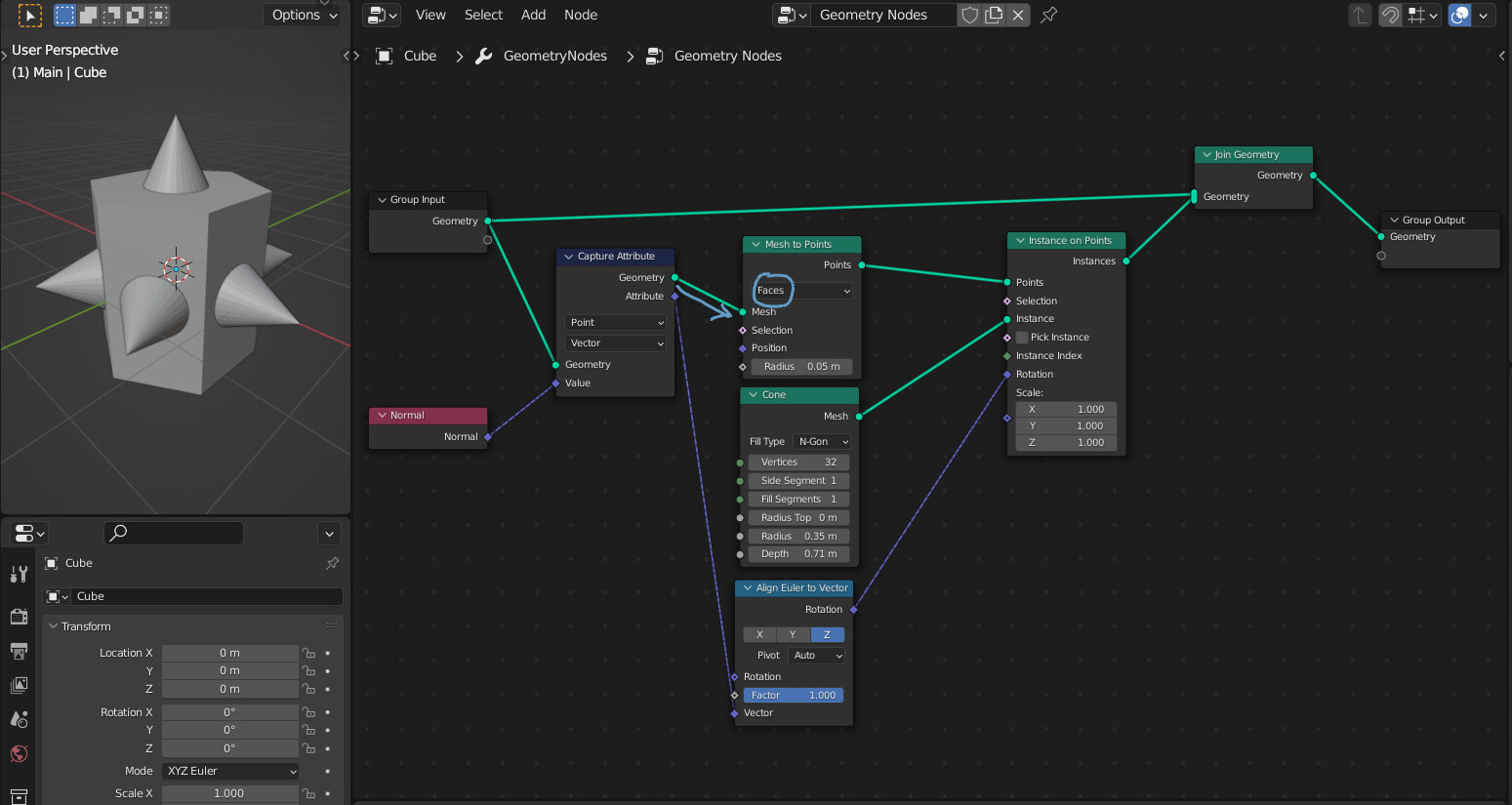
Capture the normal attribute on the original geometry, using face as the domain. Use the align euler to vector node to align the instance rotation to the captured attribute.
Also, to make the attribute capturing cleaner, I would recommend using the mesh to points node instead of dual mesh.
… so, it’s like saying “remember this for later”… and in this case by being in “Face” mode, its like saying “For each point, remember the face normal”.
This is extremely unintuitive. Intuitive would be “at this point in the process, capture the face normals, and then send them over to a point later in the process to be used. (like using a simple variable)”
That’s what the transfer attribute node is for. Transferring an attribute has no geometry output and allows you to evaluate the attribute later. Capturing is faster, and has better interpolation in the case that the geometry is modified.
I mean, that’s essentially what it does… still need to tell it where in the process the “data” needs to go, and you get that control by “following” a geometry chain. i.e. you can have many “data-flow” paths… so it can’t be avoided.
…and yes, good point about Attribute Transfer nodes by Zorro - those are used to “jump” geometry gaps to allow even more powerful “data-flow”, but requires a lot more processing.
Just for fun I tried Attribute Transfer node. After trying every possible combination of options in both that and the euler node I deduce that I am not smart.
I know it’s technically not flipping the normal based on what I remember reading but “normal” is the thing a lot of people will have in their heads as they’re searching for it.
Is there any way to keep uv map after realize instances?
Or is there any way to have the verts of instances snap to the nearest vert of nearby instances without actually merging… like a “snap by distance” node. Or is there a way to have a face that is being instanced on faces of varying sizes, snap each of its own verts to the corner verts of the parent face?
To work around not being able to do any of the above I would like to apply the Geometry Nodes modifier and manually weld the verts. But applying the modifier produces no geometry unless I add a Realize Instances node, which destroys the UV.
I am fairly sure that I read that this node actually just changes the winding order of the poly, so it switches from clockwise to anticlockwise or vice versa. As a result of changing the winding order, the normal is flipped.
Recap for context: Making a node-group to “disconnect” cyclic curves by creating a duplicate vert at the start-point (for multiple curves). This is 1st step in attempt to fix weird twists in curve-to-mesh when attempting things like mobius strips.
Progress on “Disconnect Cyclic Curve” support node-group:
Could not do this in 3.0… had to use extrude node from 3.1 to achieve above.
Issues in 3.0: Could not figure out how to index into separate curves. Anyone know how you can get vert-count per-curve (for multiple curves)?
Was thinking for 3.0 I could make a bunch of realized lines with vert count equal to vert-count of biggest curve then delete extra verts per-curve and re-map positions… was doable to just ignore all that and just use an extrude node in 3.1 but I’m stuck in 3.0.
Hi… I can attempt to answer this using the node-group I just posted above as example:
Its important to understand that the cyan noodles represent a “flow” of geometry data.
If you look at the bit labeled “End-Point Store” above, there I’m making new geometry by performing a delete on the original geometry. This “splits” the “flow” of geometry as you now have 2 different sets of geometry.
Capture Attribute only adds to the geometry “flow” it is on, so even though in the example you give the geometries are compatible, that is a special case… in general, the geometry “flow” can (and will) come from anywhere.
Without explicitly putting the Capture Attribute on that geometry “flow” the next node up the chain has no way of knowing how to “interpret” the incoming geometry.
In cases where there is a “split” in geometry “flow” you require a Transfer Attribute node (see the bit labeled “End Point OffSet Calc” above for example) to allow the next node up the chain to do things like distance checking, index-matching and whatnot to get the data across.
The point though is that Transfer Attribute is not a direct data mapping, it is inferred, whereas Capture Attribute is part of a geometry “flow” so therefore is a direct mapping.