HELP: first large scale low poly sculpture

Hello awesome blenderfam!

This is gonna be my first post in a forum I have been following for a while, I’m pretty stoked about this. This might not be the right place to post this but I hope I can at least find some direction from here. Your help is greatly appreciated.

So, just a little background:

I have been using blender for simple 3D rendering and modeling for quite some time now:
https://www.instagram.com/p/BezWWQ3hUEX/?utm_source=ig_web_copy_link

, honestly it’s the best program out there IMO. And it’s because of you guys! The community aspect of it beats all other competitors. Earlier this year, I started collaborating with a friend of mine who needed renders made for his sculptures. He’s made things for burning man, Chicago parks district, etc.


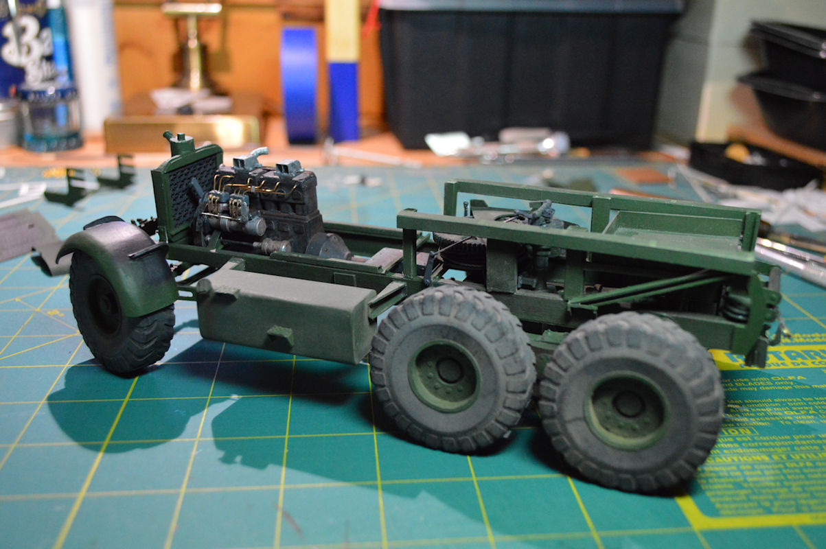
We started working on some renders for proposals and after sometime I found myself at his studio constantly, now helping him design the fabrication and engineering aspect of his sculptures (I will attach some pics for reference). I have been mainly using blender to sculpt polygon based topographies, and haphazardly understand them in terms of geometry and fabrication. So far it’s been good as it fits his aesthetic. But now I have reached a MAJOR roadblock: going from design/render to actual sculputure.

I have had good luck figuring this out by myself, but I really need your help now, with any ideas that you may have of where to go, who to ask, and what are the right questions to ask, or programs that I could fit into my workflow, tips, a thing helps.

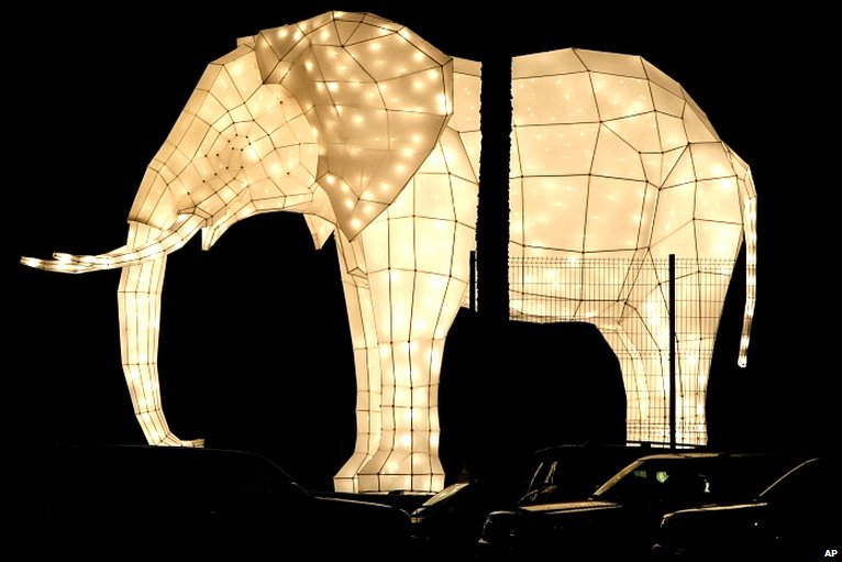
This is what we’re trying to make a reality:

What you see here are three concentric rings where each one has a higher level of complexity than the one before, the first object having 75 tri’s, the second 150, and the third 357. Were using dichroic acrylic as it’s the material of choice for my friends work. He’s had a lot of experience with building low poly structures (but never ones that are as irregular as this). The planes are attached to each other by brackets, or a frame, or (suggestions?) and then are hung with aircraft cable to the ceiling.


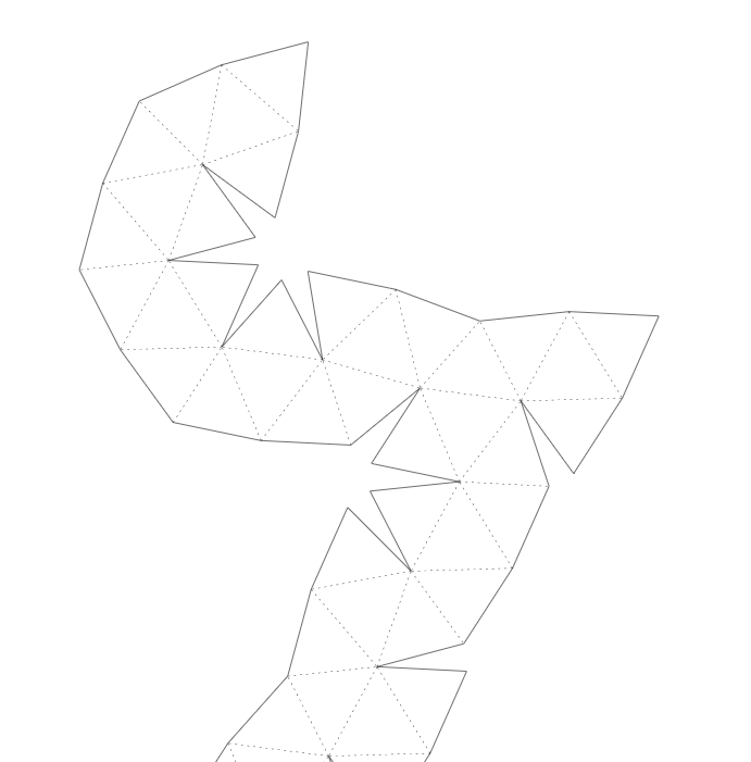
I started by thinking about how to unpack the mesh into a pattern that could be laser cut out of acrylic. That process was pretty straightforward, as this is pretty standard for low poly paper modeling, which I have no experience with but has been my northern star for all of this. Blender had some options, but pepakura really gave me what I have needed (so far). for those of you that dont know it, its a great piece of software that turns 3d objects into foldable paper models.

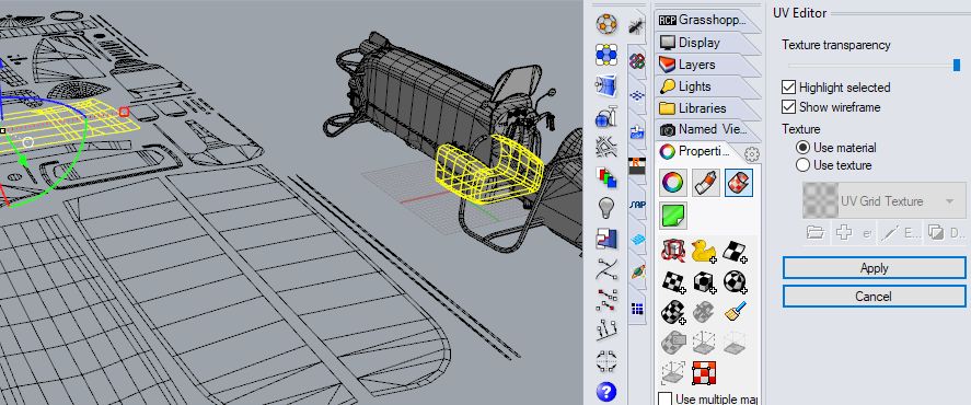
I took the topmost piece in the sculpture and brought it into pepakura to make this cardboard model:

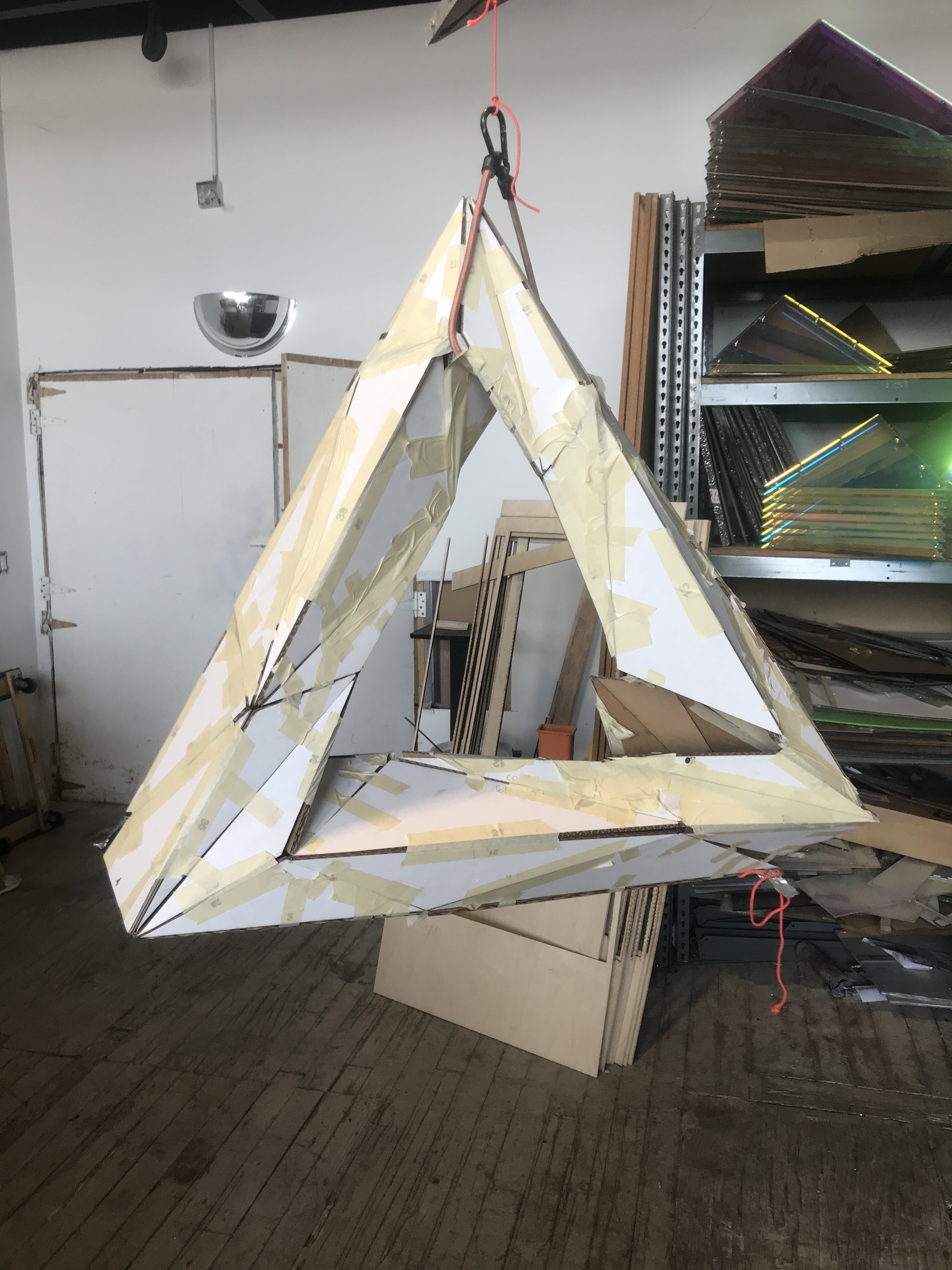
This was somewhat of a complicated process as there are material dimensions that need to be taken into consideration when two faces meet at a certain angle (particularly really Acute ones), but this was a pretty good way to understand the shape in space. The hardest part was going from an unfolded shape to a folded one, as it was really confusing and hard to keep all of the faces together with the tape. We thought a frame would help best in attaching the faces, and it gives us flexibility if we were to Tessa late or break faces. But I’m resching a real mental block when thinking about how we would get to building a frame, how to manufacture that, how to figure out all of the angles between faces, automating that process etc. Seems like blender might not be the right choice, but I must be missing something. I will update and edit this thread as the project develops but welcome to my personal little heaven and hell! Hope you enjoy it and thank you for your contributions.

I assume that by “frame” you mean making a representative cage that you use as the basis for the gluing process. If so making a custom skeleton frame of your initial models is not that hard, you can enable vertex snapping and start drawing edges (e to extrude a vertex) in a new mesh. You could try various frame shapes, once you feel like you hit the spot, you can maybe get it printed.

To get an idea, just take your model and apply “wireframe” modifier. That can be printed as well, if you have access to a 3d printing house. However tracing your initial model (like I explained above) with edges will give you an optimum shape.

1 Like

I’m gonna try to explain here a process tu build huge polygon structure based on 3d file.
An example i’ve done (not alone of course)

Sorry! There is a palm tree just in front the elephant. Trying to hide it.

-for that we need:

  • a wooden plank really flat droped on a flat floor ( matching the size of your model)

  • Laser CAD Pro ( to point precisely vertices from top view) (you can rent it)

  • A truskin (big one) Marking Gauge to place precisely the z position

  • Some meters of metallic tubes determined by the numbers of edges you v’ got in your models and there length. (the thickness is determined by the solidity you need) can be empty inside or plain.

  • Some Metal Balls determined by the number of vertices you’ve got in your meshes. They can be also plain or empty inside (depending of the size you need for welding on it. Example
    Up to you to find the best prices for your needs.

  • a welding machine (better use a good one)

  • Blender / a vertex utility addon to reorder the index after modeling / a good dxf exporter or SVG

  • a spreadsheet software libreoffice or any hegemonic f****ing software you have with shame on you.

  • A big place sized for hanging the laser on a sufficient distance. and with a door sized to get out the stuffs.

  • A brain

I could be more precise on the walk through, but for the moment, let see if it’s what you need.

Dont forget to subscribe to my non existing channel to make the earth water level raising up.

1 Like

@looneystein . No more interest in that?

1 Like

A CAD application will help when it comes to figuring out angles between faces and/or creating miters. Working with the material thickness, booleans, and trimming surfaces will improved in a CAD application.

Some CAD apps can work with meshes to an extent, so it may be possible to use work you have already done in Blender.

You could get trials of Rhino and Moi3d.
Moi3d does not have built in mesh import but does have some scripts to allow importing of meshes as wireframes. It’s not as convenient as having the mesh options that Rhino has, but its also less costly and the interface is much simpler. It also does not produce 2D dimensioned drawings. But you could get a low cost or free app for that.

EDIT: Fusion360 might be another CAD application to consider.

1 Like

wow this has to be the best damn post ive seen on this subject. tha elephant looks amazing, good idea of using metal tubes as edges and balls as vertices is great, specially for a permanent installation.

the use of this laser seems more complex, but might give us exact layouts of what we need to build.

these F***G softwares man! shame

i am excited to talk more about this and exchange some ideas. thank you skuax

Thanks for replying chrisd!

i have been looking to move onto fusion360, but am trying to stay within blender so i dont have to dedicate the learning curve time to another software. although the more i move into this type of design it seems luike a blender-fusion workflow makes sense.

do you know of anywhere in the blender community that i could look at in order to progress further with the use of blender?
thank you

can you explain how this would be different from just using the wireframe of our current model? maybe im missing something here

There are a few add ons for measuring that might be useful.

Meshes are less than desirable for CNC work.

The shapes are triangular and flat and that will help things somewhat. However, if you need to put holes or notches in, the opening will break the face into multiple triangles, you may have to do a lot of cleanup to get rid of the edges in the interior of the face to use for CNC.

Someone might have a way to get rid of all the interior edges quickly.

I’m not sure if this will help, but it is possible to show all of the polygon angles from a Python script. Here’s one I just wrote:

import bpy
import math
import mathutils
import os
os.system("cls")    # Clear the console output

# Loop over all objects and print out the angles of all the faces
scn = bpy.context.scene
for obj in bpy.context.selected_objects:
    print("Faces in "+obj.name+":")
    mesh = obj.data
    i = 0
    for poly in mesh.polygons:

        numVertices = len(poly.vertices)

        # Print center position
        centerPos = mathutils.Vector([0, 0, 0])
        for v in poly.vertices:
            centerPos += mesh.vertices[v].co
        centerPos /= numVertices
        print("Face "+str(i)+" at "+str(centerPos)+": ")
        
        # Print lengths
        print("  Lengths: ")
        for polyIndex in range(0, numVertices):
            vertIndex0 = poly.vertices[polyIndex]
            vertIndex1 = poly.vertices[(polyIndex+1)%numVertices]
            vertex0 = mesh.vertices[vertIndex0]
            vertex1 = mesh.vertices[vertIndex1]
            edge = vertex1.co - vertex0.co
            length = math.sqrt(edge.dot(edge))
            print("    "+str(length))

        # Print corner angles
        print("  Corner Angles: ")
        numVertices = len(poly.vertices)
        for polyIndex in range(0, numVertices):
            vertIndex0 = poly.vertices[polyIndex]
            vertIndex1 = poly.vertices[(polyIndex+1)%numVertices]
            vertIndex2 = poly.vertices[(polyIndex+2)%numVertices]
            vertex0 = mesh.vertices[vertIndex0]
            vertex1 = mesh.vertices[vertIndex1]
            vertex2 = mesh.vertices[vertIndex2]
            edge1 = vertex0.co - vertex1.co
            edge2 = vertex2.co - vertex1.co
            length1 = math.sqrt(edge1.dot(edge1))
            length2 = math.sqrt(edge2.dot(edge2))
            radians = math.acos(edge1.dot(edge2) / (length1 * length2))
            print("    "+str(math.degrees(radians)))

        # Print edge angles
        # (0 means the planes are parallel)
        print("  Edge Angles: ")
        numVertices = len(poly.vertices)
        for polyIndex in range(0, numVertices):
            vertIndex0 = poly.vertices[polyIndex]
            vertIndex1 = poly.vertices[(polyIndex+1)%numVertices]
            
            # Search through all other polygons to find one that shares this edge.
            for otherPoly in mesh.polygons:
                if (poly != otherPoly):
                    numOtherVertices = len(otherPoly.vertices)
                    for otherPolyIndex in range(0, numOtherVertices):
                        otherVertIndex0 = otherPoly.vertices[otherPolyIndex]
                        otherVertIndex1 = otherPoly.vertices[(otherPolyIndex+1)%numVertices]
                        if ((vertIndex0 == otherVertIndex1) and
                            (vertIndex1 == otherVertIndex0)):
                            thisNormal = poly.normal
                            otherNormal = otherPoly.normal
                            radians = math.acos(thisNormal.dot(otherNormal))
                            print("    "+str(math.degrees(radians)))

        i += 1

Run Blender from the command line, open this in the text editor and press the “Run Script” button. It will print out all of the polygon and edge angles to the command line.

This might be just an overload of information since it just prints the values without generating an image, but it might be some help.

1 Like

Well I was more thinking in terms of simplification, naturally if your model is very simple you can use wf but for more complex models you can go with what I mentioned. See the image (manually traced the suzanne model)

1 Like

Since you don’t need textures and only need the faces from the object…as individual objects. You could use the Blender card_model Plugin that is included in Blender just need to activate it. It will export the flattened mesh to PDF or I use .SVG … once in .svg can be imported to Inkscape and scaled then saved to a Robo cutter .dxf file… then sent to whatever you use to cut… I sent mine to a CNC water jet cutter and had the parts done in 1/8th stainless, then welded.

Just did a quick Ico-Sphere and exported as .svg. I did not add seams which would break into parts or control the flattening…but this should give you an idea…the program actually works better and has more options in 2,79b…


It will actually work far better then Pepakura in most cases.

1 Like

hey Komojo!
thanks for the reply, yes this would be very useful but without being able to identify what angle/length goes where it would be extremely hard to match them if were dealing with 150+ angles and lengths. this is very helpful tho, because i would like to be able to write scripts like these myself. where did you learn pythn? can you point me to any resources?

thank you so much,
-Adrian Stein

YES!!! this is the process we are using but using pepakura as our middleman between blendr and real life, so far it has proven to be really good for slicing the model and putting it back together. do you have any pictures or video of the model you made??

No video but …


All card stock plus some wire and some brass sheet.

1 Like

I was thinking more about this and you might find better luck with all the requirements you need by using Rhino. It is far more capable in this realm for flattening and getting detailed print-outs of parts, as well as packing the flattened pieces onto a specific sized sheet ( making all the parts fit as best as possible, on sheet ad at real-world scale, using Grasshopper plugins).

Do you have a Fab-lab, somewhere near you? Fab-Lab Home
They are the best source of getting 3d to fabrication anywhere and are Non-profit.

1 Like

I updated my Python script to show the labels in 3D. Maybe this could be useful.

#
# Blender model lengths & angles
# Python script by Komojo
#

import bpy
import math
import mathutils

#
# addMarker: Add an empty object with a label at a specific location
#
def addMarker(position, name, collection, parentObj):
    # Create a new empty object with this name
    obj = bpy.data.objects.new( name, None )
    obj.empty_display_size = .01
    obj.empty_display_type = 'PLAIN_AXES'
    obj.show_name = True
    
    # Transform the position
    obj.location = parentObj.matrix_world @ position
    
    # Add to the collection
    collection.objects.link(obj)


#
# getOrCreateCollection: Create a collection if it doesn't exist
#
def getOrCreateCollection(name, parentCollection):
    if (bpy.data.collections.get(name)):
        collection = bpy.data.collections[name]
    else:
        collection = bpy.data.collections.new(name)

    if (parentCollection.children.get(name) == None):
        parentCollection.children.link(collection)
    return collection

#
# deleteObjects: Delete all objects in a collection
#
def deleteObjects(collection):
    for obj in collection.objects:
        bpy.data.objects.remove(obj, do_unlink=True)
    for child in collection.children:
        deleteObjects(child)
        bpy.data.collections.remove(child, do_unlink=True)
    
#
# processObject: Add markers for the lengths and angles of each model
#
def processObject(obj):

    # Create a collection for this object
    collectionName = "Labels_"+obj.name
    labelCol = getOrCreateCollection(collectionName, bpy.context.scene.collection)
    deleteObjects(labelCol)

    mesh = obj.data

    # Create a collection to see which face is which
    faceCol = getOrCreateCollection(obj.name+"_Face_Labels", labelCol)

    # Show  faces
    i = 0
    for poly in mesh.polygons:

        # Create a new collection for this polygon
        collectionName = obj.name+"_Face_"+str(i)
        polyCol = getOrCreateCollection(collectionName, labelCol)
        #polyCol.hide_viewport = True       # This doesn't seem to be working?
        
        # Delete any empty objects that might exist from a previous time
        deleteObjects(polyCol)
            
        numVertices = len(poly.vertices)

        # Find center position
        centerPos = mathutils.Vector([0, 0, 0])
        for v in poly.vertices:
            centerPos += mesh.vertices[v].co
        centerPos /= numVertices
        addMarker(centerPos, str(i), faceCol, obj)

        # Scale the labels inwards slightly so they don't overlap
        SCALE_AMOUNT = 0.98

        # Show corner angles
        for polyIndex in range(0, numVertices):
            i0 = poly.vertices[polyIndex]
            i1 = poly.vertices[(polyIndex+1)%numVertices]
            i2 = poly.vertices[(polyIndex+2)%numVertices]
            vertex0 = mesh.vertices[i0].co
            vertex1 = mesh.vertices[i1].co
            vertex2 = mesh.vertices[i2].co
            edge1 = vertex0 - vertex1
            edge2 = vertex2 - vertex1
            length1 = math.sqrt(edge1.dot(edge1))
            length2 = math.sqrt(edge2.dot(edge2))
            radians = math.acos(edge1.dot(edge2) / (length1 * length2))
            angle = math.degrees(radians)
            #  ".3f" = 3 decimal places
            #  "(polyIndex+1)%numVertices" = shifted index for easier modulo math with %numVertices
            #  "{0}_{1}" = objects must have unique names
            cornerName = "Corner{0}_{1}:  {2:.3f}".format(i, (polyIndex+1)%numVertices, angle)
            
            # Shift the position inwards and add a marker
            centerToVertex1 = vertex1 - centerPos
            cornerPos = centerPos + (centerToVertex1 * SCALE_AMOUNT)
            addMarker(cornerPos, cornerName, polyCol, obj)

            # Try to find two polygons that share this edge
            for polyB in mesh.polygons:
                if (poly != polyB): # Don't check this polygon against itself
                    numVerticesB = len(polyB.vertices)
                    for polyIndexB in range(0, numVerticesB):
                        vertIndex0 = polyB.vertices[polyIndexB]
                        vertIndex1 = polyB.vertices[(polyIndexB+1)%numVerticesB]
                        if ((vertIndex0 == i0) and (vertIndex1 == i1) or
                            (vertIndex0 == i1) and (vertIndex1 == i0)):
                            # Found two polygons sharing this edge
                            # Compute the angle between the edges from the normals
                            cosine = poly.normal.dot(polyB.normal)
                            radians = math.acos(cosine)
                            edgeAngle = math.degrees(radians)

                            # Shift the position inwards and add a marker
                            edgeCenter = (vertex0 + vertex1) * 0.5
                            centerToEdge = edgeCenter - centerPos
                            edgePos = centerPos + (centerToEdge * SCALE_AMOUNT)
                            edgeName = "Edge{0}_{1}:  Angle {2:.3f}   Length {3:.3f}".format(i, polyIndex, edgeAngle, length1)
                            addMarker(edgePos, edgeName, polyCol, obj)
                            
        i += 1

#
# Main Function
#

# Loop over selected objects and print out the angles of all the faces
for obj in bpy.context.selected_objects:
    processObject(obj)

If you run this version with the object selected, it will create a bunch of Empty objects with text labels and put them in separate collections for each face. There’s also a collection that shows the face indices so you know which is which.

If you don’t know, you can also increase the font size in the user settings and enable syntax highlighting in the text editor.

3 Likes

deffinately something im looking into, but at this point in the project it would be too time consuming to learn another software entirely. im deffinately considering it tho

Yeah! I hear that…I was thinking more along the lines of someone that uses Rhino already and could produce the necessary files for you as the objects are about as simple as can be, and using Rhino with Grasshopper the script by @Komojo would be a click away…as well as a flattened pattern with all the details ready to go to CNC, and that is also why I asked if there is a FABLAB near, they have ALL the tools to do the job…