[Help] Modeling medieval tower

Hey, fellow blenderheads :slight_smile:

The local castle has been lying in ruins for several centuries so I’ve assigned myself with the task to remake it virtually.

What seemed to be simple enough (“hey, it’s all generic shapes like cubes and cylinders”) turned out to be problemativ when it comes to details.

The towers are cylindrical in shape and have several openings like so:
http://img230.imageshack.us/img230/5048/69606rh8.jpg

Now I tried my luck with boole’ans. :no: No use, for that turned the “mesh” in a “mess”. Like so:
http://img86.imageshack.us/img86/1450/geboolterturmbn3.jpg

Then I tried extruding and scaling several faces. That deformed the mesh as well.
Like so:
http://img75.imageshack.us/img75/554/extrudierterturmpk6.jpg

I dare not think about unwrapping…

I’d like to have a clean mesh with all of the necessary openings (there is a door there somewhere, too!) that I can unwrap reasonably easy.

So I sincerly hope someone of you can tell me how to properly do this or at least give me some pointers.
Thanks in advance :slight_smile:

Hey there, nice subject matter.Beats the 20th century rubble 'round here. :evilgrin:

I’ve got a way that should work for you. What I did create a 32 sided circle then extruded it to give height to the castle. Then I hit ctrl-r and divided the thing into 7 sections height wise.
From there, I just removed faces where I wanted windows, then extruded the whole thing. Switching to top view, I scaled by 0.9 in X then 0.9 in Y, this way we form all surfaces of all windows at once and avoid it getting shorter when we scale it in.
You’ll need to subdivide it a bit or add some extra loops in around the windows to avoid nasty smothing.
Here’s what I came up with.
Simon.

Attachments


Another approach is to start with the details. Build a generic window out of the window profile, using extrude and rotate (about the center of the tower). Remove the interior edges on the outside of the window and spin dup the window around the circumference of the tower.

Next, use the same profile for the wall profile (your tower has courses with windows, and courses with no windows), duplicate the profile, lower it and spin it. Remove doubles.


That will give you a basic wall without windows, and generic windows placed about the circumference of the wall. Select windows and rotate them about the center of the tower so they line up inside a wall section. Duplicate the wall and window sections, and assemble them into the tower by deleting the wall edges where a window will be, and moving the window into the opening. Make faces between the wall sections and the windows (Face loops come in handy to save time.)

Once you have assembled the wall section with the windows, you can adjust the individual windows to match the reference.

Haha :slight_smile: Well, I might just put a flakcannon on one of those towers for added flavor :wink: :smiley:

That’s a nice one! Very intuitive and I shall try it at once! Thanks very much, Simon!

Just by reading I didn’t get your technique yet :o But I will do the steps you described in Blender and I am sure it will become clear to me then. At least your example looks quite right :slight_smile:
Thank you, too!

Woa, once again this forum has proven to be very helpful! Thanks to you guys!

Do you have references for what the tower used to look like? Photos, drawings, etc?

Some things to add to the above good advice:
-Edge Split modifier helps a lot to get a smooth result without destroying the edges around windows. (You don’t need to use subsurf, just set smooth, if you need to save on memory)
-Keep in mind that the reason we like quads (and hate the messy mesh created by booleans) is that the edge-loop creation process (CTRL-R) doesn’t work over triangles. That said, you can still do booleans (there’s a modifier now) and clean up the mesh after the fact for really complex intersections, if the area is limited.
-When doing an edge-loop for openings, you want to get both inside and outside loops in the same place. I like to just create them both in the center of the mesh and then select both in a front view, then move them where I want them at the same time
-The Array modifier is your friend. Read up in the manual on how to use it in conjunction with empties to get rotational copies
-When working with a cylinder, you always seem to get openings off the polygonal vertex that makes the plan view. When you do, you want to avoid subdividing the plan-view polygon edges and use copy or extude + rotation about the center of the tower. This goes for doing a vertical edge-loop up the side of the tower as well.
-Create a few empties at various center points in the tower (top, midpoint, etc) since true center points can get lost when you delete vertices around the walls.
Lucky you - you have the wall texure already!:eyebrowlift: Hope I was of some help.

Yes, I do. There are still two towers standing so I can go and study them in real life. And I have copies of several drawings which were made in 1641. They were made before the castle was first shot into bits, then stormed and raized. Except for mentioned towers.

Thanks for your advice which I will keep in mind (and scribbled into my Blender reference note book :wink: )
I just failed to understand this:

-When working with a cylinder, you always seem to get openings off the polygonal vertex that makes the plan view. When you do, you want to avoid subdividing the plan-view polygon edges and use copy or extude + rotation about the center of the tower. This goes for doing a vertical edge-loop up the side of the tower as well.
Which “polygonal vertex that makes the plan view”? :eek:

Lucky you - you have the wall texure already!:eyebrowlift:
Only half lucky :wink: for I still have to take photos, make them tileable/ adjust them so I can put the UVs on them and so on. That’s gonna be a pain in the you-know-what.

You’re right, pictures are better.


Create a window profile in side view. Add a plane, extrude the top edge up, extrude the bottom edge down twice. Use z to constrain the extrude to the z axis so it doesn’t get wobbly.


I left the 3d cursor at x=0 y=0 z=0 and moved the window profile in the y direction 10 units. [a, g, y, 10].

If your 3d cursor has a bad habit of wandering because of random LMB clicks, you can snap it to the grid in the center using Shift+s>>Cursor to Grid. You could also place another object at the center (like a cube), select it and snap the cursor to the selection (which is usually easier, since you don’t have to pre-position the cursor near the grid to get it to snap to the correct grid intersection.)

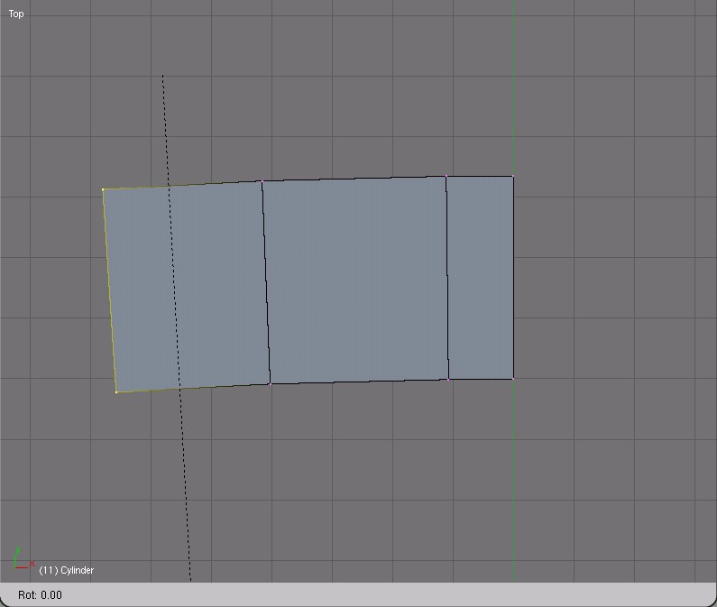
With the window profile 10 units from the 3d cursor, and the pivot point changed to the 3d cursor [type . (that’s a period)] you can extrude and rotate into place the rest of the window. [type e, esc, r then move the mouse or type in some number of degrees.] Do your rotations in top view. Although it probably won’t be noticable, the rotation makes the window follow the curve of the wall.


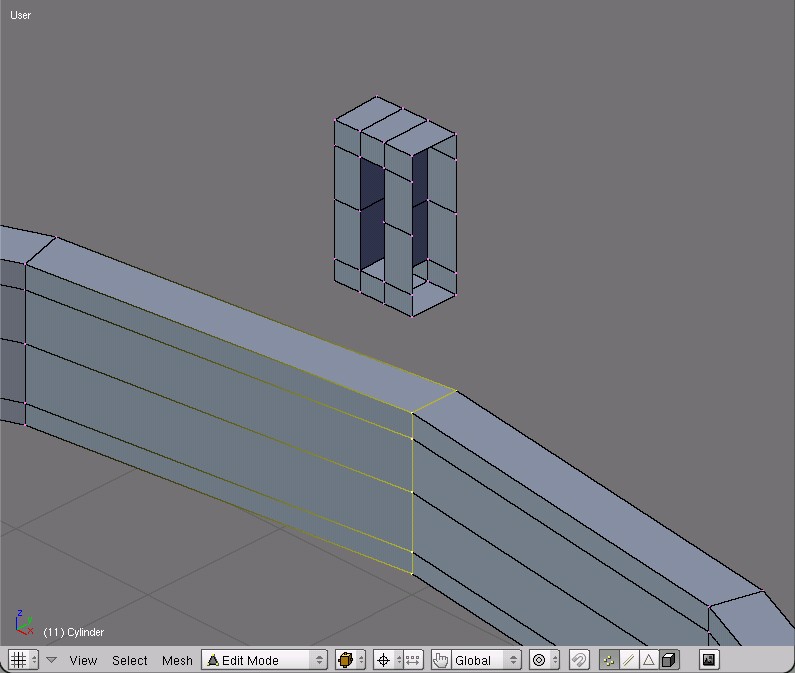
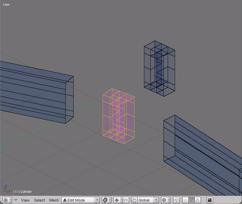
To make a window out of the rectangular mesh produced by the previous step, you’ll need to delete the faces in the window opening (on both sides of the wall) and fill in the faces between the wall. The simplest way to do this is to select both inside edges (with alt+RMB then Shift+alt+RMB with the cursor first on one edge, then on the other) and use F>>edge loops to make the new faces.

The above image shows this already done.

Then select the three edges on the outside and delete them (both sides), so you won’t get any interior edges or faces when you connect the window to the wall section later on.


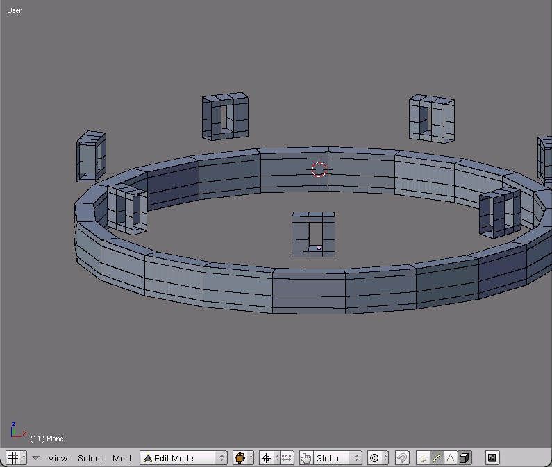
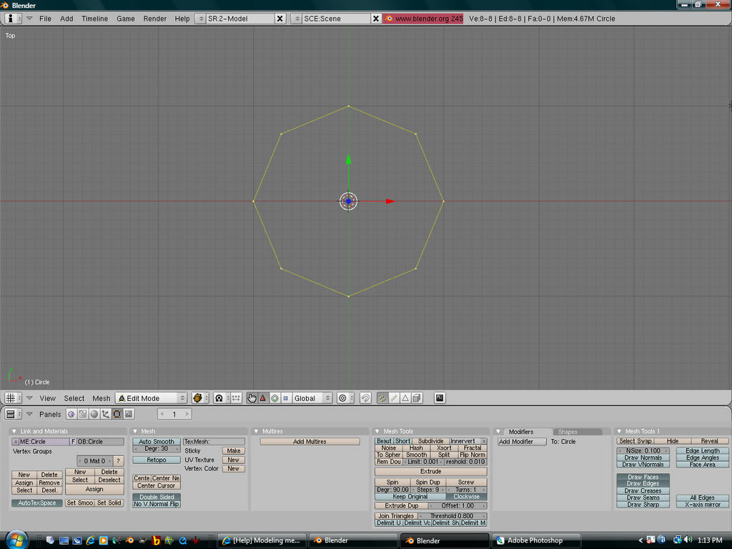
Select one of the outside edges (alt+LMB) duplicate it (Shift+d) and move it down (g, z).


In top view, spin this profile around the 3d cursor, use 360 degrees and at least 20 steps.


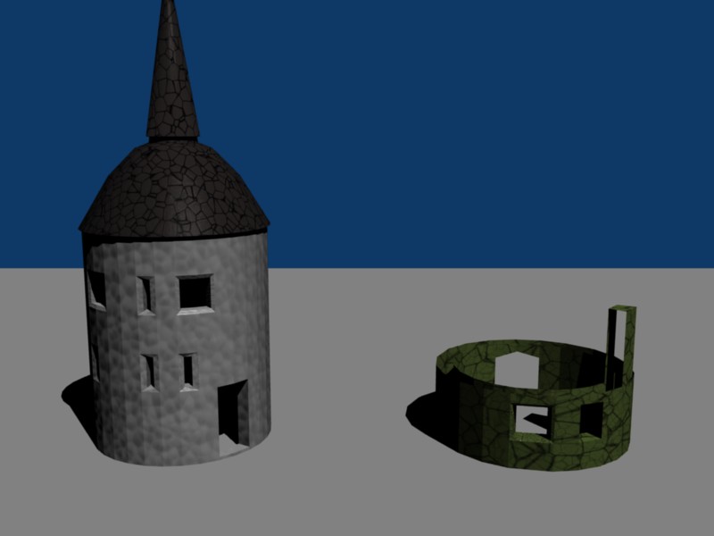
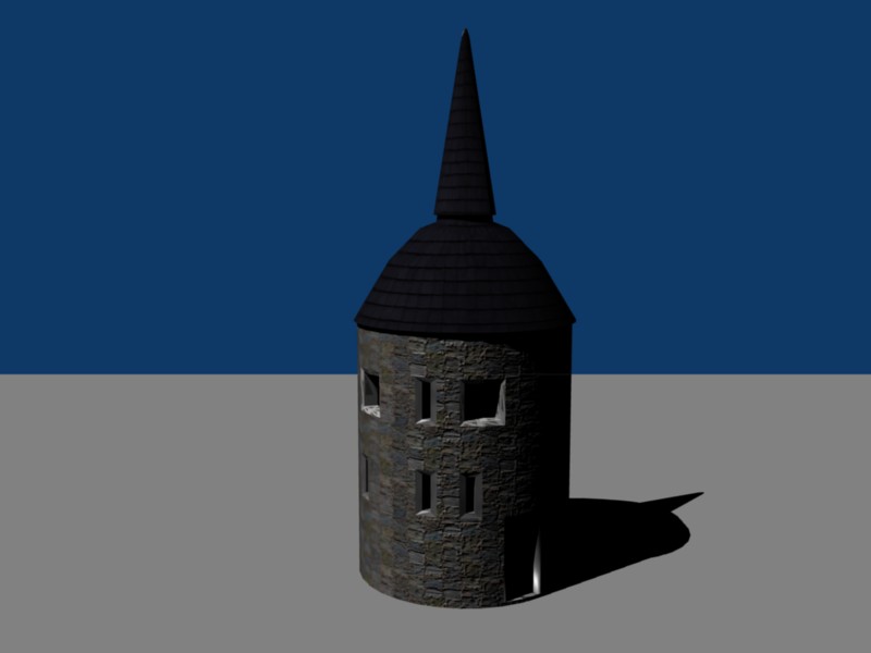
This shows placement of a window. The edges in one of the wall sections were deleted. Then the window was selected (small L with the cursor on a window vertex) and duplicated. The copy was moved down to the wall section (g, z) and then, in top view, rotated to the center of the missing wall section (r, move the mouse).

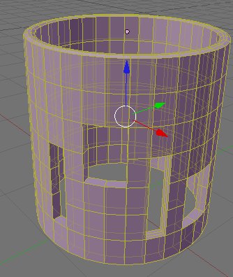
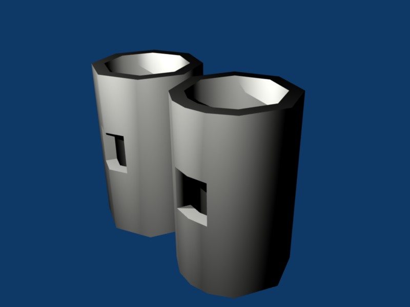
Before deleting any wall sections, I’d make a copy of the whole wall, to use for the sections of the tower where there aren’t any windows.

Wow, thanks for the effort of providing such detailed tutorial! That way I was able to follow it step by step.

In direct comparison to Simon’s method, though, I found yours to be rather complicated. The following image shows what I came up with:

The grey tower was made as Simon suggested, the other one was done by following your method. The grey one was built way faster. ( The inner parts of the openings are modeled seperately).

So as of now I fail to see the advantage of your method, Orinoco :frowning:

Attachments


All circles/cylinders in Blender are made up of n-sided polygons, which the program is then smart enough to smooth out to make a circle/cylinder in render. When you subdivide a line segment that forms a side of one of these polygons, it makes faces that aren’t on the polygon, since the new vertex isn’t on the radius of the circle, it’s on a chord. A picture would demonstrate this so much easier…I’ll upload something when I have some time tonight.

btw, those vertical slots are archer openings. Vertical so he can sight and shoot the bow, but not wide so he himself does not get shot. And for detail, the stone on either side is wedge shaped (wider on the outside, narrow on the inside) so he can angle his shot outward. The slots are placed and the angle of each opening such that he has 360 or whatever degree coverage to be able to shoot any enemy from at least one window. Multiple archers at each level thus can cover any range and any oncoming position.

So as of now I fail to see the advantage of your method, Orinoco

Well, for this project I suppose it’s just a different method, not necessarilly an easier method. One problem I see regularly is when people start with the big forms, they get stuck when adding specific details. Sometimes it’s easier to model the detail first, then build the large form around the detailed part.

Orinoco’s method has merit later on down the road, when you realize you need yet another loop-cut to make some little detail work right. Then you need to do lots of backtracking, vertex-merging, etc, rather than knowing what you need at the outset.

Here’s a mini-tutorial to illustrate what I meant about working with a cylinder. There are lots of steps left out - my free-time is pretty limited - so make of it what you can.

Image 1 shows the creation of a “circle”, in this case a very polygonal one to illustrate the point. Extruding it up (Image 2) and then Setting Smooth, in object mode. (Image 3) Then, I copied it once, and cut a window in two different ways: for the right one, I did all loop-cuts with CTRL-R, the left one, I deleted a column of vertices, and then did an extrude (in plan) and rotate, filling the last faces in with the F-key. Image 5 shows the result of doing a version of what enzhflep suggests above, an extrude-region in plan, followed by a Shift-Z (xy-plan restrained) scaling to give the wall depth. I then apply the edge-split modifier. The rendering is image 6. Hopefully, all of this makes sense. The plan views tell the story, I think.

Attachments


That’s true, been there myself. Thanks for teaching me your method! :slight_smile:

That’s true, too. Actually, those openings are probably built for cannonns (the big ones) and rifles (the narrow ones) because there are conduits or whatever the technical term is, like a chimney for the smoke upon firing.

Attached you will find a render of my progress so far. Don’t shoot me for the roof: It is drawn that way in the original drawing.

Attachments


Looks like the arrow loopholes, or rifle loopholes, are beveled inward. They shouldn’t be. The beveling would allow a ricochet to enter the slot, thus giving the enemy a larger target (anywhere inside the bevel, not just the actual opening.) The overall proportions seem off, as well. The reference photo shows a tower that is as wide as it is tall.