This is my first post so be gentle! Any help/advice/critisicm is appreciated, I am new at this.
I am trying to create a 3d model of a headlight bracket for a car. I thought the easiest way might be to model the projector and then use the boolean modifier difference to create a tight-fitting bracket that I could 3D print.
So I modeled the projector but the difference modifier is not behaving. The projector is a pretty complex object and I extended the bolt holes as cylinders so they would “punch” through another object. I checked the normals to the best of my ability (which is small) and they look ok.
I think the problem lies in the way that I modeled the projector. I created a bunch of simple objects and then used Join to coalesce them into one object. This means there are a lot of vertices “inside” the object. It is not a simple shell, although having it as a simple shell would be good. I’m pretty sure that I did not do the easiest thing with respect to creating this complex object and now I am asking if it can be fixed, or if I should just start over and use some better method of “join”-ing these things together…
My advice when ever I see this kind of thread is; never use booleans ever. Many people use booleans to try to save time, the trouble is that any time you save you will lose in mesh cleanup as soon as you try to subsurf or animate your object.
If you upload an image that you are working off of I may be able to do a quick video showing how to do what you are trying to do.
when it comes to 3D printing in my experience Blender is only suitable when it something like a sculpted character or the like. If your printed model has to fit into something else your best bet is to use a program like MOI which will always print nicely. The trouble with Blender is that the STL exporter does not use the industry’s scaling standard. Thus when your printer gets your model he will not know what to do with it. with something like a sculpted character you can just scale it up until it approximates the dimensions that you are hoping for. With a headlamp bracket every dimension has to be perfect or all that time and money is just gone.
That is kinda a bummer about not using booleans… It seemed like the perfect fit. Also, I will not be animating this or using subsurf-ing in all likelihood.
As far as the 3D printing that is really good to know. I am using the metric measurements in blender (2.6) and taking furious measurement from the real-world pieces that I am modeling to make sure things are right. I was really hoping that I could have this piece printed…
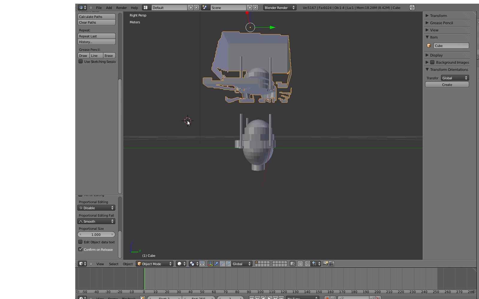
I included a couple of pics below, the first one is (most) of the original bracket off the car. There was more on the back originally, I cut it. The only part that really matters are the three holes around the perimeter. Those attach the projector to the headlight housing adjustment mechanism. The other two pics are the projector housing that I have modeled. It is called the FX-R, hence the filenames. I already included the blender file up top with the model in it.
At this point it would be pretty easy for me to take the model of the bracket (that I already have, I’ll attach it later) and then size it down to match the FX-R. Any help you could give would be great.
Here is the model of the bracket that I already have. It is not on the same scale as the FX-r. The measurements in the FX-R model are (painstakingly) precise for the four bolt holes (that I have extruded into long cylinders in the model… ).
Have you ever used the online 3D printing services? I was thinking of using shapeways because it seems they natively support blender and so I was hoping that I could get accurate measurements.
Yes, I am trying to make that FX-R projection housing (the aluminum thing with a lens), “fit” (i.e. bolt up to) the bracket (img_4031) in the first image. The bracket is the “chrome” and green thing, the projector is the thing with the lens and wires coming out of it.
All I am going to print is the bracket. I would like to be able to bolt up the existing FX-r projector (the thing with the lens and wires) to that bracket that I just printed out. Most people just do this with hot glue and homemade adapters made out of wall hangers and JB-weld, but I wanted to do it right…
For this application you will definitely want to use a CAD/CAM nurbs modeler. Blender is awesome and it can 3D print but that connection between Blender and the 3D printer is not a reliable one.
Sorry I haven’t replied in a while, I got sidetracked with real life.
Thanks again greyoxide, can you suggest any CAD/CAM modeling software that I can get for free? This is the primary reason that I am using blender. I would like to be able to model small parts like this more often in the future, but I cannot make an investment in something like AutoCad at $3000+ or really MOI at $300. Is there any hope for blender?
RickyBlender, the bracket has three holes where it attached to some scaffolding inside the headlight assembly. Those are not the holes that will be used to attach to the projector. I am trying to model a bracket with the three holes that you see (so it can attach to the headlight assembly) and the four new holes (preferably in a sort of parenthesis shape to allow a little rotation) to bolt up the projector.
I am still working on this, but progress is slow because I don’t have a lot of time for it.
GreyOxide, I think I’ll just start modeling the bracket and then use the FX-r model for fitups to check if the holes would line up.
I think the boolean operations of Blender are pretty powerful. I was at the same stage once, and there were 3 reasons why the booleans didnt work. One time the object was not watertight. Next time not all normals pointed outside. And then I had a case where I had a parent-child relationship between 2 objects I wanted to boolean/difference from each other, and that seemed to block a proper calculation.
My experience so far is: if the object has been properly defined (watertight, all normals pointing outside), then it works very nicely.
I have questions as well regarding the advantages/disadvantages of the boolean modifier. In my case, I’m trying to build cogs for a bicycle drivetrain. Within blender, the one sure way I’ve found is to cut circles with spheres using the boolean. This way, I’m able to make the cuts a consistent size, making a consistent array with the sphere so the cogs are in correct proportion to each other, with a set number from one cog to the next. Then I want to make a chain.
Is there a better way? I’m working on a laptop, and have seen that Boolean takes a bit of sweat from the CPU. Will that come into play during a render later on?
As far as CAD, I recommend taking a course from a community college, and getting a student license (I’ve done it before, and plan on doing it again soon, some things like this I want to do just seem much easier with AUTOCAD).
 Any help/advice/critisicm is appreciated, I am new at this.