Hi, all. So I’m working on a 3D model of Disneyland in Blender, and one of my tasks at the moment is building an earthen berm that forms part of the boundary of the theme park. I have a specific outline for this bit of land; retaining walls hold it on some sides, and other sides simply slope down until they meet concrete. I’m planning on building the mesh and then deforming it vertically by using a height map. The thing is, I can’t figure out what the geometry of the mesh should look like. I’m not very experienced at organic modeling, so I would really appreciate any help.
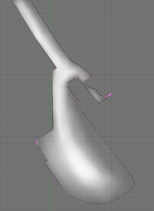
I guess ideally, I’d like someone to draw where they think the edge loops and so on should go on the attached image. It’s an overhead view of the mesh’s outline–the top is incomplete–with a rough height map Screened on top of it for your reference. I just can’t figure out what would be a good way to set up this mesh.
Thank you so much in advance! I look forward to hearing from all you expert modelers.
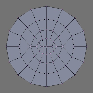
ideally you want lots of nice even quads, like a grid. you also want the mesh topology to reflect its eventual form, so if you are going to put a little hill somewhere, you want the edge loops to follow that general contour. so probably somewhat circular, for a hill. if you are going to have a stream, the edge loops should, in general, follow the contour, as it winds about. avoid triangles and skinny faces, and also quads that are ‘bent’ at extreme angles.
Thank you very much! These should be helpful, though translating them from round forms to the linear forms of my project may be difficult. Also, I still don’t know what to do about the indentation at the lower left of the shot I posted. See what I’m talking about? I’d really appreciate it if some enterprising soul could draw a rough idea of what the mesh would look like around there.
Ooh, thank you! Very good stuff that I should be able to apply to the model. I’m not going to have a problem with the technical aspect of actually creating the points, but may I ask what your process was for creating these examples?
well, I used several different techniques, extruding, and multi-loop cuts mostly. also, you can add an object in edit mode, and use the geometry from that, like, for the rounded edge, I started by adding a circle, while still in edit mode, and then deleting the bits that i didn’t need, then scaling it to fit, then welding it to the rest of the model ( select two points and alt M ).
 I’m already pretty aware of all these goals, but there are a couple of things that make achieving them all difficult: