Hello,

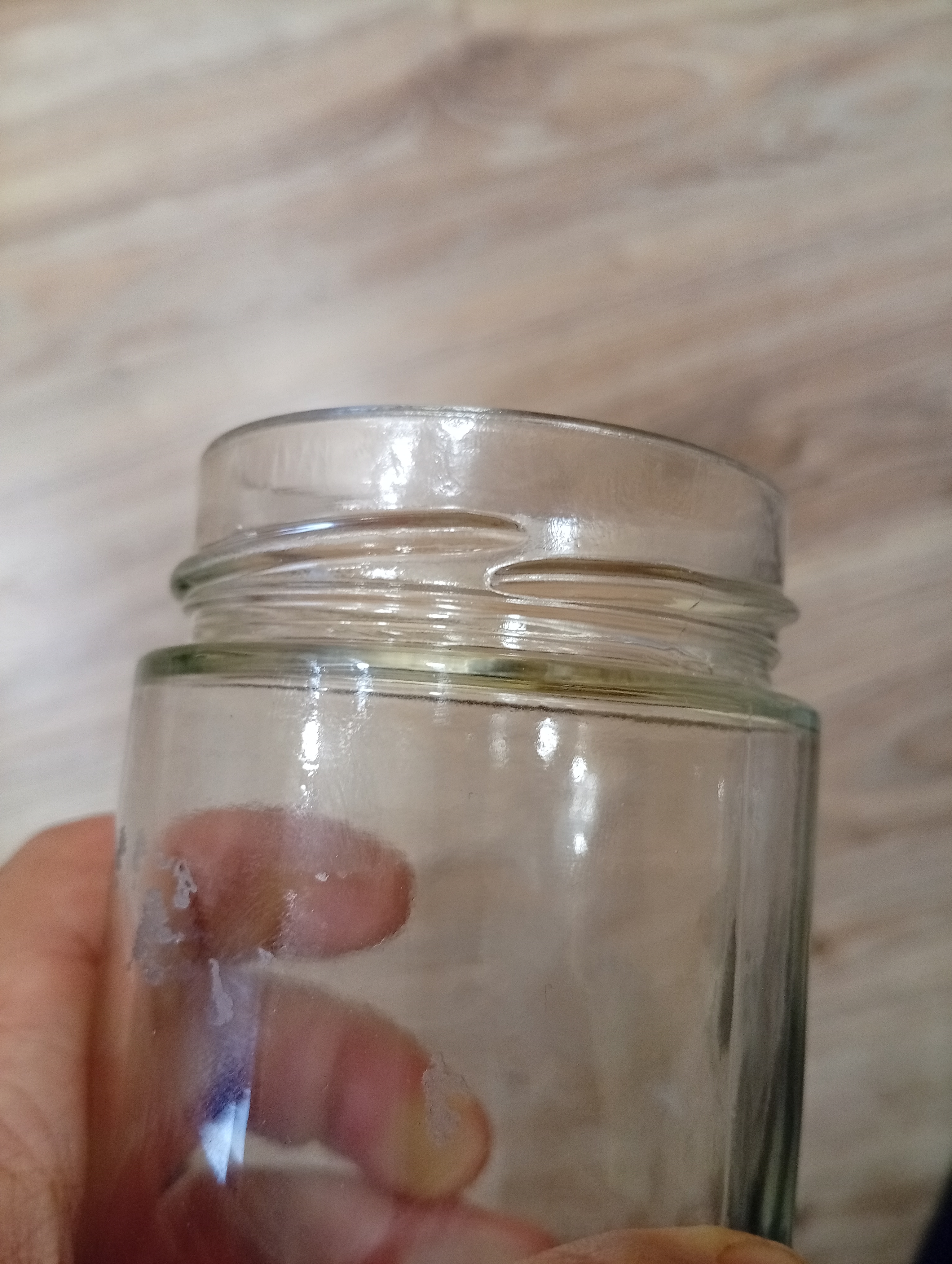
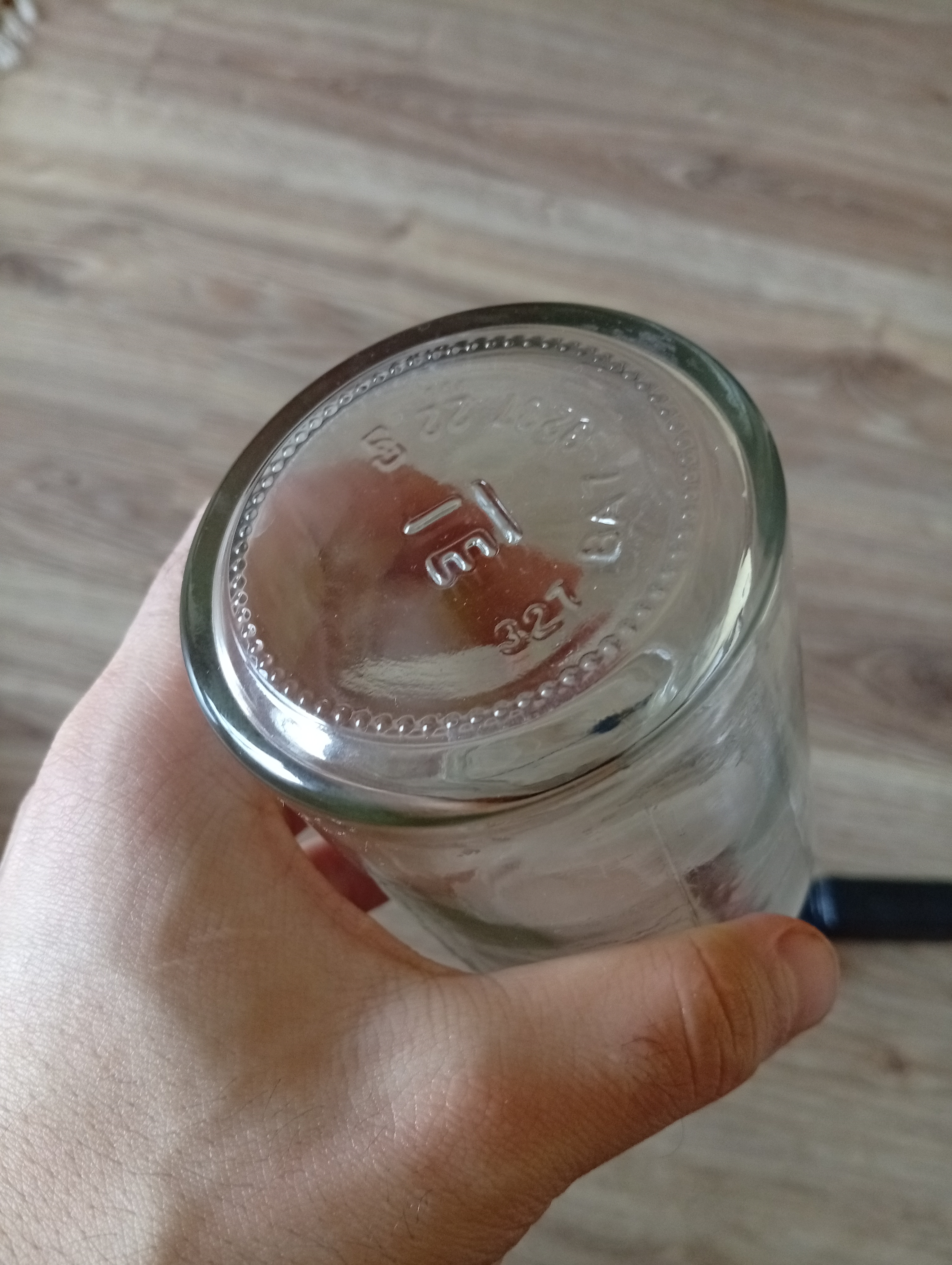
How would you model a thread like that? With good topology? It is called a twist off used on jars mostly. It is not a continuous thread like the ones used on bolts. It has cust off segments of the screw.
I have tried modelling it for the past few days with no great success. Either I get a very bad topology with artefacts or very tedious to do. Is there a quick, efficient way to do it? Also can it be done non destructively?
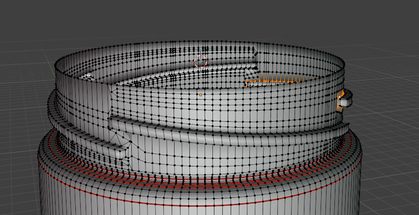
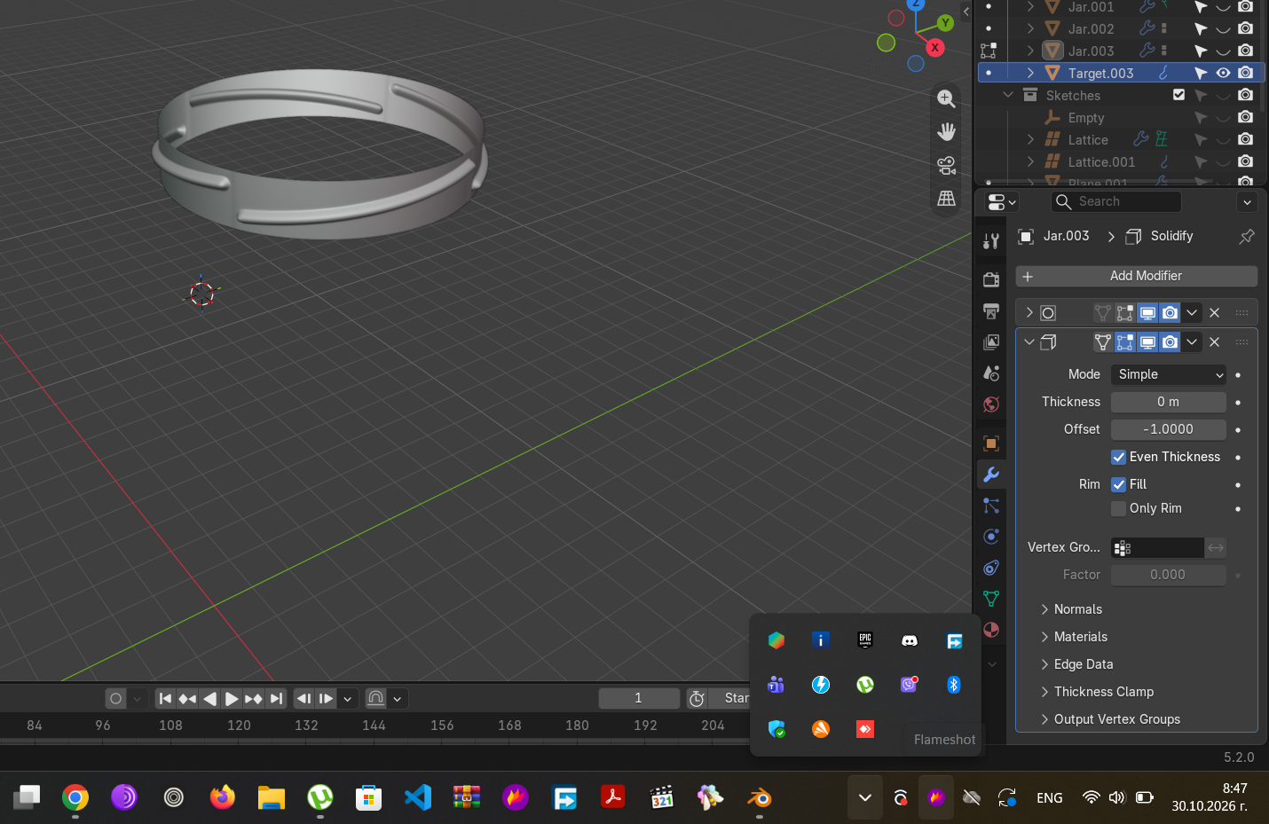
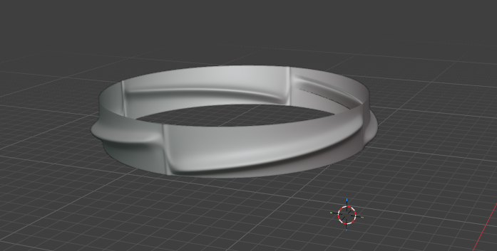
One of the main things I want to do is model it like it is on the physical jar. The segments overlap each other so that they can hold the top of the jar tightly. The ends of the twist off segments are overlapping on the vertical axis. I want to do that.
I have tried doing it in several ways:
1/ Using a flat surface and modelling a single twist off segment. Then putting a latice modifier that has been shrinwrapped to a cylinder with the exact dimensions of the twist off part of the jar. The problem with that is that I cannot use array after that without applying the modifier. I get weird results if I do that. So I apply everything and then do a spin in Edit Mode on Z axis with duplicates on 360. The clean up though could be very tedious and not artefact free if I want to do it with overlapping segments.
2/ Using a flat surface and modelling a single twist off segment. Then using an array with 4 segments. Then putting a curve modifier and using a bezier curve circle that I got from a mesh circle (convert) from the original cylinder of the jar twist off thread (with exact dimensions of the jar neck). I was able to do it but again very tough to work with and not a good result.
3/ Using a flat surface and modelling a single twist off segment. Then using an array with 4 segments. Then simple deform - bend 360 degrees. Not able to pull it off. I know this tool can be confusing some times. In this case it just bends the segments not the walls of the jar neck.
4/ I have tried on cylinder surface as well. Modell the segments on a cylinder surface but full of artifacts as you might expect even with higher subd.
5/ I tried Method 1 but with Boolean with the segment part but clean up is monstrous.
6/ Again method one but with knife project on the surface of the cylinder and then bridging the segment and the cylinder of the jar neck. Hard clean up.
Additionally what makes it hard is that you do not know how big or how many faces you should make the flat surface that you create a single segment on because when it is latticed or curved with modifier, it stretches, sometimes even to a different extent in different areas. That makes it hard to control when you use spin tool on 360 and then the clean up is tedious. The thing is that you can flatten a fourth of the circle but that is not the same as unwrapping/flattening a segment of the circle and keeping its are. I have idea with that - I saw a video from Default Cube on how to do it with nodes. (How to Flatten With Vector Displacement (Blender Tutorial) . I haven’t tried it yet. Also another option I saw that could be a potential solution is using a method from this video:
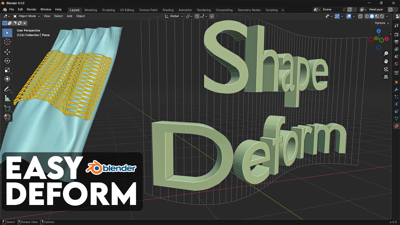
I will try them these days but I would appreciate if you give me other ideas or workflows how to fix that.
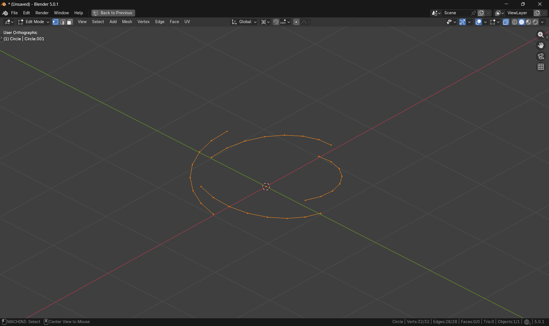
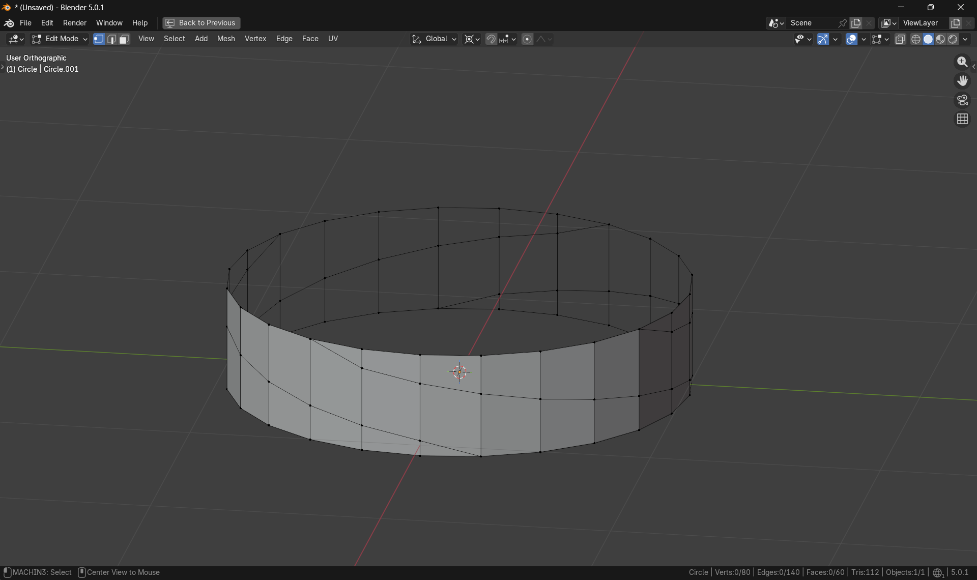
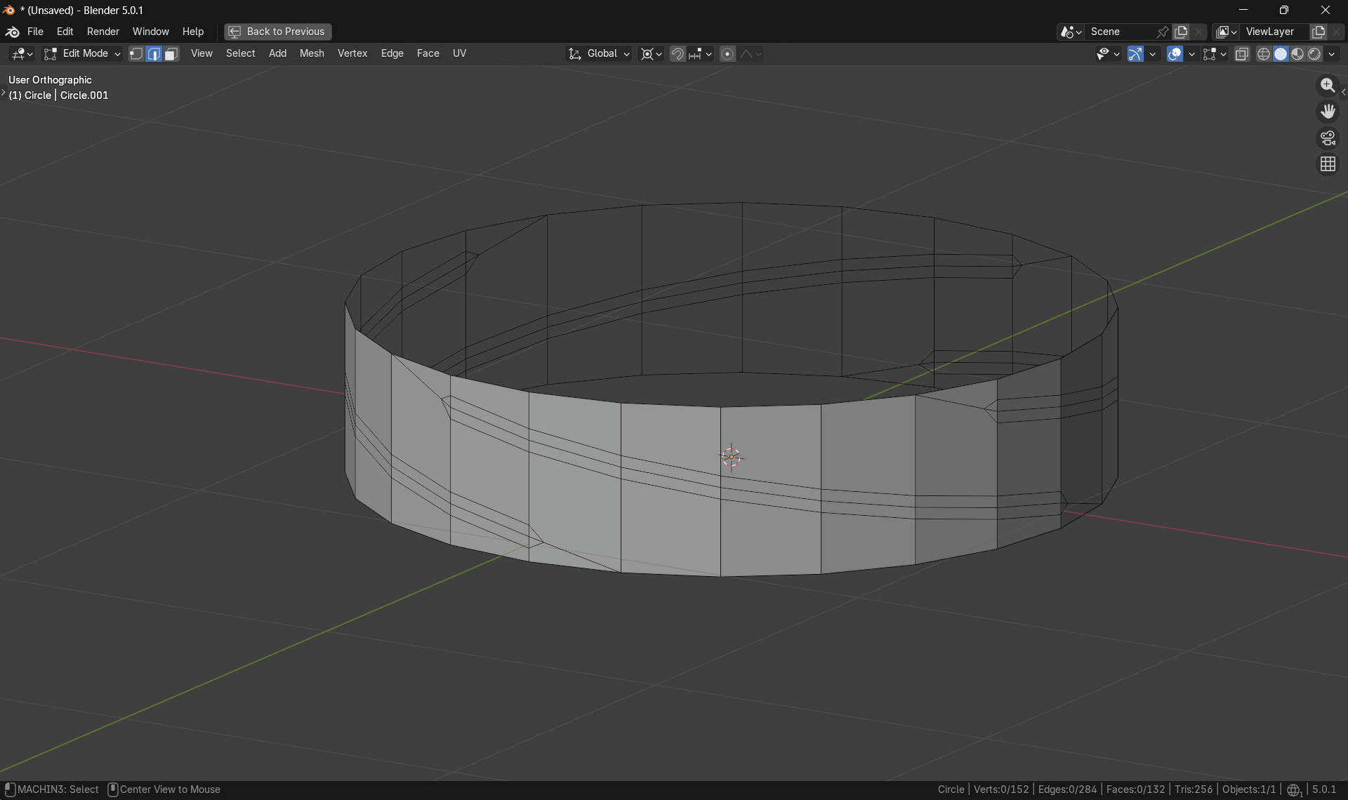
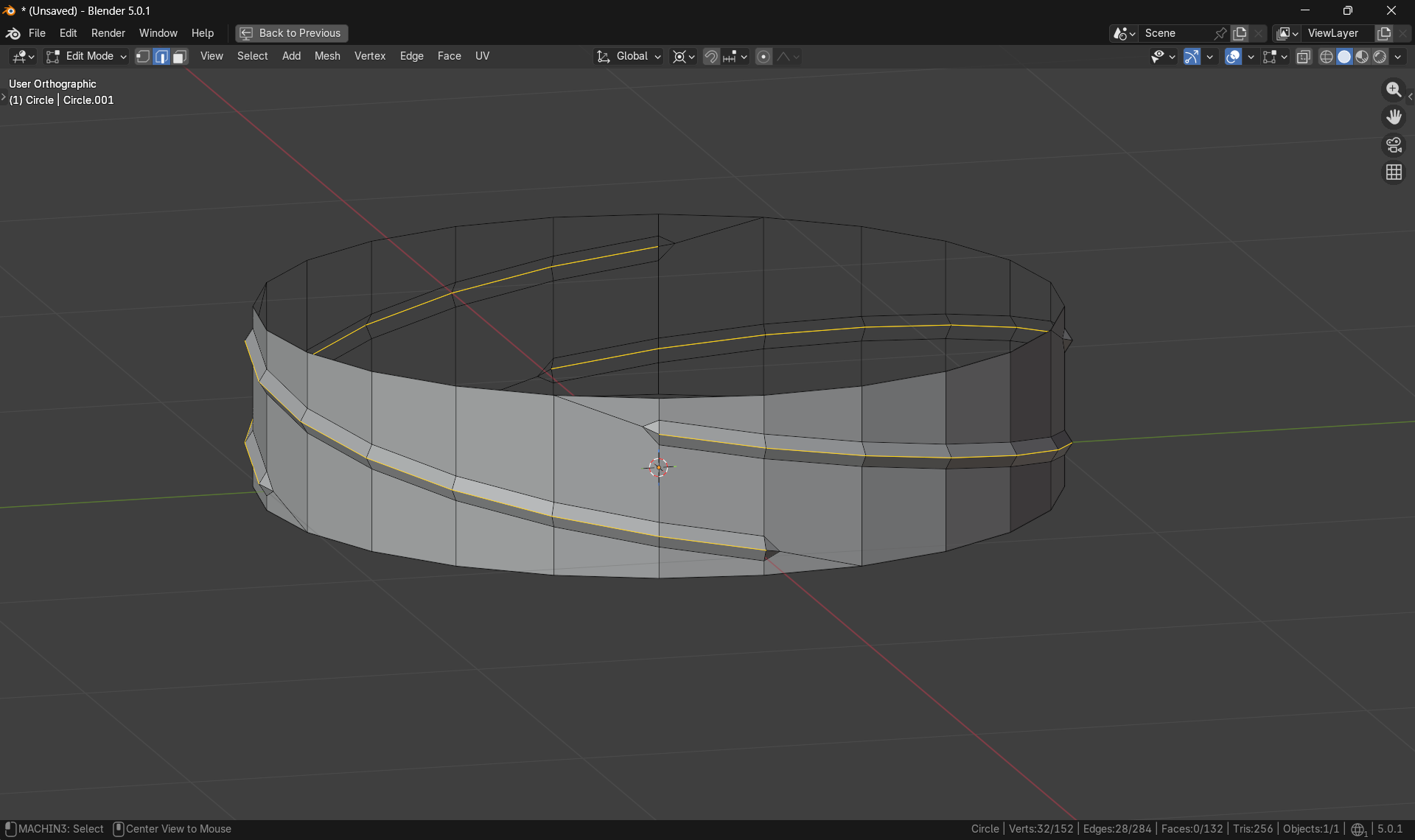
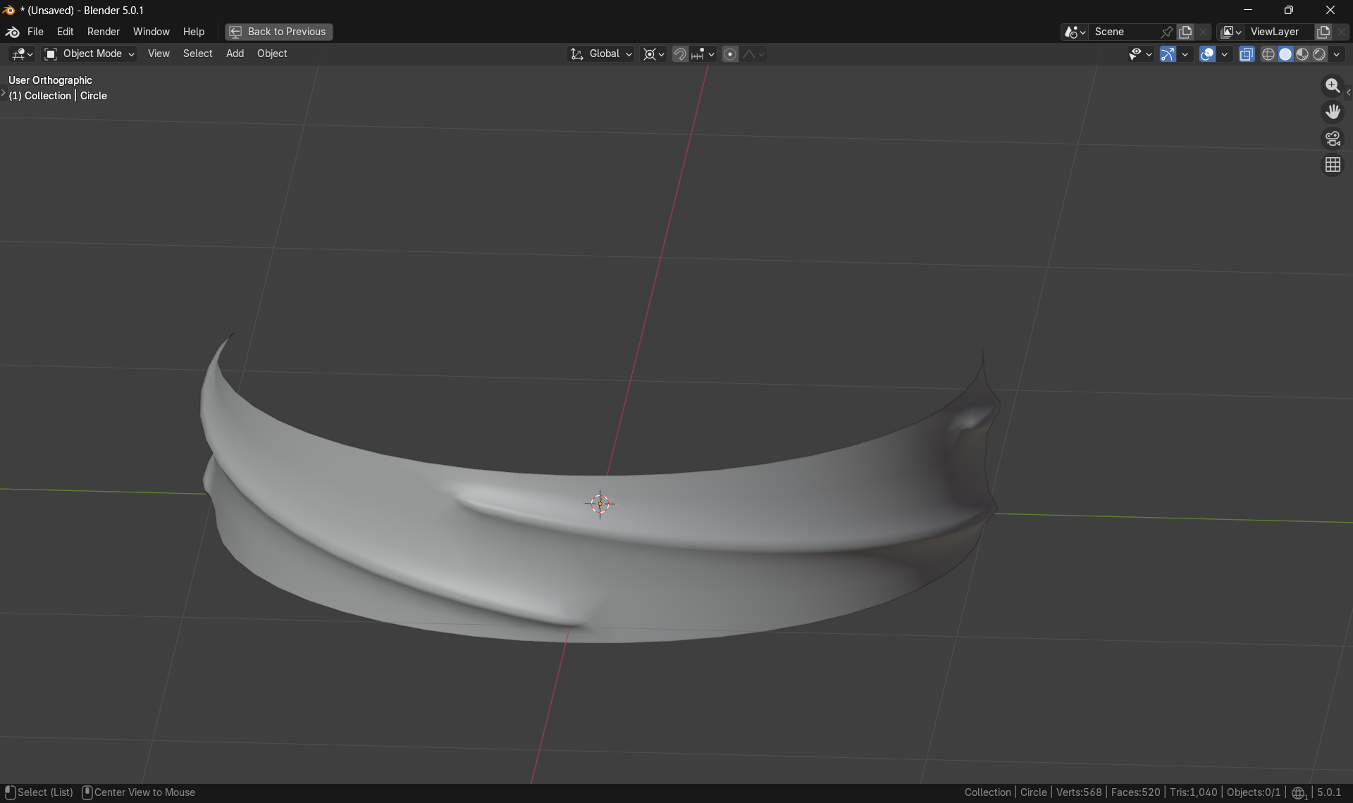

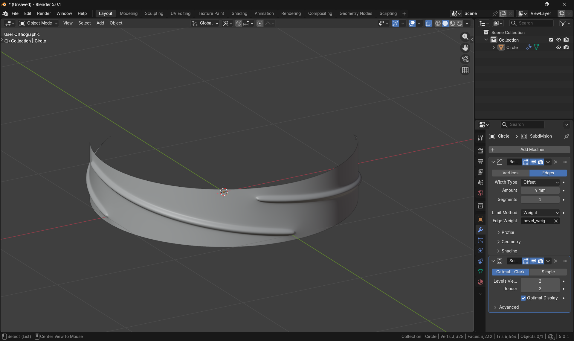
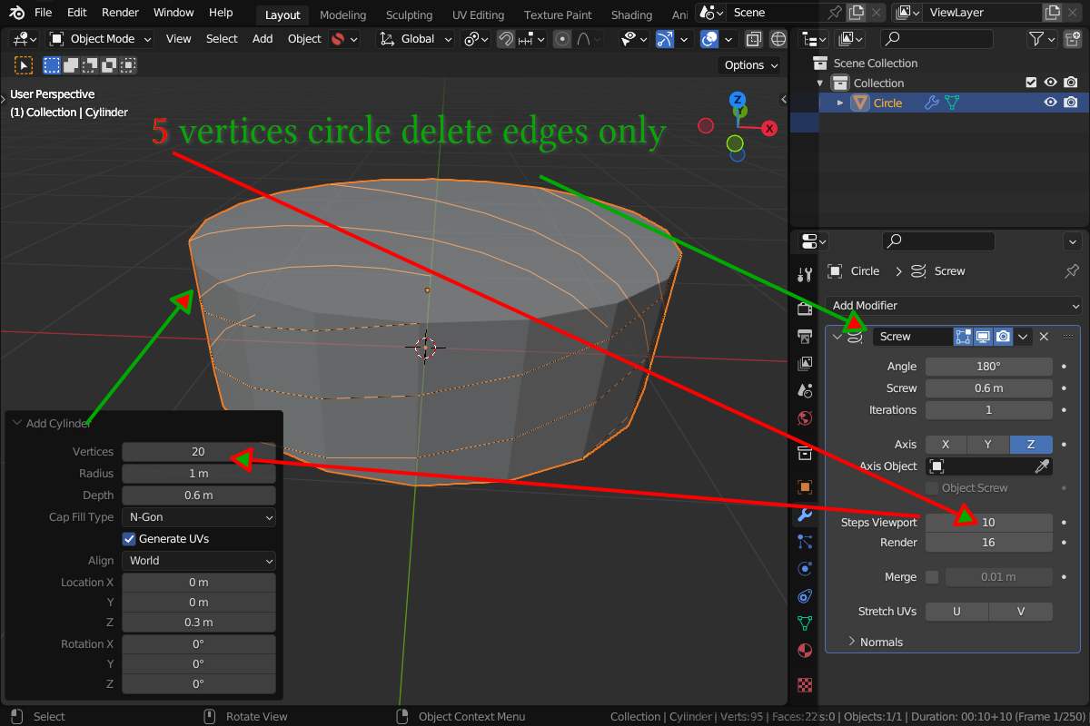

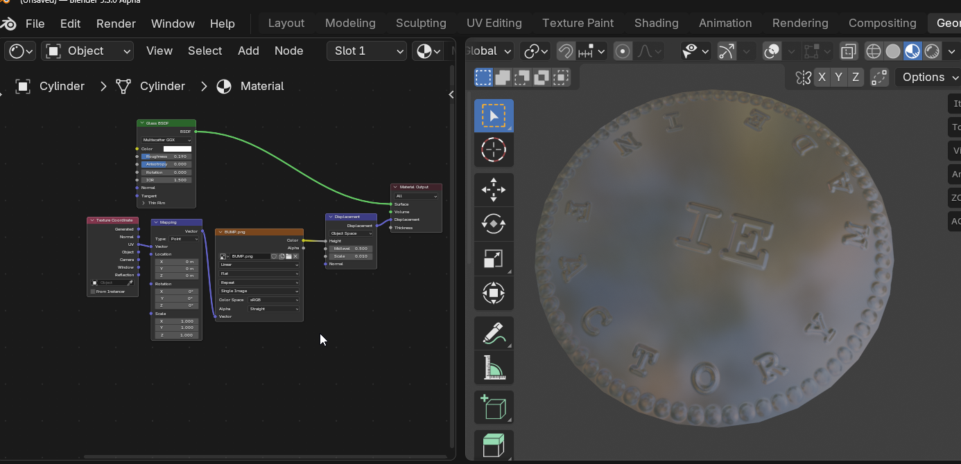
 :
 ..