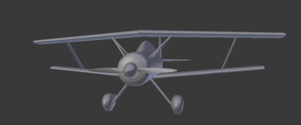
i’m new to blender i have been working on modelling a light biplane home built aircraft that i have designed (and hope to build for real too!!) here are some screen grabs
i hope to add much detail and render this model at some point but at the moment i am trying to use the aircraft geometry model as the basis of a CFD mesh in order to analyse the aircraft’s aerodynamics.
Hey, that’s a cool blender model you got(needs more work for an actual art piece though), but lets talk about the real life aspect…
What program(s) are you using for the CFD analysis/Structural Analysis/Stability Analysis/Power Requirements and so on…?
And the title suggests a question…but you have not asked one…
btw, scale the airplane down, if your are modeling to build, this should be an accurate model, thus remember 1Blender Unit = 1 meter (better yet switch to metric units in the scene tab (on the button toolbar next to the camera picture)
thanks! it’s pretty rough at the moment. The basic aircraft geometry has been created using the NASA vehicle sketch pad which is useful and easy use software for the basic modelling and conceptual analysis and design of aircraft and other vehicles. (More info on it can be found here www.openvsp.org/) Vsp will export models in STL file format which i have then imported into blender. VSP is fairly limited as a 3d modelling tool so the detail design will have to be done using blender.
At the moment i am trying to edit and clean up the basic aircraft geometry and use the mesh as a basis for a cfd mesh that i will then analyse using OPENFOAM an open source CFD solver (more info here www.openfoam.com/ ) once i have done some aerodynamic analysis i will then design and analyze the internal wing and fuselage structure using the open source FEA software calculix (more info here http://www.calculix.de/) as far as stability analysis goes i am an aero engineer and will probably do that analysis by hand based on the outputs provided by the other software. The aircraft has been designed around the ROTEC r3600 150 hp radial engine (more info here www.rotecradialengines.com).
anyway i had two questions regarding the mesh, First of all how do you intersect and delete internal parts of the mesh. for example how do you delete the parts of the strut that protrude into the wing or the parts of the lower wing that protrude into the fuselage? the second question is how do i smooth out the plan form outline of the wing without distorting the shape of the airfoil cross sections?
if i use the smooth vertex function on the elliptical wing it appears to distort and shorten the airfoil cross sections. Alternatively how could i take an airfoil section like the one above and extrude it to produce a smooth elliptical planform wing (eg like a spitfire) whilst keeping the exact airfoil shape (the airfoil can be scaled up or down in size)
To convert these triangular faces into quads - use [Alt]-[J] (it is a shortcut to the Mesh->Faces->Tris to Quads command).
However, you have plenty of them.
Maybe a different approach will produce a better results (i.e. on the rendered picture): use the imported mesh just as the reference, then create from the scratch on different layers a much more simpler mesh, smoothed by the Subdivsion Surface modifier?
(I do detailed models of the airplanes in Blender in this way, see for example here). You can treat the mesh smoothed by the subdivision surface as something close to the NURB surface (the mesh vertices play in this case the role of control points). However, with such a mesh you still have to approximate the airfoil shape (usually it takes about 20 control points to approximate it with a tolerance of about 0.001%)
DDD the programs you mentioned (Avl Xflr )use panel method appoximations that are useful for calculating things such as the amount of lift and drag of an aircraft wing but they do not take into account viscous effects and such and are not very useful for applications outside of aircraft design. OPENFOAM and commercial software such as fluent are full 3d flow solvers and are much more powerful tools which enable you to do such things as drag minimization and can be useful for all kinds of aerodynamics and fluid dynamics applications. i guess this project started because i wanted to teach myself CFD and i wanted to design an aircraft. Software such as fluent and OPENFOAM are probably overkill for a simple aircraft project such as this and developing a design workflow using this software is proving more complicated and time consuming than doing it all by hand using pencil, paper and pocket calculator but as i said they are powerful engineering tools that are available freely and are definitely worth persevering with. i have started off with a more conventional design which will enable me to easily compare and benchmark the CFD results with hand calculations and older text book methods to ensure that OPENFOAM produces valid results. i am hoping to use Openfoam as a “digital windtunnel” that will enable me to investigate more unconventional aircraft designs i have been thinking about.
And it most certainly is going to be a real full size light aircraft! my background is in engineering and aircraft structural design i have some catia experience but not much blender or complicated 3d modelling experience and have had to teach myself blender too. The hardest part so far is getting accurate and quality aircraft geometry (particularly the wing and tail airfoil sections).
Witold thanks for your tips! i looked at your site, your P40 model is excellent! was that built from factory drawings? (i believe they are available from ebay on disc) i dont know what your background is but your model looks to be better quality than a lot of cad work i have seen from professional engineers. when will your book on meshing aircraft be available? i think it would be very useful to me!
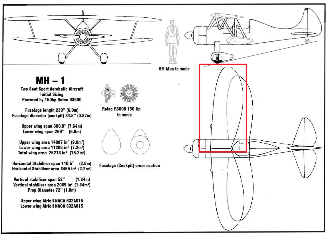
anyway here is the original scale 3 view drawing i created for this aircraft getting a nice smooth elliptical plan form wing composed of accurate airfoil sections is proving somewhat difficult for me
Also here is a large database of aircraft airfoil section data that might be useful to other aircraft modellers. http://www.ae.illinois.edu/m-selig/ads/coord_database.html there is a large number of airfoils in .dat file format, is there anyway to import this data into blender to use as the basis for a mesh?
Once again thanks for your help!
try to make your model with as many quads as you can
its’ easier to add remove loops afterward anyway so make you life easier too!
also any idea on how long it takes to run a CFD sim on openfoam for such a plane ?
i’v see one script for making wings shape but look’s like there are many data structures for wings in think!
and the script cannot handle all data types!
happy blendering
thanks yes changing everything from tris to quads has made everything easier…it took me a while to figure this out. as far the time required to do a cfd run on open foam the correct answer is it depends. for subsonic incompressible flow (light aircraft) with fairly simple geometry it shouldnt take to long to get some useful data. as you get into transonic and supersonic flow (fighter jets and passenger jets) things get a bit more complicated and require more processing power and time.
The scale modelers used to say that there is always at least one error, even in the best model…
i think this is just as true for the real aircraft too… having talked to people involved in restoring aircraft like p51 and p 40 and having done a fair bit of maintenance work myself i can say that no two aircraft are exactly the same even if they are the same make and model and are constructed in the same factory.
one idea i have for a modelling/engineering project is to purchase the set of P51 mustang plans from ebay and use these as the basis for constructing as accurately as possible a 3d mesh (including all airfoil data) and use this to perform a cfd analysis of the aircraft. this will provide overall lift and drag co efficients and stability derivatives which you can then put into a 6 dof simulator code which will produce results that can be compared against extensive wind tunnel and flight test data that is available via the nasa technical reports server.
(These *.dat files describe many vertex points, such a dense mesh is not practical in Blender)
i think this is the root of my problem with modelling the wing. here is my latest attempt at accurately modelling the elliptical planform wing as you can see the mesh is very dense and somewhat impractical.
However, I suppose that the best use of such a contour in Blender is using it as the reference, matching the original airfoil with a subdivision curve, which control mesh contains just a dozen control points…
is there a guide that describes this process for a for a beginner ?
thanks
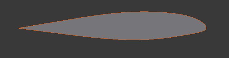
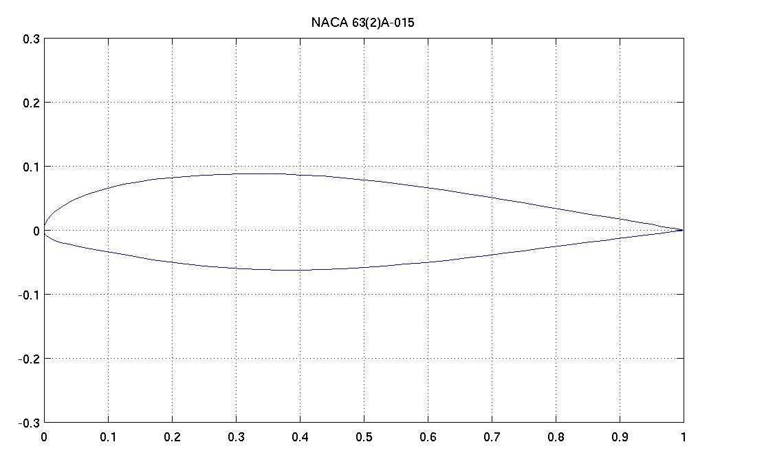
the above image is a NACA 632A015 airfoil which is used on many light aircraft. these airfoil sections can be imported in .dat file format (from the website linked to above) but they consist of a large number of vertex points. when you extrude these sections it produces a very dense and difficult to manipulate mesh.
continued below
what i am trying to do is to produce a nice curved elliptical wing (similar to a spitfire wing) that is composed of accurate airfoil sections that can be scaled up or down but must have a consistent shape. i am trying to smooth out the jagged areas outlined in red here
the reason the airfoil sections need to be accurate is that i hope to use this mesh as the basis for an aerodynamic analysis using CFD software to produce something like this
i guess the question i am asking is how can i reduce the number of verte points in the airfoil cross section without loosing definition in the airfoil shape?
thanks for your help
bugsy
Just select the points you want to keep… but the more you remove the less defined the airfoil would be… so use your own judgment on how much is enough…
In fact, it will be described in the Excerpt II from my book (it should be available in February). (I uses the process of forming the wing as the basic example to teach how to model in Blender. [SUB]It has been already described two years ago in the previous edition of this book. Unfortunately, that edition was in Polish, only. However, its illustrations can give an general idea of the proposed process. Look first on pages 592-594: they describe how to obtain an exact 2D image of the airfoil. Then this image is used as the reference on pages 113-115, to fit a subdivision curve into this shape[/SUB]).
DDD is right: the key point is in the acceptable tolerances. They are different for the “pure artistic rendering” and for the cfd software. Your airfoil seems to be laminar, which means that the tolerance should be much tighter than for the conventional shapes. However, I think that it is still possible to draw an exact reference image, first, then fit it in Blender with a subdivision curve. It may require maybe not 25, but 50 control points. Then it will be possible to export such a “dense” result mesh (vertices of the subdivision surfaces) into a format required by the cfd software - if you need such a “reversed” workflow.
what is the data format for this wing file?
there was a little script that could read some data
but not certain if it can read your data for this wing?
i’ll try to find the reference thread on this and be back with it
but you CFD soft should give an idea on what kind of resolution you need for your wings data
then you can use this to defined the wings!
I’ve been pretty busy so there hasn’t been much progress on this in the past few weeks. But i have posted the original VSP model of this aircraft to the VSP hangar if anyone is interested in downloading it. you have to download and install VSP to open the model and then you can export an stl file that you can then import into blender. link is here http://hangar.openvsp.org/vspfiles/130
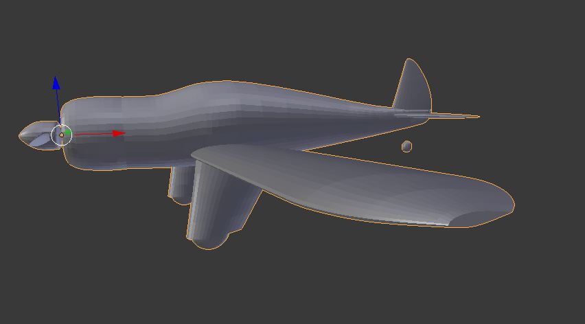
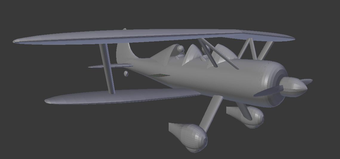
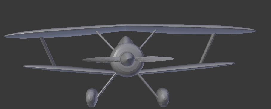
hi all its been some time,still slowly working on this project its grown as these things tend to do. i have generated several other concepts as well. here are some


 and a lot of bookmarks to put. Thanks and good blending (and fly I hope)