How to create your custom angular maps?

Hi!

I would like to create an angular map to be used as the world background in a Blender scene. The scene has a cartoonish feel so it would be best to paint the image in Photoshop by hand. The question is, does anyone know how to then convert a normal drawing into an angular map (so that it maps correctly in Blender)? Are there any tutorials on creating angular maps?

Why use another program for a typical 3D-task if Blender is specialized in 3D? The basic idea is to use a lamp as a fixed projector for any quadratic shaped picture you want to convert. This picture is projected on a 100% reflective concave shaped half of an UV-Sphere. You will find the result for a quadratic test pattern as well as the .blend-file as an attachment.

Because the projector-lamp is fixed, one has to adjust the diameter of the sphere as well as the camera position depending on the pixel count of the original picture. I made an animation for this relation. The lower frames are for low-res pictures, the higher frames can cope with high-res pictures. Frame 85 is a good combination for a 2048x2048 px. resolution. The blend-file is set up to load the original file via the lower window on the right side, the output-resolution for the map can be adjusted through the upper right window.

HTH Ulf

(This is may first post on this site so there might be a chance that I am messing s/t up while wrangling with the editor)

Attachments


MatCapBuilder_Blender2.5.8.blend (1.05 MB)

Thanks for posting the BLEND file but I don’t think it actually makes angular maps. It just projects a square image into a hemisphere. There is more to it than that.

Here the result of your output:


Now If I use that as an angular map in Blender I get this…


A correctly generated angular map produces no stretching.


Hi,
could you pls. explain what “more than that” is meaning.

Angular mapping is IMHO the mapping of a sphere against the normals. I.e. if the normal of a vertex is pointing directly out of the screen towards yourself, the very center of the map is selected, If the normal is pointing 90° upwards the top pixel will be selected, if the normal ist pointing downwards the lowermost map pixel would be selected. An because the mapping is limited to the visible normals you will find a angular response to each and every possible normal. Just think of a styrofoam ball you want to spiked with tooth-picks.

And because these maps are translated from an ideal sphere you will get stretched pixels if the mapped mesh differ tremendously.
here is how Suzanne looks, when mat-capped with the landscape texture:


An here she is from the backside:


I used the GLSL-shader in the 3D-view and it works for me at last.

Because of the landscape-picture itself the mapping isn’t quite as obvious as it is with the test-pattern I posted.

Cheers

Grrr - i can not edit the previous posted file .
(It seems that editing a file with attachments is not possible)
I found four(!) typos:

“And because these maps are translated from an ideal sphere you will get stretched pixels if the mapped meshes differ tremendously.”

“I used the GLSL-shader in the 3D-view and it works for me at least.”

And because the mapping is limited to the visible normals …”

"Just think of a styrofoam ball you want to spike with tooth-picks.

Sorry

Your blend is basically projecting a rectangular image on a sphere, that is not an angular map or a more often found under the name lightprobe.

The only proper way to produce a lightprobe digitally is from a cubemap. You can create a cube, use the cubemap on it, place a reflective sphere in it, and render a frontview of the sphere.

You might get a good result if you take a rectangular image, map it on a convex hemisphere and place a sphere in front of it with the camera between. Then the mapping would be more accurate, yet still wrong.

This happens with the .blend below, projecting a “cubemap” on a hemisphere:

The .blend:
http://www.pasteall.org/blend/7348

Personally I find angular maps quite useless. They are only good for reflections or IBL in my opinion and they have a low resolution by design, because they are for reflections or IBL. If you use high res images for IBL or reflections it gets all grainy.
It´s blenders fault for not using spherical maps properly, as I consider them state of the art. They are made by stitching lightprobes together.

Spherical maps come usually in 2 resolutions, a small one for IBL and a big one for the background. And then you got a 360° background.

If you get a spherical map you like, you have to create a grid, map the spherical map onto it, make it a sphere with the warp modifier and use it like I used the cube in my above sample and project it on a hemisphere. Delivers you a perfect lightprobe, or half a spherical map.
Actually I could do a .blend that can do that just by loading the texture. I´ll post it up once I am done.

Already done.

The .blend contains the wireframe sphere. You got to load a spherical map as texture for it.
The camera is locked to the right distance and in the z direction. you can move it freely it will always fit, you got to remove the keyframes though, or overwrite it.
I included 8 frames, in 45° steps. If you “render animation” you get 8 angular maps from the spherical map.

The file is 5mb and includes one lowres (lighting) spherical map from openfootage.org.
http://www.pasteall.org/blend/7352

@arexma: The outer sphere in your file needs to be infinitely scaled up for an accurate map.
Plus you could scale the chrome sphere down to get even more of it in. But it is still distorted.

@OP:You could just use the outer sphere , centered at your camera all the time, and large enough to to include everything in the scene.

It’s of no use when you want Image based lighting or something like that ( or maybe disabling shadows for it is a workaround), but it makes a great, fast rectilinear and stereographic panorama viewer nevertheless.


P.S. Does blender really have no support for spherical/equirectangular maps? I remember fiddling around trying to get them to work, but I always thought there was some option somewhere.

I just made a few 360 equirectangular panoramas and i don’t want all the hard work to go in vain.

I think there is a general misunderstanding.

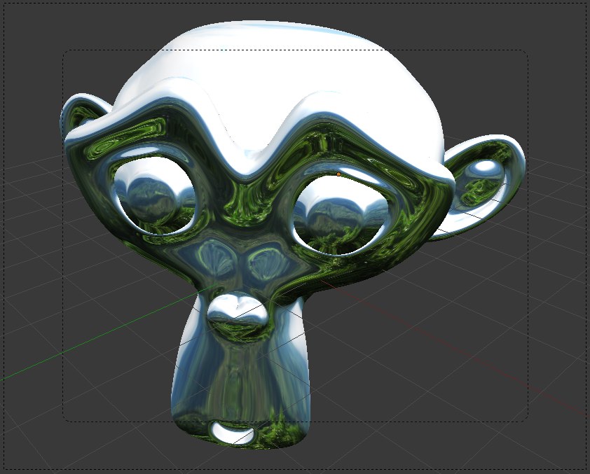
To me it seems you are not using your angular maps as environmental texture, but simply as image affecting the mirror channel of the material?

You method of projection might be simple, but it is wrong, not proven, if the idea is to create an angular map. :wink:
You create some kind of map, that works to an extend. But especially in an animation it is not useable.

For the OP I´d recommend to use my spherical2angular, and simply draw in blender, directly on the spheres texture.

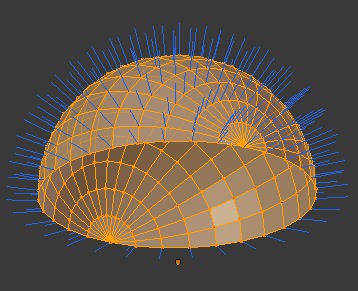
The alternative is to recreate the professional version of a lightprobe, a fisheye lens.

Like this:
http://www.pasteall.org/blend/7365

The IOR/Fresnel most likely is off compared to a real lens, so the distortion might be a tad off, it´s something to play with, but it´s at least close to an angular map. It´s the best and only way to project a planar image to a hemisphere.

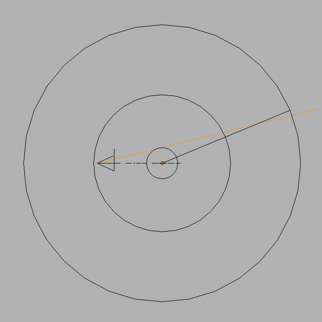
But also this is at best an approximation, if the lens settings where correct, the image would hold no information towards the edges either, because the rays would bend pretty much perpendicular to the camera axis towards the edge of the lens. And there simply is nothing the ray can see.

You are basically mapping the plane to a hemisphere, I am projecting it to a hemisphere, that´s the huge difference. (not sure if those are the correct english terms though)

The huge question is, is the OP making a still or an animation.
A angmap is a useless background IMO. It´s good for reflections and IBL.
I´d simply use a plane (backdrop) or the part of a cylinder if it is an animation without too much relative world movement.

Every raytracer I use (octane, indigo, luxray, thea, vray) is perfectly capable of using spherical maps… highres for background, lowres for IBL.
Just Blender still works with cubemaps for environmental maps (background) and angmaps… well I am not certain what´s a good usage for them at all.

Uhm… NO?
The focus point of a sphere is its center. That´s where all normals point to. So no matter if it´s a 10m sphere or a 1000km sphere the projection is the same.
But try it. Scale the sphere by 1000 and see that there is no difference.

I am nor sure if it´s somehow supported by Blender now to use sphericals. Might be with some hack.
Environment maps support cube maps or planar maps.

Image maps support spherical projections, but… yeh in combination with the “world settings” it seems to mess up badly.
What works is the way I did it, map the spherical map to a sphere.
If you set it shadeless, not affected by light, not casting shadows and wrap it around your scene it works.
You can map image textures spherical, but it doesn´t work correctly with world-textures…
But as mentioned I don´t use it too often, either I use backdrops, or I use a renderer that supports angular maps and proper IBL, not the approximated fake blender does :wink:

@ GodOfBigThings

besides of UV-Mapping there is AFAIK no way to asign one single texture to cover the complete 360° space on a given object.

180° is the max limit, as the textures can be hooked to the visible normals soley, like in this render view:


And here is an other POV to demonstrate these limits:


I guess you have to use two (seamless) 180° material samples instead.
(Or use an external renderer of cause)

Cheers

I find this whole thread most intresting. Seems not many ever gave thought on it…
At some point, when I noticed I can´t use spherical maps with blender I just didn´t care anymore because angular maps are crap. IMO they are a relic of times where it was “impossible” to stitch angular maps to a spherical map on a planar texture.

Perhaps the approximation will get closer to the original if one is using a lens-shaped object instead of an ideal sphere to compensate for the lens-refraction? But I guess this would blow up this thread to some theoretical, time consuming neverland :wink:

The homeland of every scientist :smiley:

Uhm…yes.
I did render before posting. Try enabling texturing on the outer sphere so you can see it’s texture in the viewport.
Then scale it up, and you will see more of it.
Here is a simple explanation. It should also explain why a smaller sphere and an orthographic camera are better. (When using it though it comes out distorted anyway, whether scaled up or not, for some reason)

Note that the ray hits the smaller sphere at a higher angle (measured from the center of it)


P.S. Saw the units in meters in your file. Is that an addon?

This feature comes with Blender:


For you model drawing.:

Even if the orange photon would have a different angle of attack in RL, in the model of Arexma the outer sphere is used as the projection screen and the inner sphere will depict every pixel on the outer screen exactly at the same spot despite the dimensions of the sphere(s).

P.S: This my 10th post. I am not a limited user anymore But where do I get my free dish washer and what are the other privilleges?

P:P.S: And editing a post is now working like a charm.

Umm… so my knowledge is insufficient I guess. To clarify, an image is supposed to be rendered from that file, right? Or is there baking or other stuff involved.
And why do you need to rotate the camera. Assuming this works the way you would shoot a lightprobe in the real world, then this was what I was talking about:

You just press F12 and wait for the render result.
You need to rotate the camera because you create an angular map from a spherical one. The spherical one holds 360° information, the angular can only hold 180°. If you rotate the camera you select the “offset” what 180° of the angular texture you want.
What happens with the “animation” I build in, is that the camera turns 45° further and creates an angular map of the next 180°
So the first angular map shows 0-180° of the spherical map.
The next shows 45 - 225° of the spherical map.
The next shows 90 - 270° of the spherical map.

And if you don´t like those, you can move it freely, for the 180° of the spherical map you like most.

I think the example sketches below illustrate why orto and perspective deliver different results, and why the size of the sphere doesn´t matter.

No dude… you drunk because your optic assumptions are wrong? :wink: :smiley: jk
I fixed your image :smiley:

[REMOVED WRONG FIGURES]

[REMOVED EVEN MORE WRONG EXPLAINATION]

I didn’t know they were supposed to capture only 180 degrees/2(pi) steradians.
What about the gif in my last post?
That was obtained by just a perspective camera only scaling on the outer sphere.

Also, your original setup captures somewhere between 180 degrees and 360 degrees. If you delete half of that outer sphere in front of the camera you get this, which shows that the original setup was capturing more of the outer sphere.

Plus I’m not too sure about the figures you posted in the last post. The colored lines are the surface normals for the spheres.

Incident and reflected rays make equal angles with the surface normal, so if we talk about the ray that just grazes the top suface of the inner sphere, it will go almost undeviated:

In fact, with a perspective camera, you will never see the top of the (inner) sphere.

Welcome Ulf B. As a voluntary gesture, you will receive daily trolling from me and my 198 fake accounts on behalf of the community.