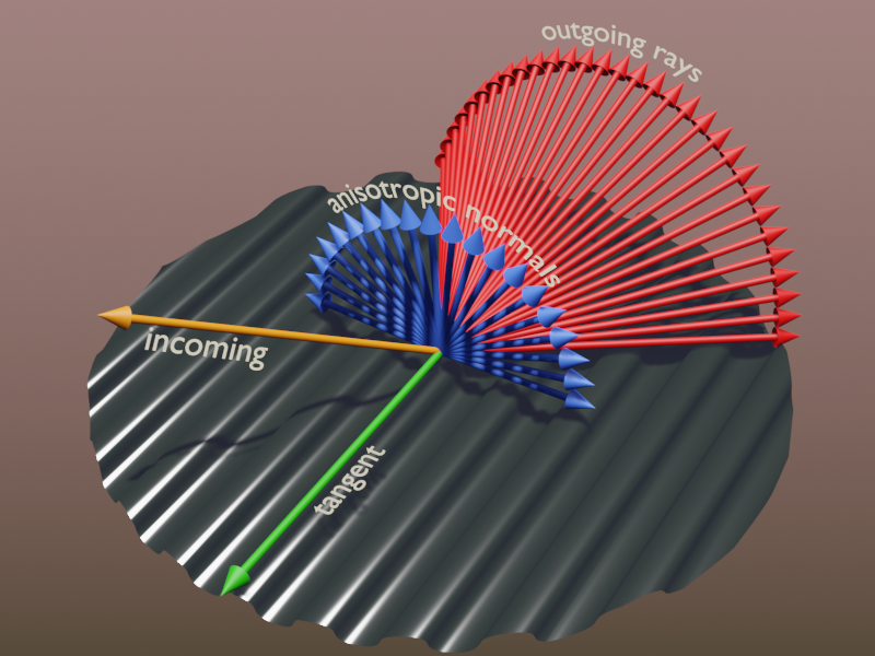
The surface is anisotropic, so there will be plenty Out vectors, and plenty vectors perpendicular to them and the In vector…
Here’s an illustration (not accounting wavelenght interference):
2 Likes
Haha, I’m getting the concept, but my words betray me! Would removing the ‘s’ from ‘vectors’ have been alright?
That’s a really neat illustration. While testing my nodes yesterday, I was actually trying to test how closely I could match the anisotropic shader (plugging the modified normals into a glossy without the colors). The relatively close results got me thinking back to your thread where you mentioned creating a version of the grating shader with the anisotropic node, but I also wasn’t able to produce good results.
I was able to create some nodes for steep parallax mapping with the help of this website: Click!
The .blend file in this link also helped provide the clue to transform the normal and tangent vectors to the camera: Click! I still don’t quite understand this step, but it’s the fix to some odd deformations in the results.
Also, I find UV unwrapping to be very boring, so I made all the calculations procedural! Although, due to the algorithm parallax mapping uses, one needs to enter inside a node group to change the textures.
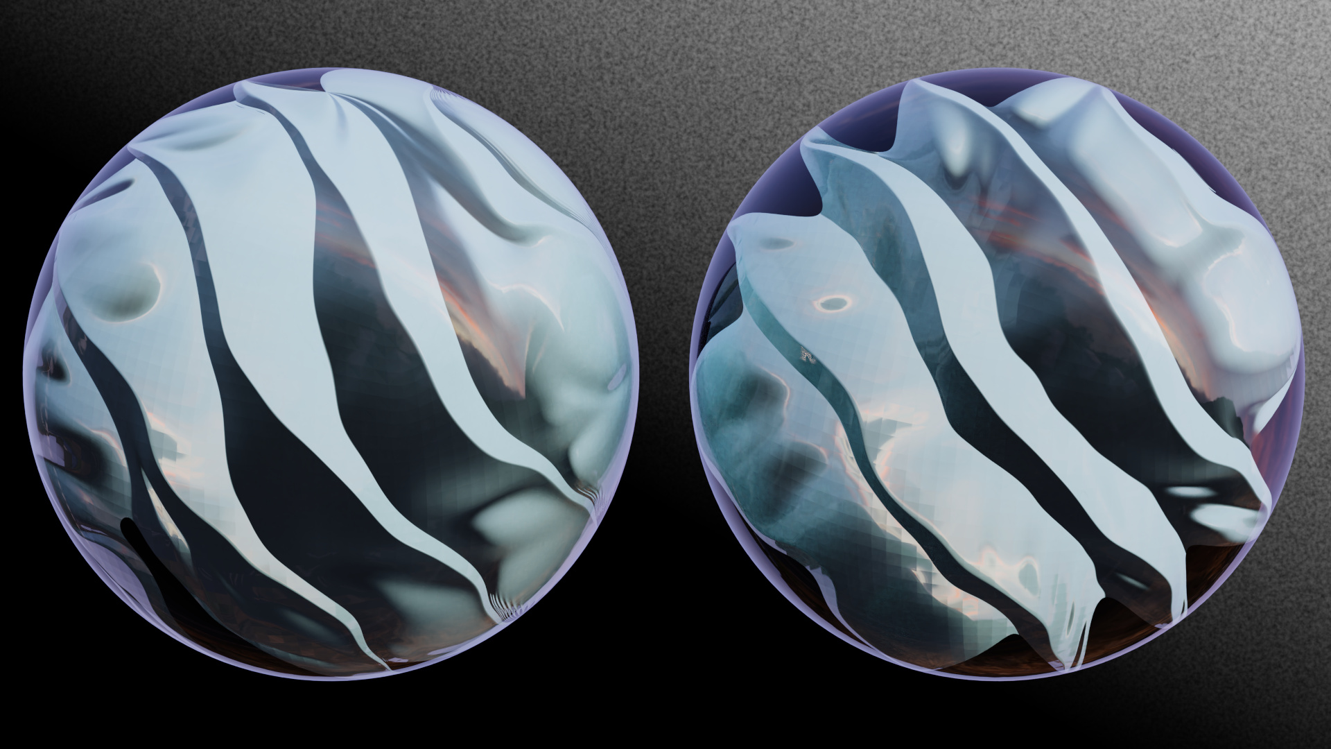
Here are some test renders comparing simple normal mapping (Left) to parallax mapping (Right):


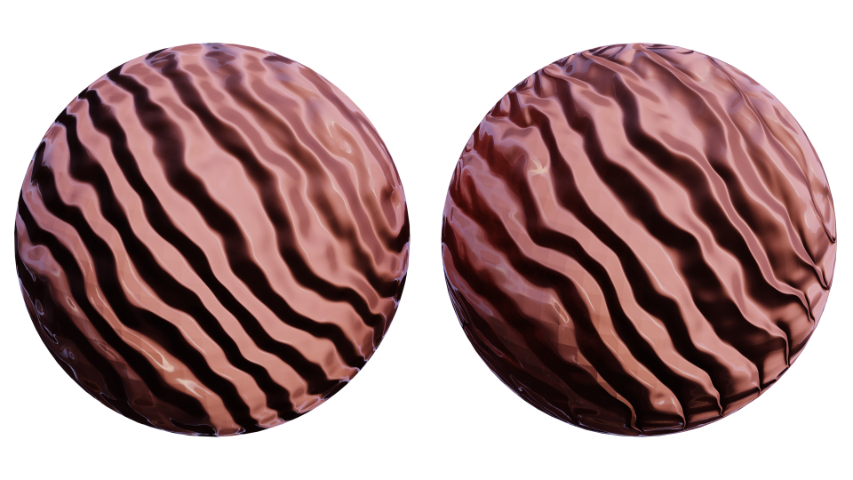
The differences are most evident on flat surfaces, but it seems parallax mapping produces fuller reflections and appear to be better lit. My favorite is the wave texture!
You may have noticed the square pattern on all the surfaces of the spheres, and I think that comes from the low-poly mesh having low-quality normals.
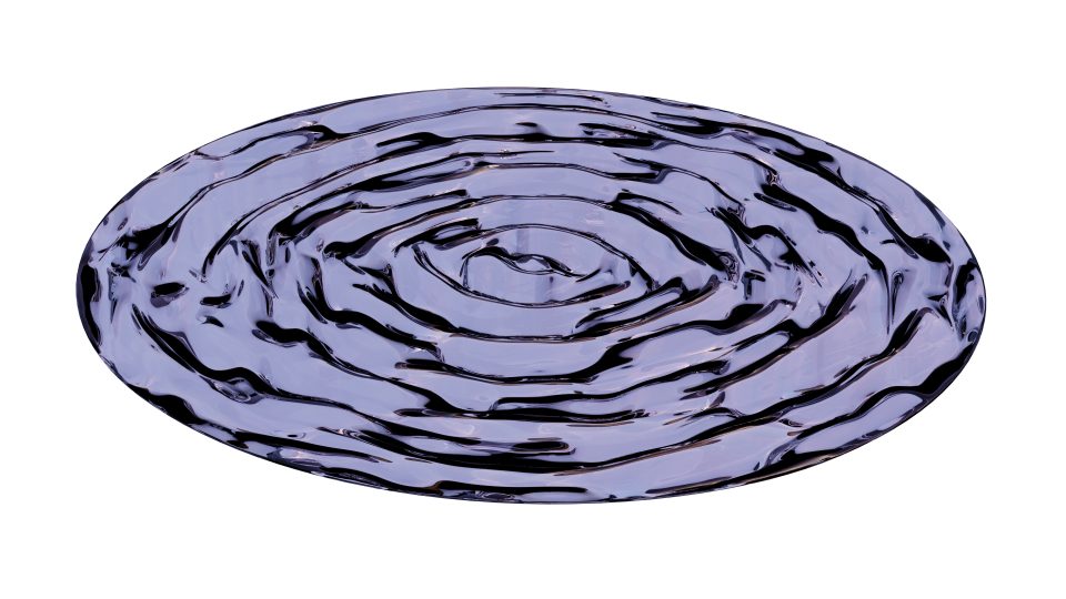
I also tested how it would look on a glass material!
While the results seem pretty nice so far, there are some elements missing I think might really sell the effect. Maybe using the Parallax Occlusion Mapping method in the first link above should come first, because of those pesky stair-step artifacts.
1 Like
I’m having a lot of fun with parallax mapping. I still want to include some self-shadowing effects because the shading currently is only based on the direction of the normals. No shadows are produced by occluding geometry, so trying to simulate relatively deep surfaces looks bad.
At smaller depths, the effects are pretty nice. Curved surfaces show distortion at the edges upon movement, but as long as the depth is controlled, it’s not as evident.
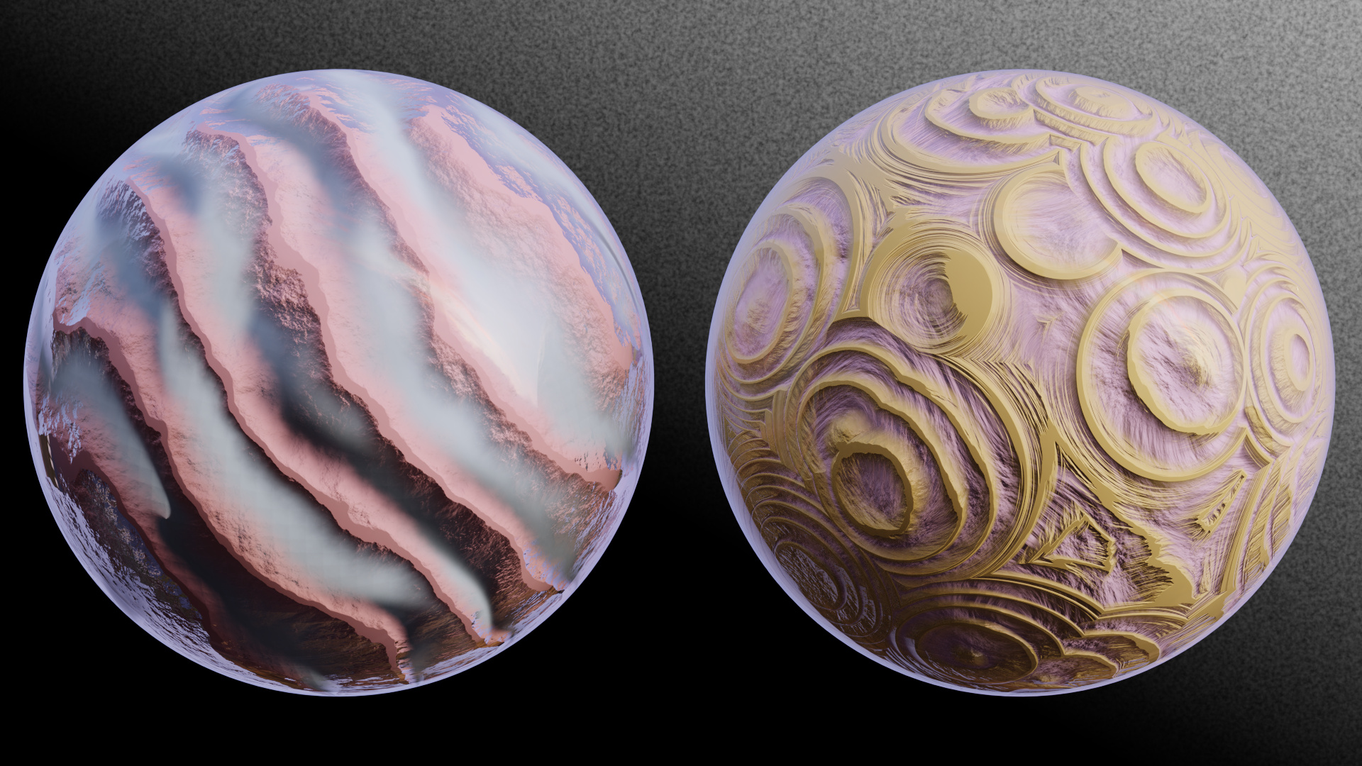
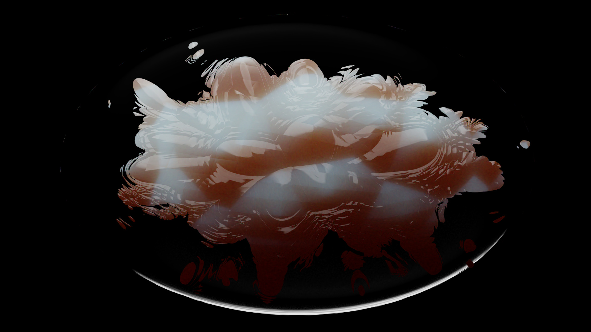
I tried making some materials with volume-like effects to get a feel for the opal material and how it should work. The following layer two different parallax mapped textures each. Some untextured glossy is Fresnel-mixed in to simulate a smooth surface enclosing everything. That effect may not be too visible, and I think it all comes down to lighting the materials well.
2 Likes
I finally figured out how to correct some perspective issues I was getting with procedural parallax mapping. Originally, I tried to mimic UV unwrapped texture coordinates by modifying the Object/Generated coordinates, and it worked! Although, the seams were exacerbated by the parallax calculations, and I just couldn’t let that slide.
After spending hours trying to remove the seams, the idea finally hit me. Imagine the default cube. The top and bottom faces are in the XY-plane, the left and right faces are in the YZ-plane, and the front and back faces are in the XZ-plane. Of course, most texture coordinates we use are based off that geometry. Now, if we have a view vector that we calculated in tangent space, we have a vector in an XY-plane oriented along the geometry of the cube.
That’s the problem. We have texture coordinates we want to modify, but the view vector can only modify them in the XY-plane. How can we fix that? Wait, the vector needs to be in object space! Who knew the fix was so simple?
The many, many sources I’ve found on parallax mapping specifically calculate in tangent space, and I guess it’s because they all assumed a UV unwrapped object where the texture coordinates are only in terms of X and Y.
Here is a comparison of using the view vector in tangent space vs. object space.
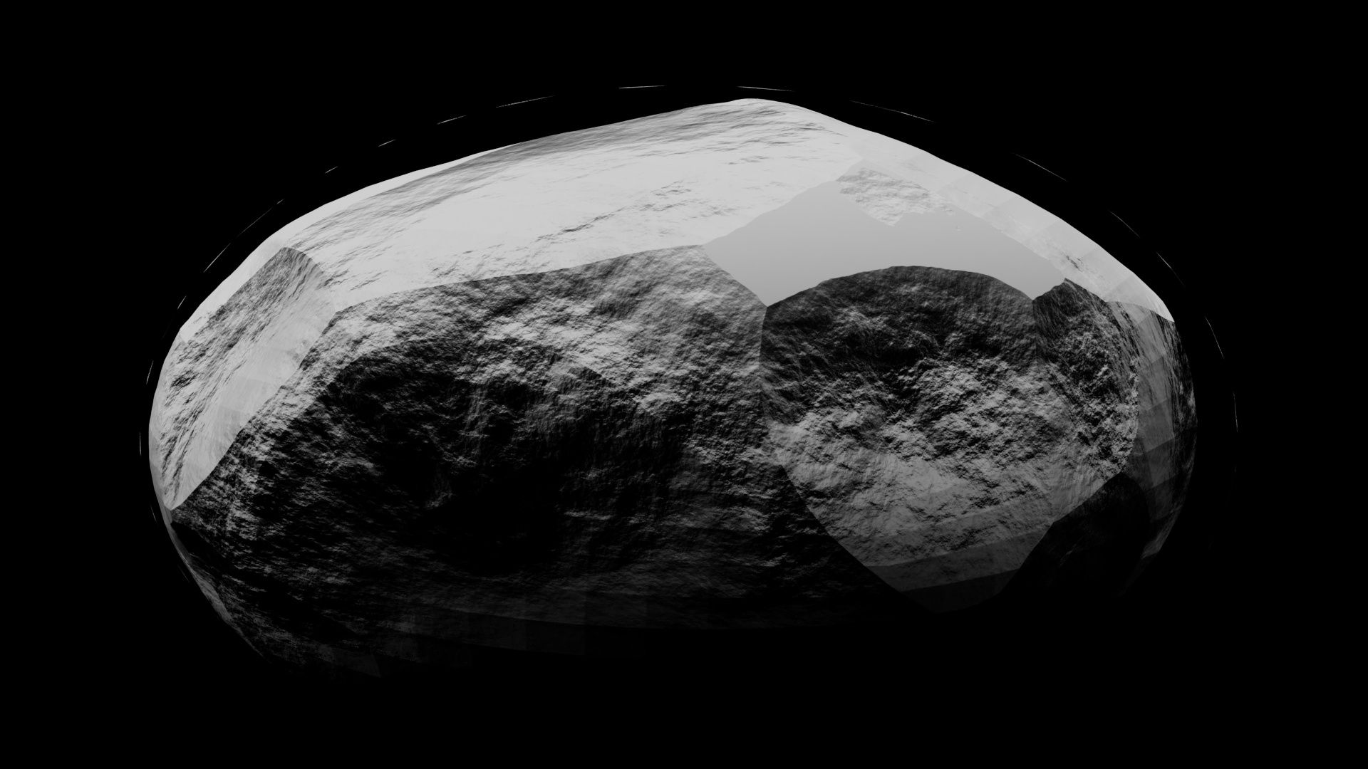
The geometry looks much better after the fix! Oh, and I also figured out how to modify silhouettes, but it only mostly works for spheroids. I’ll need to find another solution, but I thought it would be fun to showcase it for now.
Here, I wanted to push the limits of parallax mapping and the silhouette generation to produce geometry almost completely removed from the original spheroid:
SUB-SEA
I also just liked this texture:
In this one, you can see the remnants of the original geometry. It’s an artifact from the calculations, and I’m not sure it’s possible to get rid of them.
I still need to work on the self-shadowing, but right now, its prospects don’t look too good. The bump map node is very finicky with the number of samples it accepts from the parallax calculations (it usually accepts 15 then maybe 14 after modifying the texture, and even if I revert the texture, it might still accept 14) and I think the overall material will be finicky if I add shadow calculations.
1 Like
I had to fix another problem with the parallax mapping implementation. At large scales and steep angles, the depth map would deform non-linearly. It was difficult to find the solution because many attempts at a fix always produced unexpected results.
Here’s a comparison of the results:
Left: No parallax; Control texture
Middle: Implementation w/ unwanted deformation
Right: Fixed Implementation
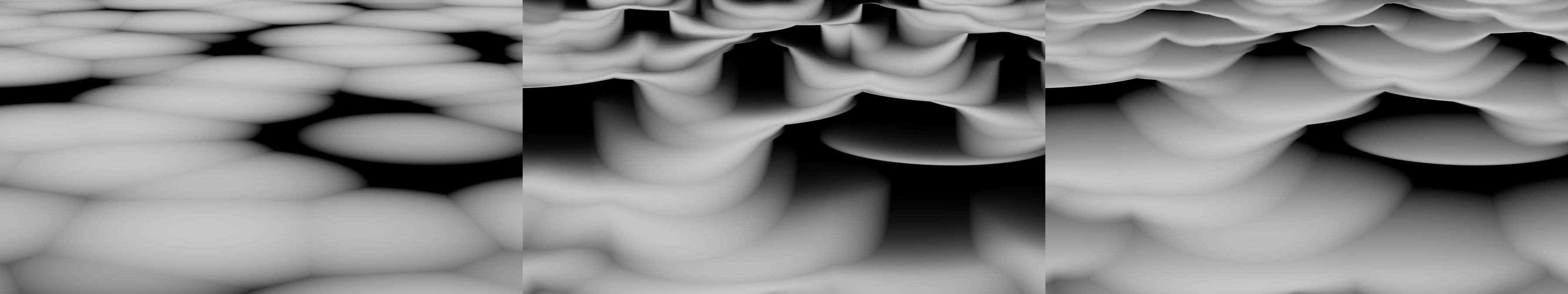
You can see how the deformation caused the loss of sharp, defining features, mainly at the tops of the plateaus. Of course, the problem isn’t completely fixed. If you examine the peaks based on the depth information in the control image, it’s easy to see how some geometry should be occluded.
Unfortunately, I don’t think it’s possible to fix this particular problem without showing artifacts of the limited sample rate.
Left: Correct occlusion
Right: Attempt at correct occlusion with smooth geometry
Even with a small scale, the artifacts still show. At other angles, without the occlusion fix, the parallax still looks good, and I think I’d rather have the smooth geometry.
Really, at this point I’ve been testing an edge case with the ‘large scale + steep angle’, but now it should look okay for most applications, I think.
Hi! I love how this shader looks, it’s the best looking all over the internet!
Can you share both the CD and DVD shaders settings (or .blend files)?
great looking parallax stuff here!
where did you get the parallax maps from?

It’s been a while since I’ve touched Blender, and a lot has changed! And so I was playing around, having fun with the new geometry nodes when suddenly I saw the raycast node! It gave me the idea of making fake refractive caustics for stuff and was surprised to find that very few people have tried it. This was pretty much the only thing I could find: https://www.youtube.com/watch?v=C9iQKsShYIM)
My method raycasts points 3 times: from a fake light source to the object’s surface incident to the light source, from the incident surface to the refracted surface, and finally, from the refracted surface to the environment collection (in the images above that’s just a plane).
It was a lot of fun trying to solve this and familiarizing myself with geometry nodes. In initial tests, I copied the video and used a mesh to simulate the light, but I found I didn’t like how the geometry turned out including all the problems there are when trying to render the resulting surface. The next test I did was placing points directly on the refractive object’s faces which were incident with the direction of the light. This produced results I liked better, but when I tested the case of a surface with an IOR of 1, I saw that the final distribution of points were skewed toward being brighter at the edges of the caustics. This is wrong because light should simply pass through in this case and should keep the same initial distribution, I think. This skew is caused by the curvature of the objects surface. It’s not perpendicular to the light at every point, so an even distribution of point on the surface means a varying distribution of points from the incident light’s perspective.
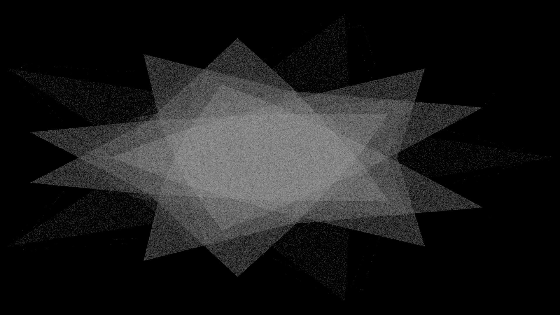
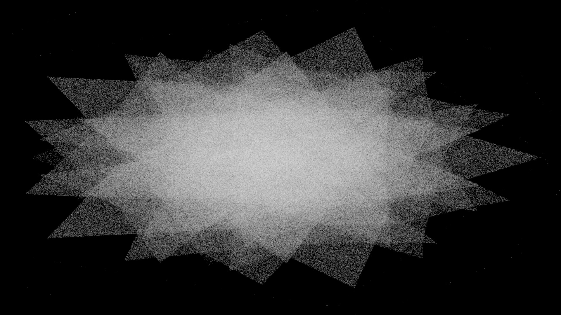
So in my current test, to get an even distribution of light points, I fit a plane to the object’s size and perpendicular to the light direction which acts as the light source. This method is great, but I do think there are still some problems with it. For one, very small points are bad for rendering. The resulting image is very noisy. Another problem is the geometry of the object. We can subdivide and smooth shade all we want, but in the geo node refraction calculations, the surface is still made up of small, flat planes. There is no actual curvature in the calculations. I suspect that this is what causes the hard lines and broken caustic surfaces you see in the images I posted.
Ideally, the final point cloud should be turned into a flat plane which is triangulated with the points as connecting vertices. This should at least smooth out the final render, but I’m not sure that it will solve the curvature problem. Although, from what I can tell, there is no way to do this currently in Blender without an add-on. I did see the ‘Points to Volume’ and ‘Volume to Mesh’ nodes, but after playing around with them, I don’t think they achieve what I’m trying to go for.
Oh, and I have played around with simulating dispersion! Here’s one such test
Anyway, I’m happy to be back, and I hope to share many more fun materials, tests, and art!
Edit: Oh, and I suspect that with the method I use to simulate the caustics, I can adapt it to simulate different kinds of lights! Currently, it uses the simple case of parallel light rays. Oh also, other problems I forgot to mention is that it assumes the object has a backside to hit, and it also assumes that the light travels through the object once.
Some very late responses but
Unfortunately, in the time between then and now, I think I’ve lost the files : ( but maybe I’ll get around to rebuilding it some day.
I actually just made them with the texture nodes in Blender!
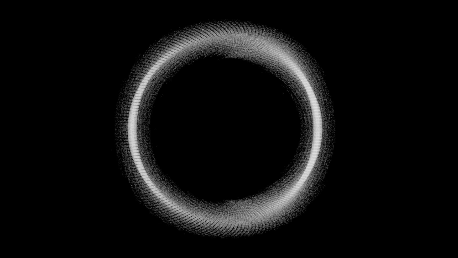
Ahhh, I figured out how to convert the point cloud to simple mesh! The left image shows the wire frame, and the right image shows the caustic material. It’s so cool to see the wire frame, because you can see a parabola was created! This parabola was actually present in the previous tests for Suzanne and a couple of the other objects, but I didn’t realize that’s what it was until now!
The hint to solving how to convert the point cloud to a mesh was in the Fill Curve node documentation. At the very end, it briefly mentions using a point curve to customize the triangulation of a curve that’s being filled! And then the solution hit me. I instance a point curve on every point, find a bounding plane for the caustics, convert that plane to a curve, and then finally use the Fill Curve node.
This is a closeup of the caustics. It’s still not quite where I want it to be, but I think it’s getting there! Currently, the caustics look to be caused by a wavy Suzanne rather than a nicely subdivided Suzanne and are probably better suited for water or something. I actually had to rework the way points are distributed on the initial emitting plane, because the randomness seemed to produce much more waviness. But I wonder if there would be an actual solution to this problem with what we’ve got currently.
Before I forget, here’s my todo list for this project not in any particular order:
- Smooth out the caustics somehow
- Include more awareness of the geometry: Allow for >1 passes and for 0.5 passes : ) through the object
- Simulate another kind(s) of light source. Right now I can only think of light emitted radially from a point, but I’m sure there’s more considering the different kinds of light objects there are in Blender! I just need to understand how they work, I think.
- The solution for converting the point cloud to a mesh only works on completely flat surfaces. I need to find a way to adapt it to work with not-flat surfaces.
- Interaction between different objects that produce caustics???
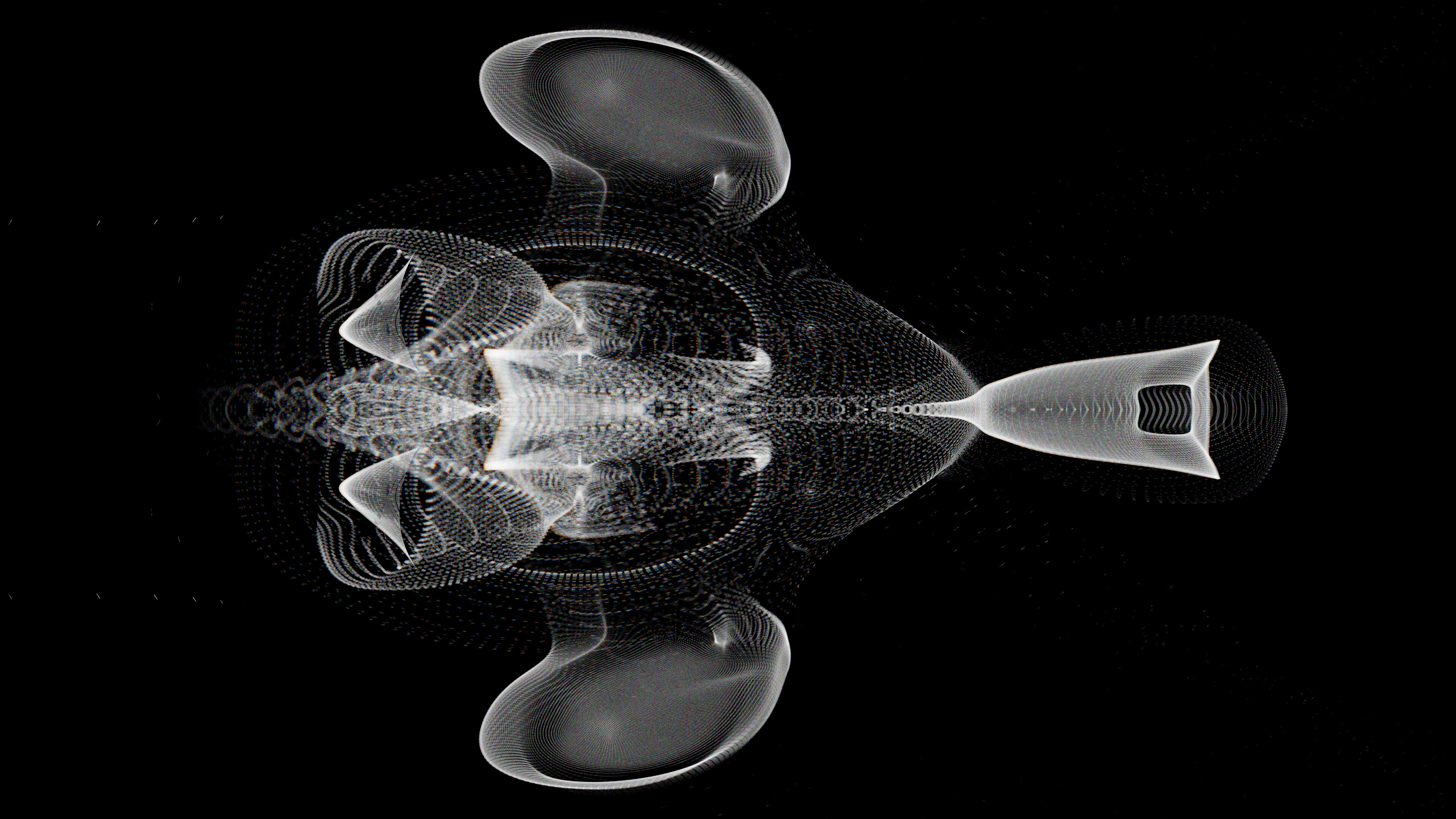
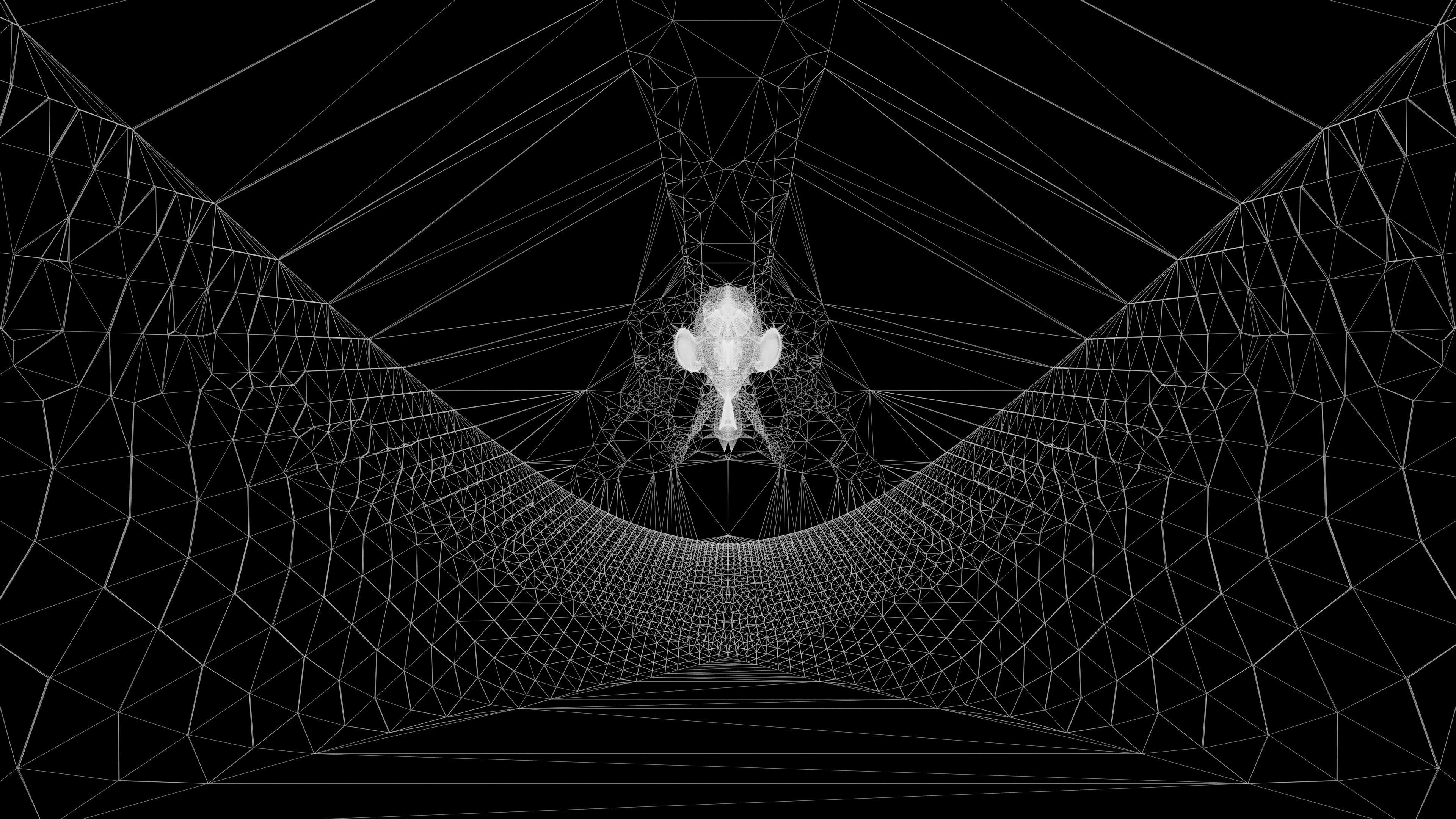
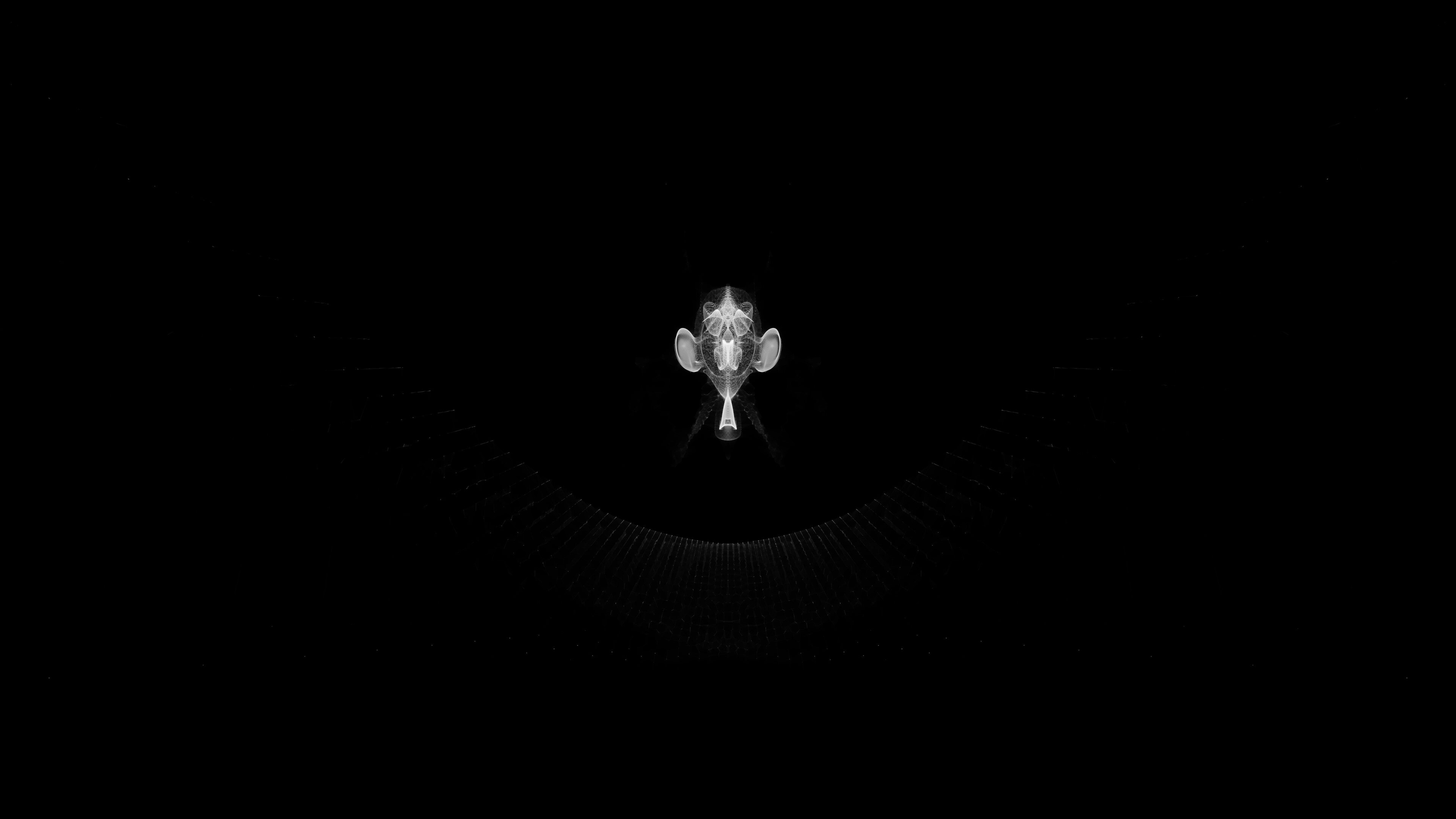
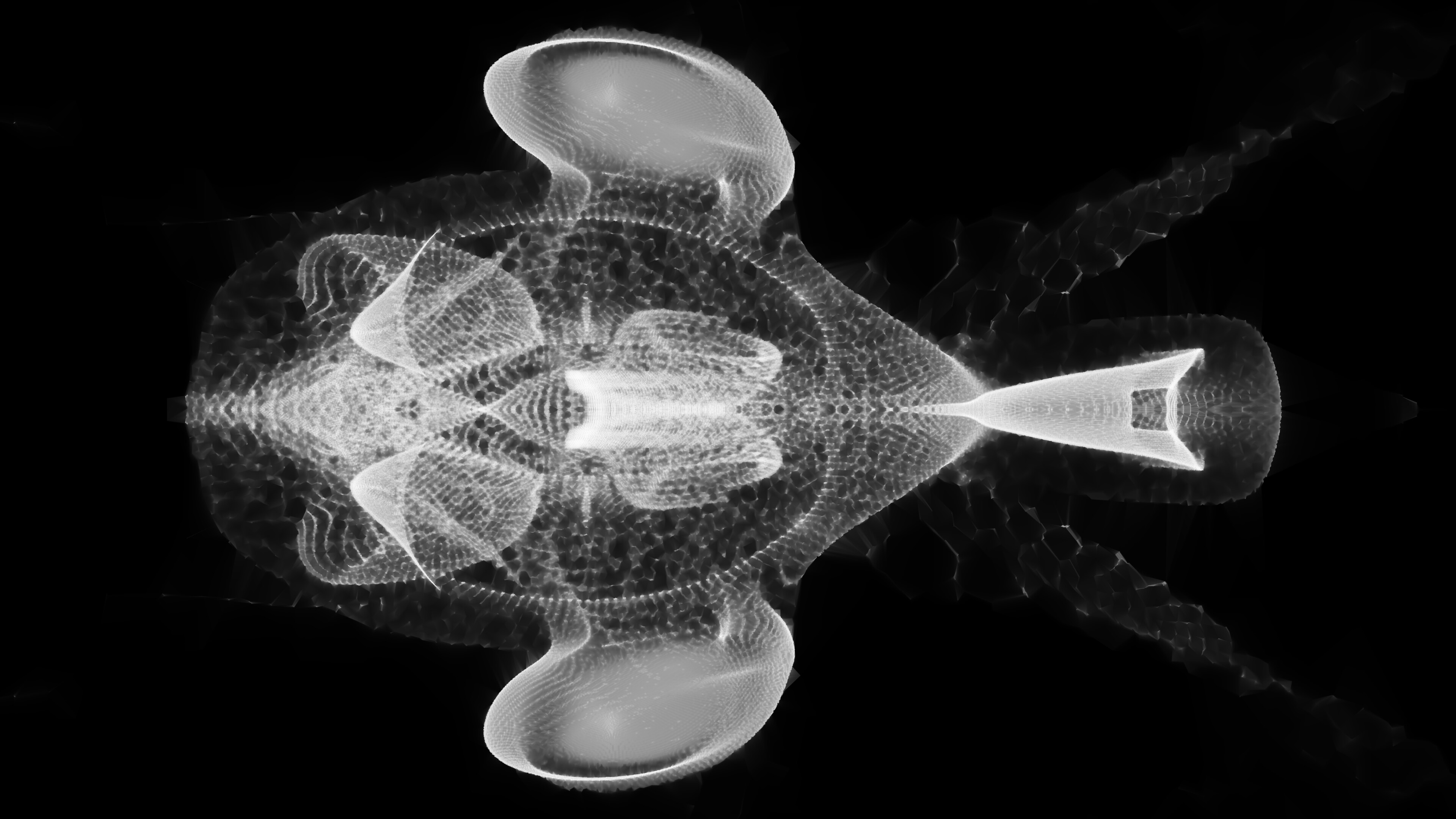
I made a jellyfish animation, and I feel like I’m finally getting into the non-technical side of Blender, haha! It’s been a while since I’ve made something that’s not a showcase for a material or something.
The jellyfish animation also come with a poem, and I’m already cringing at it, hah! Although, I do wish to get better at this kind of stuff, making animations and stories to go along with them.

There are some problems that I do wish to improve with the overall product, but I’m relatively satisfied with it:
- Jellyfish animation doesn’t look natural
- Textures are not consistent (Why won’t you just UV unwrap the thing!!!)
- How to edit mouth clicks (Maybe learn or try better to speak without them)
- Sound effect I chose doesn’t quite feel like it fits my voice
- Intonation isn’t quite the way I want it to be especially at the very end
Here’s a still image:
