here a new shader i build.
freqency multiply value input multiplys the vector fac datas, that are going into the cosine function ,to produce the colors.increase the value for higher freq(default base is 1 for no effect)
thickness input value.usfull values are from 0 to 1 to simulate the color desaturation ,like thicker film would get.
wavelengh input,for color base that are used for the cosine func.
i know, different thickness would give different colors,but i wanted to post this shader at the very basic status.a thickness/color multiplyer for colorshifts could be possible of course.
and rebuilded the basic maths from colorpy code,mainly the reflection and phase function.but i found the usage from the hue node alone for the color is limited.i think the maths into three rgb wave textures coud be better.but im not sure how to split the math for seperate rgb calculation.
edit,so i have to give it up.course for reflecting angle calc ,i need at least a sqrt math function, that isnt in the list atm.
can we make a proposal for missing functions? i have at least two :
the missing sqrt function,and second a cosine wavetex .ciexyz would be uesfull too,if we want to calc with wavelenght.we have a wavelenght to color func.nice would be a color to wavelenght too.
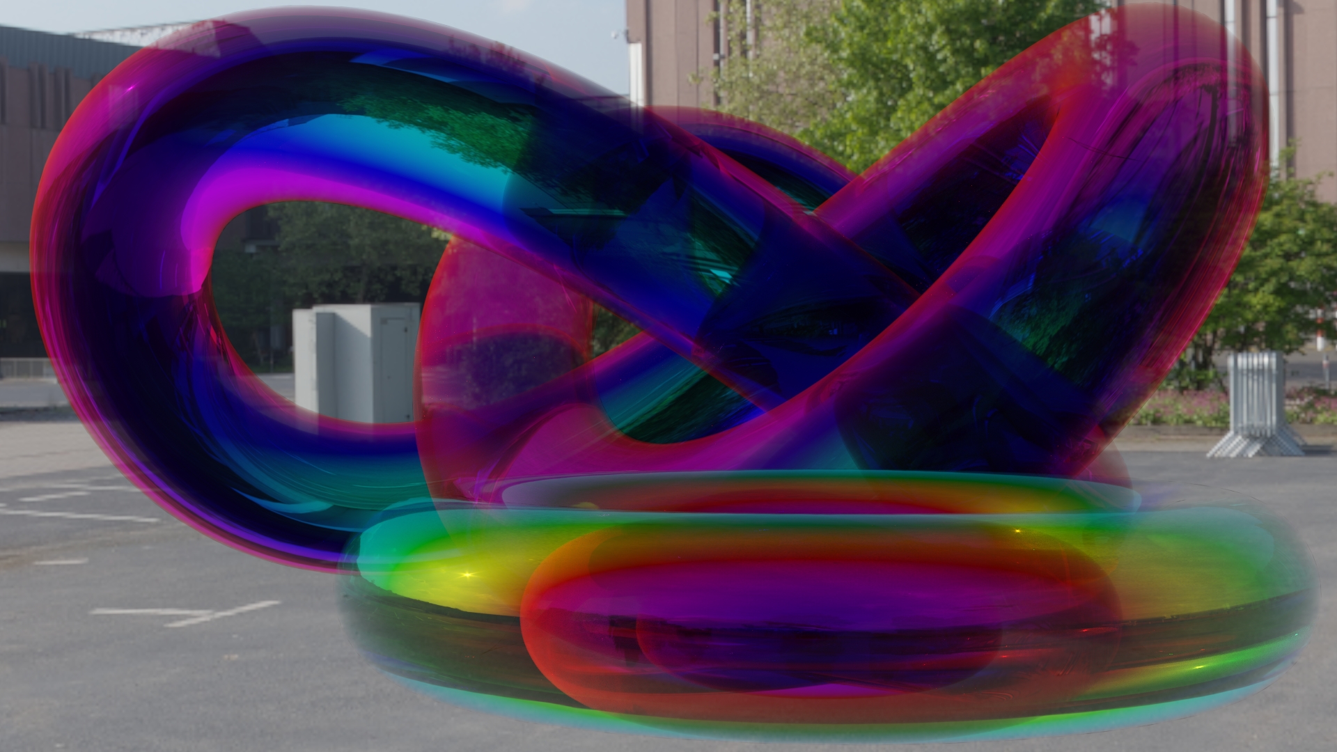
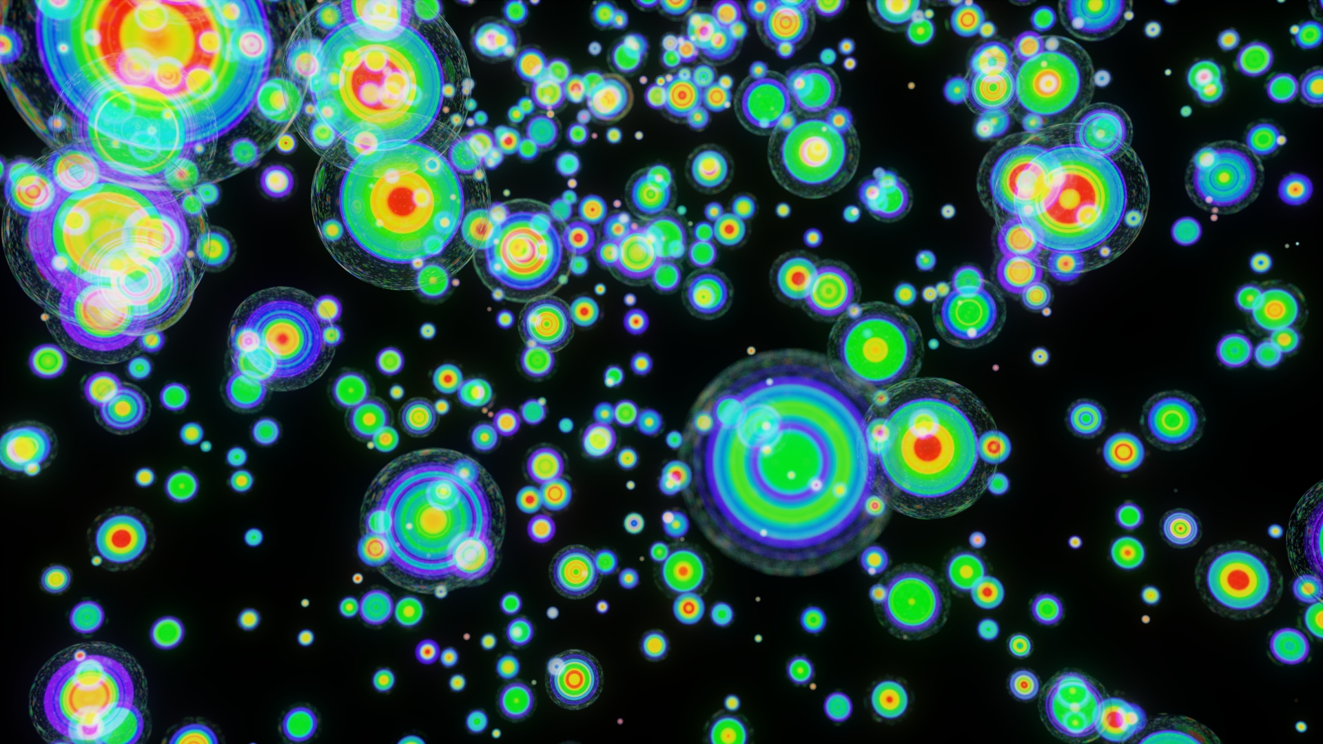
i think this is my best shader so far.good controll over frequency,saturation and base color.from glassy soap bubbles to black colorfull materials are possible to mix are easy.its mostly a artistic shader.
i have seen this video,how to calculate thinfilm thickness.
based on the math from the video,i reversed the math and build a node group, to have the color based on thinfilm thickness as result.
and its working .:yes:
[ATTACH=CONFIG]494169[/ATTACH]
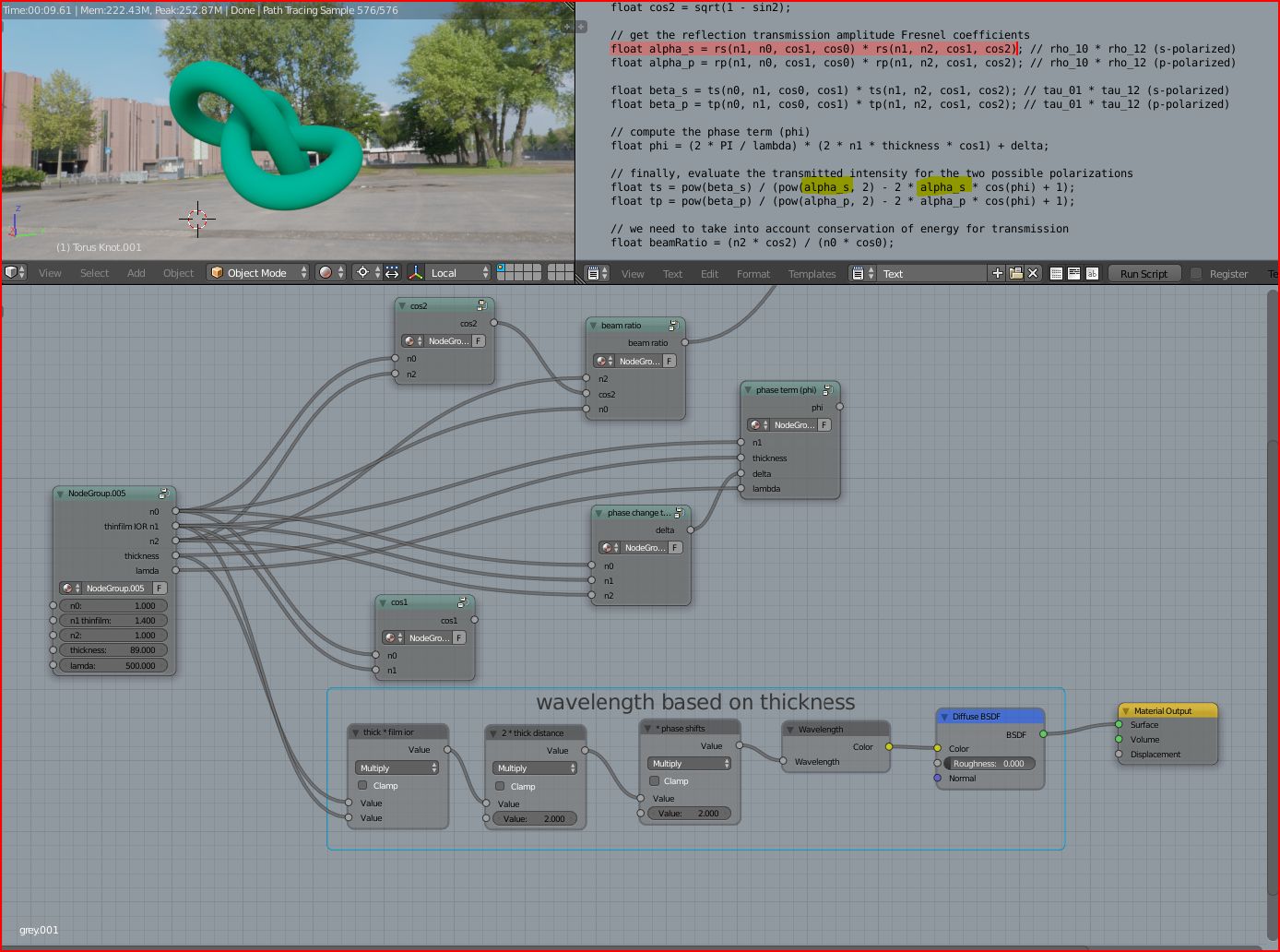
after this,i rebuild the math, from the gamedev thinfilm code.i have build the most parts of the code as nodes,until i came to the red marked codeline.
this code uses four variables at once in one float variable.and i dont know how to rebuild this as nodes.i could multiply all variables seperate,but the problems are at the yellow marked lines,there the code awaits the four variables at once.
its sad ,the code is allmost rebuild but i dont know yet how to overcome this problem.maybe its simple.any advice ?
i saw this video too ,that inspired me to try the code rebuild.i think its possible ,if we can make nodes from math formulas, like this.
oh thanks for interest moony,then i have to repost the picture.every time i want to post,than an error pops up, and i have to refresh the page and login again,what is that?
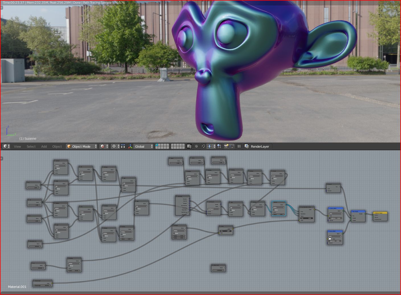
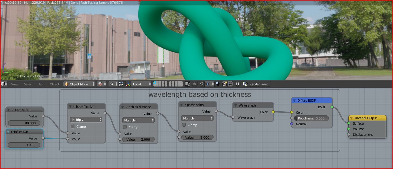
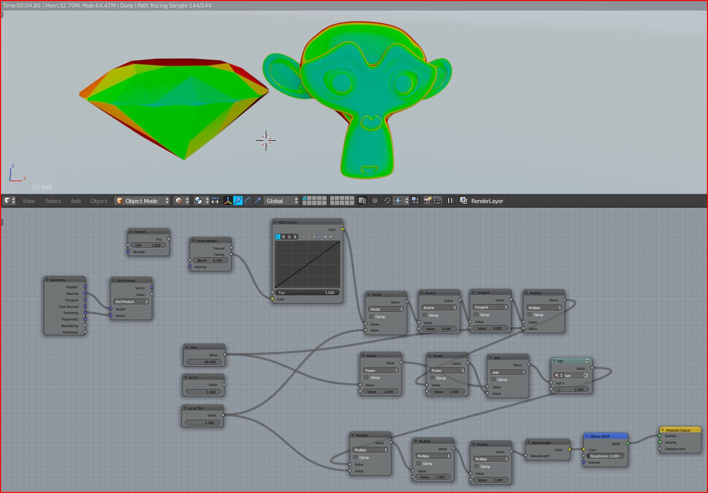
btt.here the missing pic from post #243 and additional i made a pic ,with the rebuild formula alone ,to not confuse someone with the unused notegroups.
and to sum up what i have done.the prof in the video calculated the thickness of the thinfilm,based on the visible 500nm and the IOR from the material.
i inverted the formula,and know it is possible to calculated the visible color based on the given thickness and IOR.
i have put a highmap texture into the thickness input instead of one input value ,and its works too.(with multiply if the map is to dark)
i added the cos1 function to the wavelength code i posted before,and feeded the thickness input with a wavetexture heightmap.
for a better position placement from the texture it would need the full function of the fresnel calculation code,but this is impossible,cause the vector for this needs to calculated first and this gives red node links.maybe there is a solution,i dont know.
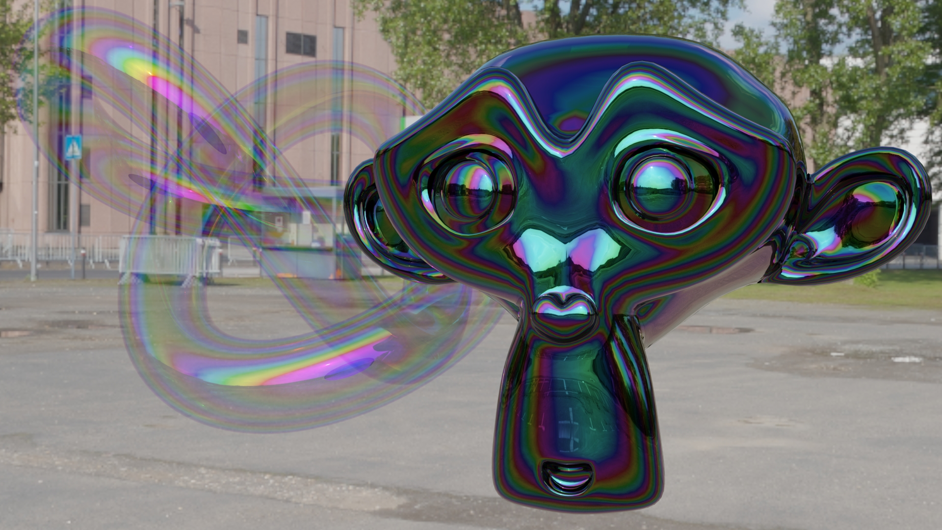
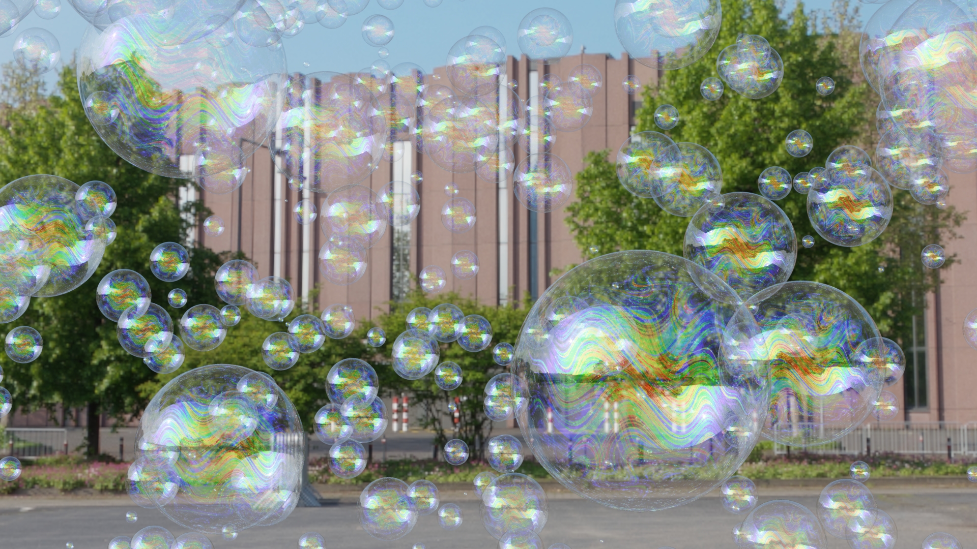
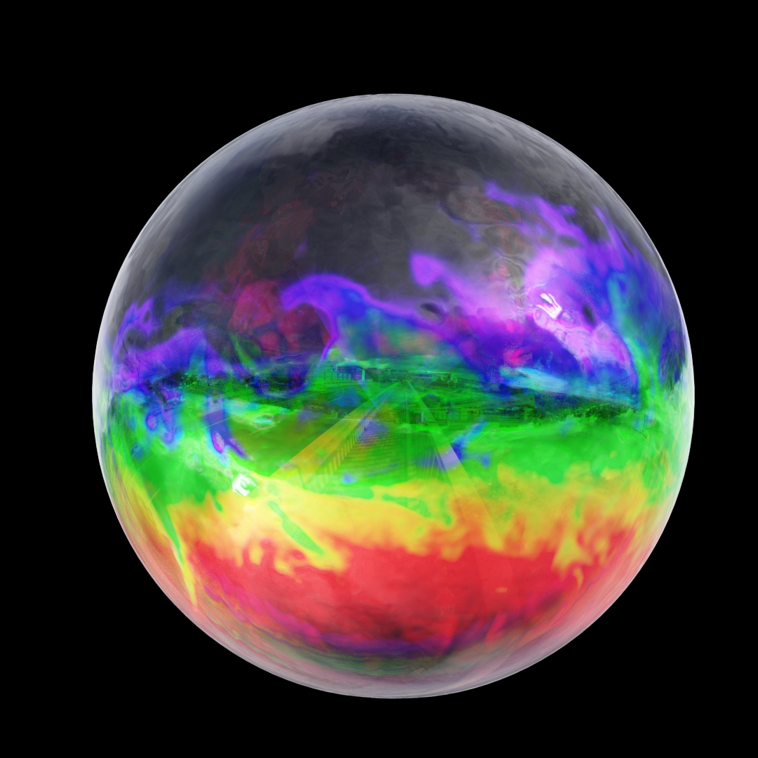
here a render with a hightmap from a soapbubble i found.i unwarped the sphere and the grey heightmap, into the thickness input ,gives the bubbles the colors.the map gives the bubble more and more thickness from the top to the underside ,like the gravity would do to a watersoap(thin at the top and thicker at the downside)(the violet blue is thinner as the red cause the wavelength gets longer with thickness).
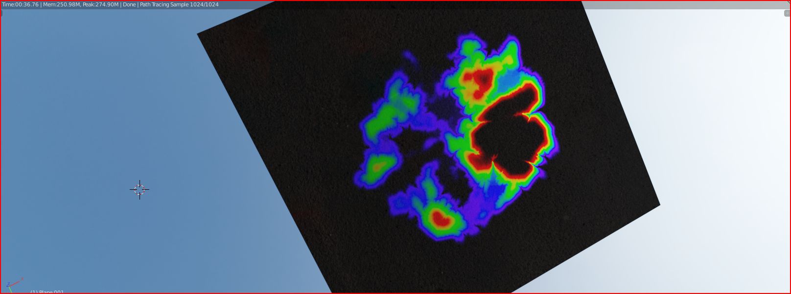
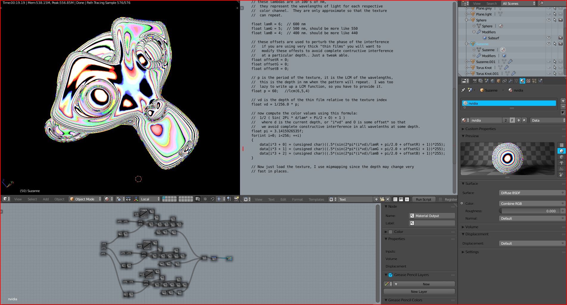
i found this quite simple Nvidia code,and rebuilded it with nodes.it works like the method with the wavtex from moonys shader.it generates separate RGB pattern.with a kind of depth or frequency controll.
i think if i can combine this with the wavelength math.it would be more accurate since this use rgb only ,and maybe getting a simple shader with interference as simple as possible.
Ok guys I’m alway impressed from yours genius, and thanks, for this awesome thread, didn’t understand much but, I downloaded every file shared here. thank very so much.:RocknRoll:
This group node has options for IOR and thickness, turbulence is created by using a texture to control the thickness (and according to the manual for the Arnold Engine, it would be how it works in real life).
Now I’m not all that good when it comes to being able to do fancy trig calculations (as I see in other posts), but the use of color-ramps and other nodes, and the use of techniques such as blending based on arbitrary ranges, have (hopefully) compensated for that.
Also to Pixelgrip, my first impression from your attempt is that the coloring in the bubbles is too bold and too wild to be realistic (the film effect is oftentimes a little more subtle).
@Ace Dragon
of course a real coded shader would be the solution,so untill then we have to play with the possibilitys we have.
btw nice colorramp shader.
the problem for the fake shader are the correct interference and diffraction.moonys wavetex shader is maybe the best artistic shader we can get atm.
since i found this video with the prof,and this quite simple formula,i have tryed to to make a more accurate shader,to reproduce colors based on the given thickness and IORs.the problem is wavelenghts are so small that they are cover the whole object,like your colorramp.and in this cover happens the interference.the best i can try, is to found the simplest method or calculation as possibile to fake this effect, and keep the values as close to the real as i can get.
my last shader test was to simulate different pathlengths (within the thin film) based on view angle.course if you look at a flat angle to the thin film,the wavelenghts gets longer vs the reflect at normal angle in front of you.so the colors are changing to with this.
there are many things to fake.interference,color diffraction,pathlength difference to name a few.
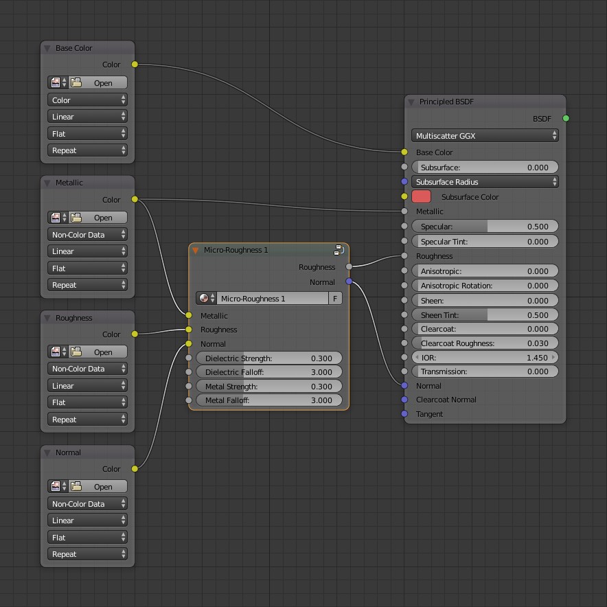
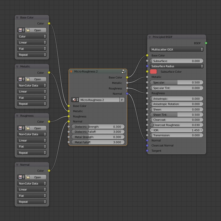
moony, I modified your micro-roughness group to use it with PBR maps.
A Normal Map node is used instead of the Geometry Normal because the group needs to know
the facing direction of the details to generate a correct mask.
Independent dielectric and metal controls. The Metallic map is utilized to enable this feature.
Converted “Softness” to “Strength”. Increase the value to increase the effect.
Two versions are included. The second one has a Metallic output and a Base Color input and output.
This organizes the wires and makes it easy to connect to the Principled shader.
If anyone can suggest other useful test cases - let me know and i’ll create them. Colorpy can handle up to 3 IOR values.
IOR 1 = is the external environment (usually air)
IOR 2 = the thin film (e.g. oil)
IOR 3 = the substrate the film is sitting on (e.g. water)
The ultimate aim of this is to try and get to a node group that will allow me to input a couple of IOR values and a thickness - and the output correspond to these simulated spectra.
One thing I did notice whilst flicking between the various spectra is that the red, green and blue waves seem to lie in the same relative position regardless of thin film and substrate IOR.
Only the overall intensity and overall scale seems to change when changing the thin film IOR (plus there is a phase change when the IOR of the thin film switches from being lower to higher than the substrate).
This observation should hopefully make setting up the nodegroup easier - because once I have the underlying RGB wave offsets and intensities - all I’ll need to do is apply horizontal and vertical scale factors based on the IOR of the the film/substrate and I should therefore be able to recreate any arbitrary thin film.
nice to see your work on your shader goes on moony.
as much i like your shader,i think the biggest problem here is still, how to simulated the interference and the correct fringe scale ,without getting lost in guess working(or make it somehow happen at all).
for one color at one given thickness,your shader could be enough.but this would cover only one color.the more thinner the film is, the bigger and less frequented are the fringes.i have seen a video ,how to calculated the fringes (how many) based on film thickness and film and substrate length on an object.i havent tryed to rebuild this with nodes(since i dont have a interference calc it doesnt make sense).
most of the shader codes im posted before have mostly the basic calculations in it.it is basicly snells law calc for the diffraction in the thinfilm to get the path difference for interference.and as you said the phase shifts needs to be calculated to if the transmitted light hits a different(higher) material IOR.phaseshifts only happen then the next transmitted material has a higher IOR,if the next mat IOR is lower no phaseshift happens.
what i want to say is,for one color the calculation on given thickness is quite simple,but the correct interference ,fringe scale is not,because as i said before,the scaling from the wavelength is so small that blender cant even calc with this small numbers.(ie blender cant even hold, such a small number, in the input value node)
ie 1m/1000=mm =0.001
mm/1000=um=0.000001 (micrometer)
um/1000=nm=0.000000001 (nanometer) for wavelength
to get the idea how small wavelengths are (optical and for calculations)
edit,since we have a wavelength to color node,i could get away with simple calculations and dont needed such small numbers.but for the correct interference scaling dimensions how should this calculated ?
I’m trying to create the shader empirically using multiple data points taken from the figures created using Colorpy.
So far I have determined that the relative sine wave positions remain constant regardless of the IOR of the thin film or substrate.
The only variables are therefore:
A scaling factor for the sine wave length vs film thickness. As the IOR of the film increases - the sine waves are compressed and you get more light and dark fringes across the film thickness axis (in essence you are reducing the wavelength of the sine waves as IOR increases)
A scaling factor for the height of the sine waves vs the difference in IOR between the substrate and the thin film. This one is a bit more complex. If the IOR of the thin film is less than the substrate, the intensity response with increasing thin film IOR is humped. When the thin film IOR is equal to the substrate - the intensity is zero. Then as the thin film IOR increases above the substrate IOR - the response is then linear.
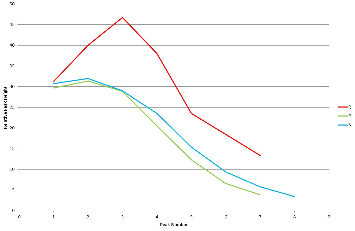
The final complication is that the relative peak heights of the RGB components is not the same. The peaks all start off at the same intensity, but the red component peak intensity increases more rapidly than green or blue. I have tried a function fit to these plots and they are pretty close to a normal gaussian distribution. The red is the worst fit - but that could be due to my method of measuring the peak heights.
if you wonder how the wavetexture is calculated under the hood,here is the code
as you see at line 66,the scale is used as multiply for the point vector and resulting as fac.interesting at line 27 the p vectors for the bands are multiplyed by 10,and at line 30 the p for the rings are multiplyed by 20.at line 38 is the sin function that is used for calculation,if im not wrong.
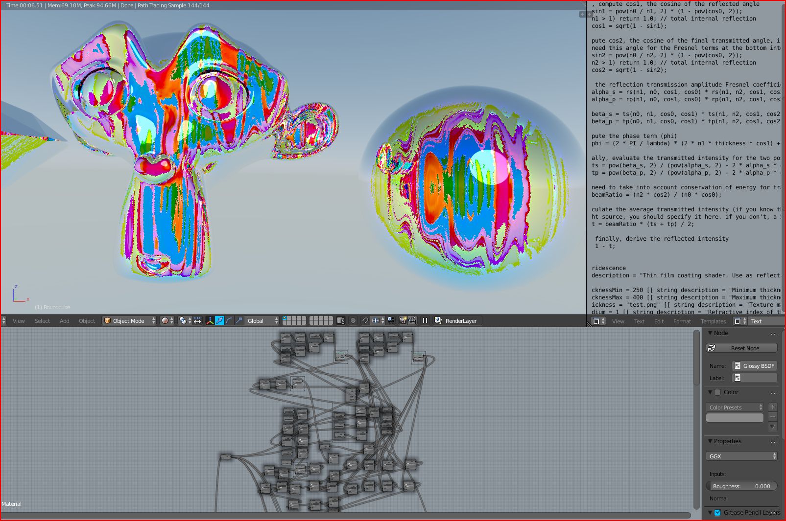
i cant resist and have rebuild the thinfilm code with nodes again.the bad news i did a mistake (i think in the fresnel-polarization math) because in the code ,four fresnel values are calculated at once,and im not sure how to see,how it is calculated.first i added the sum,nothing was rendered,then i set all to multiply and this is the result atm.
the good news is,that no red nodelines happens,and if i found the mistake,the shader could work i guess.its only the codeline with the four values.