i found a interesting paper.and from fig 10 in the paper i replicated the curve from 1 to 0.236.
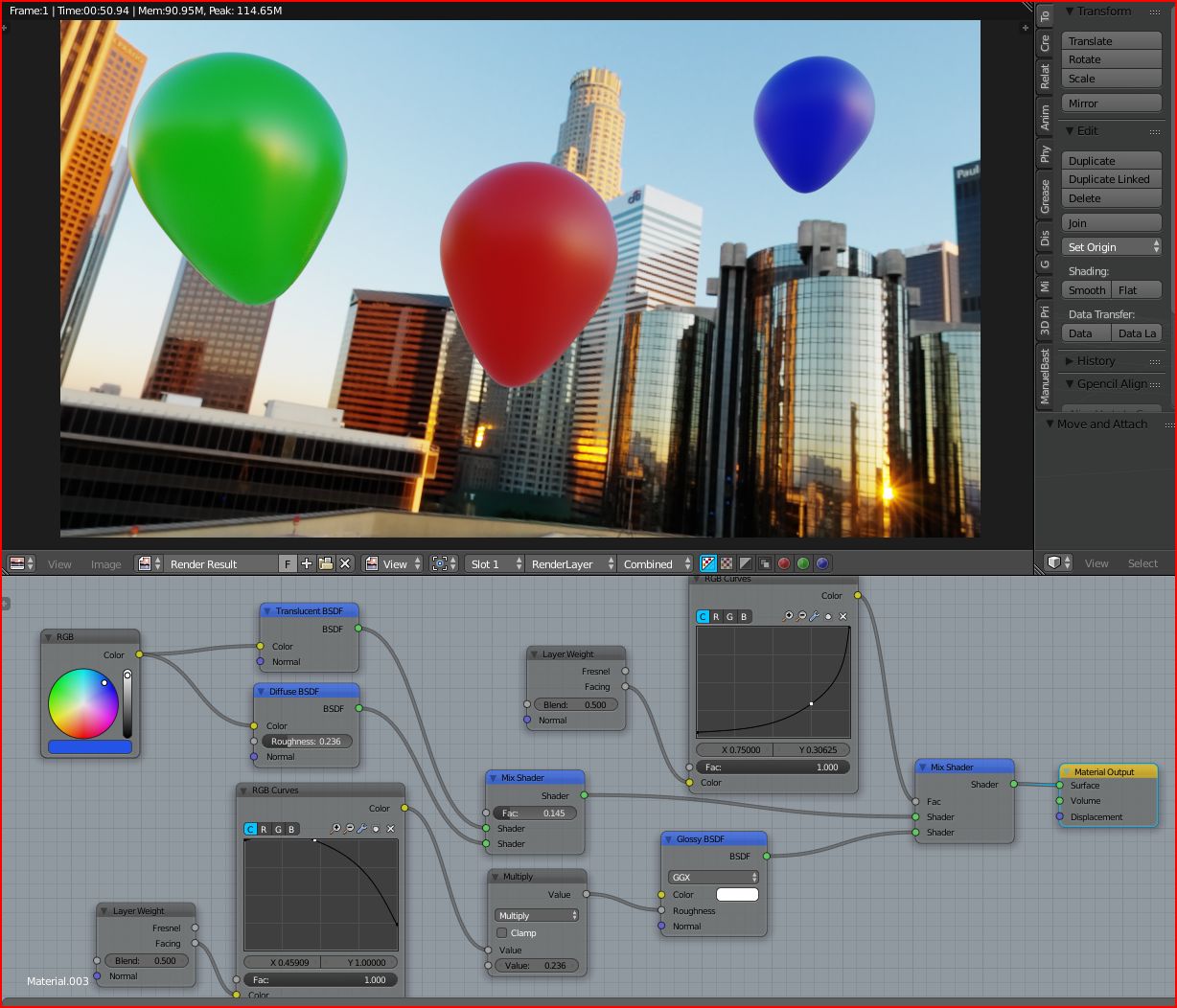
the green balloon with 0.1 roughness.the other two with 0.236
here the paper
i found a interesting paper.and from fig 10 in the paper i replicated the curve from 1 to 0.236.
the green balloon with 0.1 roughness.the other two with 0.236
here the paper
Thanks for the nodes guys. Will this become a feature of princibled shader in blender? Something like angle affect parameter in fstorm I guess
I have suggested as much in the Cycles Disney shader thread - but I dont think there is any motivation to put it in right now.
Both fstorm and thea have variations of this effect implemented - although I think their approaches are different.
Your 0.236 material gives a very similar result to my nodegroup if I use values roughness = 0.25, softness = 0, falloff = 5.
I think my nodegroup has the edge in terms of ease of use though. It’s parameters are easier to tweak and understand compared to modifying RGB curve nodes. The roughness and softness values are identical to the glossy/principled shader values - and the falloff is a simply an exponent that modifies the shape of the falloff curve.
I think the RGB curve is less intuitive to use. There is also a problem with using the RGB curve node with the values you have.
Due to the presence of your point at 0.45909x, 1.0000y, the beginning part of the curve actually humps upwards and gives values above 1. I don’t know whether this is what you intended.
you are right,this was a quick setup from what i recalled from the paper.
here a more correct one.plus the curve from the material matches a ior 1.6, a common value for latex balloon material.
this was just a test with the papervalues.i dont know,if they even usefull at all.but the thing is,if you have any roughness,the value at the 90° dosent have 0 roughness!?.so the curve makes sence somehow.and this is why i rebuild the curve from the paper.
Thank God somebody posted an actual blend file, I tried to recreate Moony’s node group, just stupidly copying the picture and I got something that works in a way that makes no sense to me, like why does a value know how to operate just because you name it ‘Falloff’? I don’t need to know how to make this I just want the micro-roughness node and get to using it, there’s probably quite a few of us that aren’t real good at experimenting with complex node set ups and just want to use them. I think I can use this like the Moony one, just plugged into the Principled roughness, is that right?
Complex :o
Secrop - have a word mate ![]()
haha!
Well… The subject already gets its complexity in real world, it can be even more complex if one is still trying to understand what’s happening in the node editor… ![]()
About the thread topic (to add some more complexity into it ![]() ), one thing that some rough surfaces tend to show at glancing angles is anisotropy. This depends on the micro-structure of the roughness, but balloons show this when filled. In this case, the tangent vector of the anisotropy is parallel to the view vector and perpendicular to the surface normal (cross(N, I) returns such a vector).
), one thing that some rough surfaces tend to show at glancing angles is anisotropy. This depends on the micro-structure of the roughness, but balloons show this when filled. In this case, the tangent vector of the anisotropy is parallel to the view vector and perpendicular to the surface normal (cross(N, I) returns such a vector).
Another point about the balloons (if they are thinwalled), since they are hollow the surface has two different glossy components. One for the outside and one for the inside that suffers from scattering and absortion from the thinwalled surface…
So a bit more math will be required for a good looking balloon! ![]()
Interesting - could you give any examples (images) showing this.
In theory it would be fairly easy to implement - as we could just build an output into the microroughness node which could be used to drive the anisotropy parameter of the anisotropic node (increasing anisotropy as as the view angle decreases)
Sorry for my ignorance, could it help to generate some kind of vector map based on geo (and dependent also on it’s orientation in a world coordinate system) to drive it all (dirt, anisotropy direction, decay, thin film thickness, patina, oxidation…) & would it then be possible to define where materials transitions to another material seamlessly (real smart materials)?
Is there any app out there that generates/simulates such maps?
Substances…? :o yeah, i need to study more.
here’s a small test with a musgrave based displacement:
(render a glossy surface supposed to be our roughness, and record the encoded normal vector from the world, and calculate the histogram)
I had another blend file somewhere with a setup to analyse the glossy closures, but I not finding it…
interesting test,but i dont get it.you make calculation from a displacement map?you say the musgrave gives world vector historigram,ok but vs what ?the viewangle?
materials in realworld have different iso or anisotropic properties.blood for example have a anisotropic around 0.99 a human tissue maybe 0.8 -0.9 or higher if more blood is in it ect.
your example seems to show a structural anisotropy ,like grooves in metal or wood or plastic ect.but not the propertie of material it self has.why the musgrave noise? why this scaleing?
maybe a plot graphic maybe (your measurement vs angle) would be better to understand.
dont get me wrong i like these tests and if we can learn from it,even better
edit,if someone want to test further with balloons,here a interesting link
[http://www.scielo.br/scielo.php?script=sci_arttext&pid=S1679-78252016001402657
https://www.researchgate.net/figure/Imaging-through-scattering-media-with-varying-anisotropy-factor-and-absorption_fig3_308739729](http://www.scielo.br/scielo.php?script=sci_arttext&pid=S1679-78252016001402657)
this is just a quick setup… there isn’t any measure, apart for the amount of samples that get thrown to the world, by hitting some structured surface.
Musgrave was just a quick noise (and I know it is at large a quite anisometric (octogonal))… but the setup can be replaced by any other surface.
The script could automatically save the render, and reload the image; and with different shaders (probably with osl also), some other tests can be performed; We could rig the camera; etc… Feel free to modify it by any means, for any purposes ![]()
edit,if someone want to test further with balloons,here a interesting link
http://www.scielo.br/scielo.php?script=sci_arttext&pid=S1679-78252016001402657https://www.researchgate.net/figure/Imaging-through-scattering-media-with-varying-anisotropy-factor-and-absorption_fig3_308739729
Interesting links.
thanks for clarification Secrop.
i wonder whats the scaling from the roughness is?i mean yes ,its a mix between glossy and roughness.but if you want to reproduce a realworld material,we use our good old fresnel over the diffuse.and its nothing wrong with it.but how rough is a material, is the question all the time.and this it not easy if we thing in three trems (displacement for shape,bump for bumpyness,and roughness for microroughness/glossyness)
sure you can set the roughness to 0.2-0.3 and you have a nice plastic rubber ,but this is only the glossy/roughness for the reflection.
the overall bumpiness and displacement ,what gives the material the “real” roughness to the 3d surface, are most of the time not in focus if someone talk about roughness.
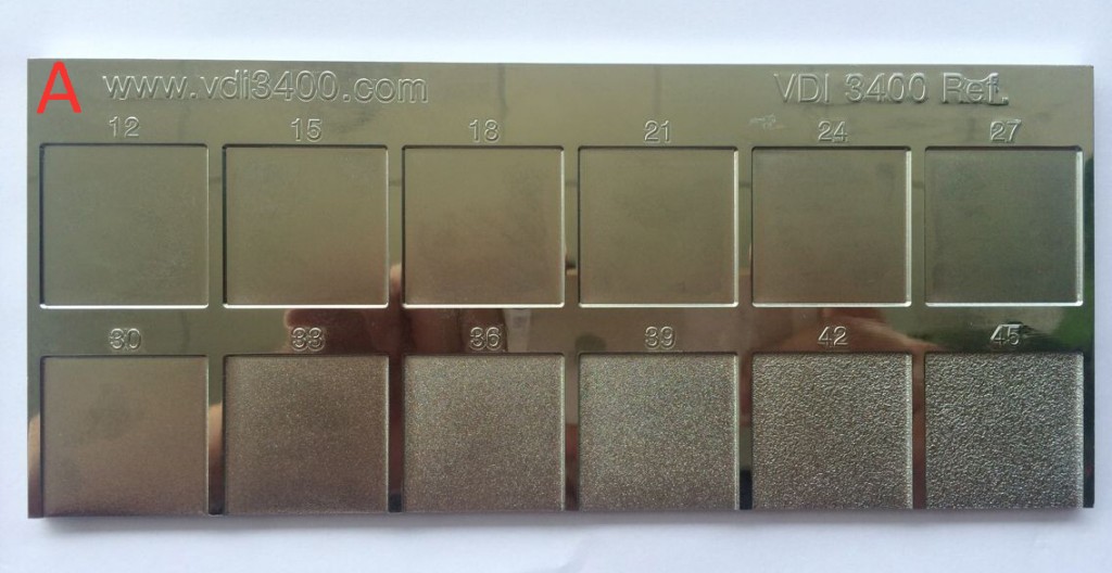
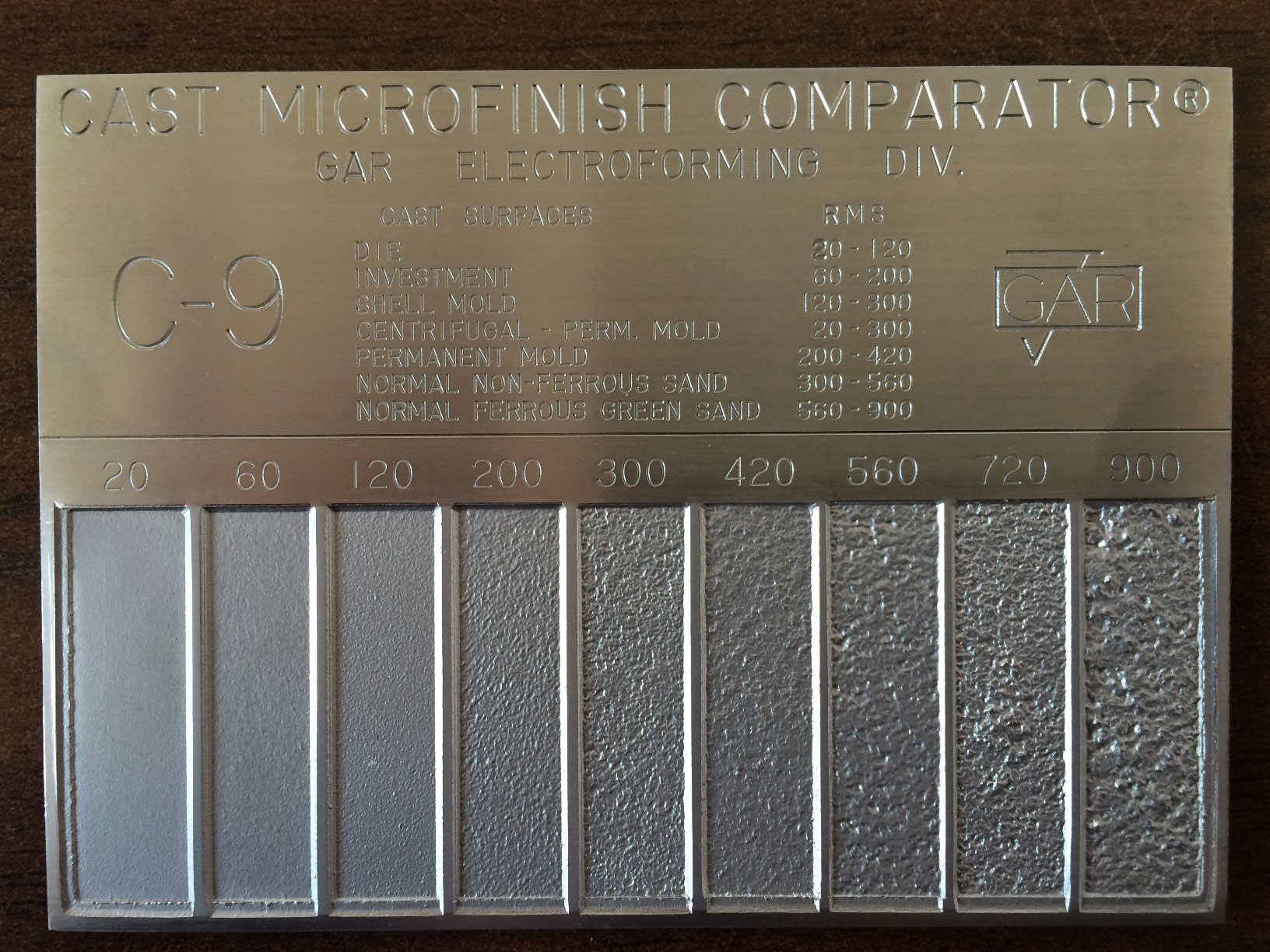
in industrie for automotive for example,there are roughness value charts,which are pretend to have all the same optical or mechanical forms.for example car plastics interior or even the metal at the engine and chassis parts all have production eveness to have the same productionquality.
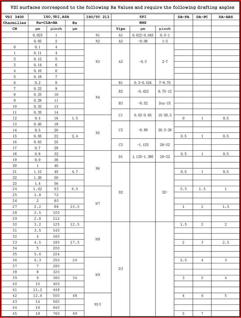
here a industry roughness value chart for optical comparsion.if a value chart for common materials are outthere…it could translated from microroughness to bump to displacement.because the values from the tools are fix Ra values,which can easy calculated.
autodesk allready knows the importance
http://www.vdi3400.com/
here a link to VDI
and a interesting link about gloss
http://citeseerx.ist.psu.edu/viewdoc/download?doi=10.1.1.105.5287&rep=rep1&type=pdf
It’s quite complicated to define the roughness of a material just with some value between 0 and 1. That value just makes sense in the current BSDF equations, and it’s by far a good representative of real roughness. The roughness there has no structure (apart for some anisotropy direction and scale), and the value used is just a reference of how much variation from the sample normal some microfacet can have. It’s use is completly statistical, and the output is very uniform. You cannot do things like this just from the roughness value in Cycles! In this sense, the only option we have for doing other than sanded roughness, is to stack multiple different aniso/glossy shaders, until the distribution result gets near the real world one.
The second part of the problem (I don’t know how many times I’ve referenced this here), Fresnel is not computed based on roughness (which means using the micronormals, thought we don’t have access to the micronormals of any closure at the fresnel node). Any use of fresnel with rough surfaces will not be correct, which ends up in: Eyeballing, eyeballing and eyeballing.
Saw something interesting today - which makes me wonder whether the solution implemented in the Principled shader to deal with Fresnel halo at high roughness values is incorrect.
Balloons again - but this time in a shop.
They weren’t the shiny type. They were very dark grey/black in colour and had an almost powder looking surface (by design as far as I can tell)
At glancing angles however they didn’t exhibit the microroughness effect like I observed in my own balloon - but rather they exhibited a very strong fresnel halo like you get if you mix a dark diffuse with a high roughness light glossy using fresnel (see image - this is almost exactly like what the balloons looked like).
I always thought the fresnel halo effect was an undesirable artifact of the renderer, but it appears it may actually be a real phenomenon that is visible in some real world materials.
Trying to replicate this effect using principled is almost impossible - since the fresnel term has been ‘corrected for’ and reduces in intensity as the roughness increases.
edit - you can kinda get this effect by boosting both the specular, sheen, clearcoat and clearcoat roughness values right up to their maximum on the principled shader - but i’d say the effect is still a little more subtle than I observed.
to my eye those show same glossy surface at gracing angle as the standard ones
(hi-res to observe better)
No - those balloons look like my pink one in terms of reflections.
I studied the balloons in the shop for several minutes from various angles whilst waiting to be served and they showed no sign of grazing angle glossy reflection.
I have been studying materials a lot over the past few weeks and this is the first instance I have found which doesnt show even a tiny bit of grazing angle glossy reflection.
next time buy one,or make foto with your smartphone