Oh, approximation of Schlick’s approximation ![]()
Not sure if it is still usefull, but here a test.
Node setup:

On the left , it’s not connected, on the right it is.
Scene setup:

You see the rotation point of the camera (around the 3d cursor)
Will post some pictures of real life , similar setup in next post.
Not sure what conclusions to make out of this yet.
Have you tested the node group in post #51?
Here the real-life pics:
1)

Facing angle (well, more like 40 degrees)

Grazing angle
Made it in the kitchen.
Who are you asking? If you ask me… I was planning to make some other tests (later this week), some comparisson with nodegroups provided here.
This first test was to get an impression of how the principled shader behaves and a simple micro roughness.
i think its has fresnel for sure,but for the last top material we want to simulate.for example if you want a car paint finish,the top layer is the clear coat,and for this we need the clear coat fresnel.
i also have experimented with roughness values a few months ago and have bookmarked a few links i found interesting
some have math in it,maybe useful.most papers talking in um thats micromilimeter. 1/1000 mm
here the links for interest
https://www.finishing.com/307/63.shtml
http://www.finetubes.de/produkte/technische-referenzen/oberflaechenbearbeitung/
http://www.innorat.ch/RA-Werte_u2_71.html
Yes it has Fresnel - but you need to be careful not to conflate two different effects.
Fresnel increases the brightness of reflections at glancing angles (and conversely reduces the reflection at facing angles). The effect is especially prominent on glossy materials (like clear coat) - but can be observed even on rougher materials.
Micro-roughness increases the sharpness of reflections at glancing angles - and is especially prominent on matte plastics, brushed metals, satin paint etc.
A real world material should include both effects - as the node setup in post #51 does - this means that reflections become both brighter and sharper at glancing angles.
Using micro-roughness alone doesn’t work as the reflections will stay the same brightness at all angles.
Including the Fresnel term alone doesn’t work as reflection stay the same roughness at glancing angles, resulting in Fresnel halo.
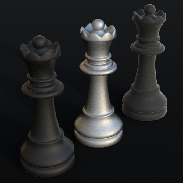
This image shows the same material with the same roughness (a black rubber material). The closest chess piece has both Fresnel and micro-roughness effects active, The middle one has micro-roughness only, with no Fresnel and the furthest one has Fresnel only with no micro-roughness.
i know what you means,but every material has they own fresnel anyway,i think thats important to keep that in the math.its the diffraction and falloff we want to find out the best way.
here one fresh link ,i think a very interesting paper
i think chapter 3.2 -3.3 has the answer with the math (optical path lenght OPD) for the diffraction effect
Well - yes if we are going to treat it perfectly accurately, then each face of the micro surface would have it’s own Fresnel term based on the angle it presents relative to the viewer. But then again - if we are going down that route - then surely the micro-surface itself should be modeled using geometry (just as it would be in reality)
Unfortunately - in our treatment we have no information about the micro surface structure.
- Is it rough and made up of sharp flat sided micro-facets or is it made up of smooth bumps.
- Are the tops of the bumps sharp, or have they been skimmed flat.
- Are the surface features taller than they are wide, or wider than they are tall.
- Are they oriented in a certain direction or are they oriented completely at random.
- Are they all the same size - or do we have a mixture of surface features that are very different in scale.
I couldn’t tell you which of these best describes the actual micro surface on the back on my I-phone case or the surface of my plastic tape measure - but what I can do is eyeball a set of parameters based on the node group posted earlier that gets me pretty close.
On one of the material examples, has anyone actually offered a photo to back up such claims as micro-roughness on rubber (especially in cases like used car tires)?
Those are pretty rough materials to begin with, and I have not seen renders from years past where such objects had a tendency to produce halos (one reason why I think that a decent chunk of the problem is due to the fresnal node not giving a usable result for opaque objects at all by itself). The halo issue in visuals from commercial software didn’t even seem to become a major issue until the PBR craze regarding realtime graphics hit (though part of that may just be a matter of whether there’s a proper reflection probe setup).
Can I add an additional question.
Can micro-roughness, or a micro-surface cause colored specular reflections? (Caused by the bounces in the ridges/grooves, where the specular reflections reflecting light towards the color of the surface).
i’d imagine roughness can be treated similar to all Substance/Matter basic property:
Homogeneous: simple, approximated curve or line falloff between min/max roughness
VS
Heterogeneous: complex curve + multilayered map ~ wavy (as frequency) or even split (RGB) curve falloff between min/max roughness
I assume then, If going for complex reality effect, iridescence must be taken into account also.

That’s not a bad idea at all.
In theory yes we should - however iridescence is very hard to achieve in Cycles given cycles isn’t a spectral renderer.
Secrop did some work on iridescence a while back - and his node group was incredibly complex.
Including such effects at this stage is probably wildly out of scope.
Inspired by MartinZ’s wave test - I have created my own scene to try out different surface shapes and sizes. Images are blurred intentionally as I was getting some moire patters. I used the inbuilt wave texture and micro-displacement to create the geometry. I used an RGB curve node to modify the surface shape and a math node to change the height.
These are the surface types I have tested so far:
- A sine wave
- Flattened sine wave (same height as 1)
- Sharpened sine wave (same height as 1)
- Sine wave 1/5th the height of 1
- Sine wave double the height of 1

It’s pretty clear that both height and shape have a huge impact on both the falloff characteristics as well as the facing and glancing colours.
I suppose the next stage would be to formalise this scene. If I can measure the angle of incidence at various points on the planes - I could then plot the red colour value against angle on a graph and get a set of measured falloff curves for each surface type.


Moony can you share that scene to make comparison tests?
Here is a quick and dirty set of falloff curves based on the above images (don’t worry too much over the wobbly bits at the start of the blue/purple curves - these are likely due to measurement error).
The x-axis is not angle, but it’s related to angle. I added a black to white colour ramp to the planes - keying off the Layerweight node facing value and rendered an image. I measured the grey scale value on this reference image against the red value from the 5 images above at various points and plotted them against each other.
