Hi everybody,
I’m trying to match this milky glass material, but going crazy to get it right. Have somebody an idea how to improve the shader?
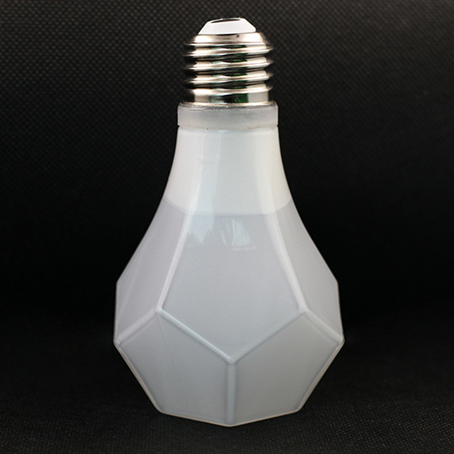
Original photograph:
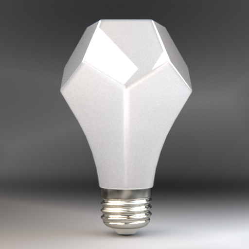
Actual WIP render:
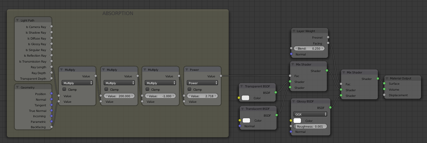
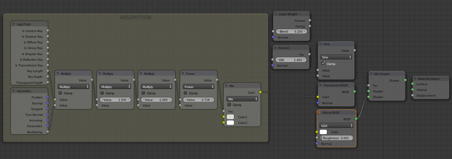
Shader setup:
Thanks in advance.
Eugene
Hi everybody,
I’m trying to match this milky glass material, but going crazy to get it right. Have somebody an idea how to improve the shader?
Original photograph:
Thanks in advance.
Eugene
Can you explain what you are trying to achieve using the various parts of your node setup. In particular
Why are you feeding the ray length and back facing nodes into the “absorbtion” part of your node setup.
Why are you mixing the fresnel and layer weight via a sine math node and using this to control the glossy/translucent mix?
It’s difficult to explain. Please watch this Absorption Tutorial on “BlenderDiplom” or this one on “CGCookie”. This tutorials explain the setup clearly.
It is just one of different approaches to get the right fresnel falloff between the translucent and glossy shader. I could use the ColorRamp Node after the Layer Weight Node, instead of this constellation. But it looks not bad that way.
You might want to use the wireframe modifier to make the grid work more pronounced.
With the wireframe modifier you can see all the edges additionally to the surface. This is not what I’m looking for. But maybe I’m wrong. Can you explain your approach more clearly, please?
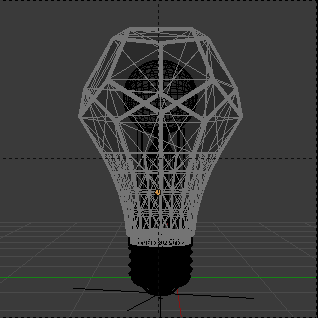
Mesh:
Yep - I have seen that tutorial. The problem is - in your setup, it appears to doing very little, just changing the colour of the translucent ever so slightly. I would have thought you’d actually want to control the level of translucency based on depth - not just the colour of the translucency.
You could try using that approach - but use it as a mixing factor between transparent and translucent shader - rather than affecting the colour of the translucent. Alternatively - have you tried using the volume shader nodes. That tutorial was written as a workaround before volumetrics were implemented.
As for the falloff between translucent and glossy - i’m not sure your node setup is having any effect. I have just rendered a sphere mixing glossy and diffuse both with your Fresnel/Sine mix setup and using the Fresnel node straight - and cannot see any difference even when flipping between the two images.
The object you are trying to emulate appears to have a white plastic cage overlayed with (or inlaid into) the translucent plastic. In order to properly replicate this in your scene - you would be best off trying to actually build the model as physically accurate as possible.
In your model - it looks like you have modelled only the outside surface of the object (although it is hard to see from the wireframe supplied).
The Trignometric functions of the Math node, only use the first input. (So are the ‘Round’ and the ‘Absolute’ functions). The second input will be discarded in this cases.
Also, there’s not a physical meaning to use a sine function from the Fresnel or LayerWeight. Just because the Sine function is expecting something between [-pi, pi], and we’re giving a value between [0,1].
In the case of your scene, the SSS could work better. Maybe mixed with the translucent.
And moony pointed an important fact; your mesh should have a thickness. Thought we can’t see by your wire screenshot.
Having a thickness will help the SSS to calculate all the absorption for you, without any complications. (and the translucent will be more accurate)
Thanks for your help guys, now I start to see the mistakes in my setup. I will try to implement all you mentioned and report the results shortly.
The 3d model has the same thickness like the real object. You just can’t see it on the screenshot.
I’ve tried some different setups according to your leads and come out with the simple conclusion, that it’s quite impossible to create this kind of glass shader, with a perfect thickness trough the whole mesh. There are thickness differences in the 3d model, but it is not enough - the real object has lot of extra deviations, caused by the production process.
I decided to stay with this simple material setup and not changing the original mesh.
Final node setup:
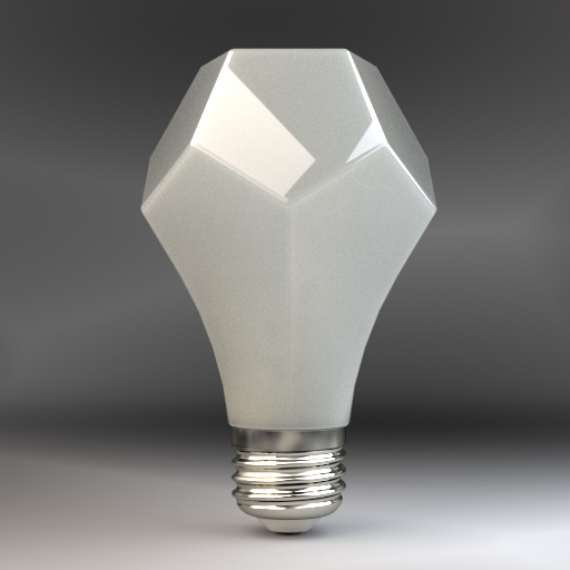
Result:
Note:
Thank you very much. You helped me a lot. The current result is pretty fine for me.
Best,
Eugene
I didn’t test any of my sugestions, while my pc is still occupied with other tasks, but this is something that I would like test.
As for the light path in this material, SSS is not enough. As the light comes in, just a small percentage will follow the SSS path, with light being reflected back from below the surface.
The most will continue not in a straight direction, that’s where the translucent would take part, and some light would go in a almost straight direction, like in a refraction with some roughness.
(the reflected light can just be easily represented by the glossy shader, with the fresnel factor)
Sure it’s an interesting problem to solve in Cycles’ way of dealing with light.
its not a shader issue, you are looking at. obviously the material of the real milky glass has got some variance in density, due to its production process. melting glass and cooling it down again in a definite shape will always end up in varying densities. these lead to darker and brighter scatter/absorbtion. you will have to define them by hand. so to speak you wont get a satisfiing result if you leave the work to the material. i would setup a map and paint the dark areas by hand, to use it as a multiplier for the shaders (fastest way), rather than try to achieve it by a nodesetup. furhtermore i’d use a glass material instead of a glossy, to get rough refractions. and last but not least use volumescatter and absorbtion as the volumeshader. the raylength method is a good tool to make unrealistic (stylish) volume effects. since you want to achieve real glass, you should stay with volume shaders, they were made to do the job.
@mn-8
That’s what I discovered recently. The dark areas on the edges are caused by the production process and can’t be achieved by a simple shader.
Big thanks for your advice - it’s so simple.  Why I didn’t thought about a map to control the density variation? :o
Didn’t check the volumetric shaders yet. Will give it a try and report back with the results.
Cheers,
Eugen