Clock, I may have missed this reading the thread, but I presume there is some lighting to assist the engine driver. Will this be by gas mantle or incandescent electric lamp?
“Propane Gas Lamp with Mantle” is what it says on the drawing for cab lights - electric incandescent lamps were available, but considered a waste of electricity that could be better used propelling the loco forward, or backward, rather than keeping the driver comfortable. Besides the driver(s) would be used to such gas lamps in their homes, and the thought of turning on a light switch might be alien to them. The loco had a crew of 2 - Driver and Technician; a sort of flight engineer as on a plane these days, whose job it was to keep an eye on things and he could get into the workings through the back door of the cab if required. This would be fine as “Health and Safety” hadn’t been invented by the Victorians, nor was it ever thought about until long after the Old Queen died (and by that I mean Victoria…).
Cheers, Clock.
PS. I have a real surprise up my sleeve for the crew… :yes:
EDIT:
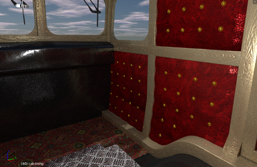
Buttons on the cab lining: 
Now I am definitely off to bed…
As I take it, these were some sort of a hidden, conspiracy-esque project that was evacuated due to money and bribery? Are there any pictures of this online? A quick look under R. Stephenson’s name, followed by what you’d said it was turns up nothing.
Hmmm, no big surprise there as it was hushed up and quietly forgotten about. There is apparently one picture of it in existence, although it is in the background of a train wreck photo. I am looking for it and will post it if I ever find it.:eyebrowlift:
I have knocked up a seat for the driver - much more detail to come before it is finished, but its a start, along with the parking wheel brake control:
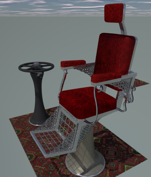
There will be a seat for the Engineer as well, but he will face the instrument panel. I used an “Erk” from my Canberra project to get the proportions correct, I am not sure yet who the seat supplier was, but I will let you know once I have got to the bottom of this. 
Cheers, Clock.
Said Erk, I pressed the save button too soon… Old age you know is a terrible thing.
Cheers, Clock. :o
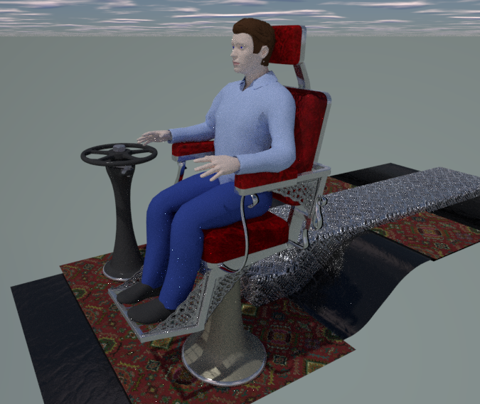
And… here is the Engineer, Oh yes - he’s back… 
So the Engineering is sorted out, the driver will change for the final cut, this driver was just to get the seat proportions correct. I need to do some work on Erki - I will need to switch his main power off - he seems to be a bit stroppy at the moment…
Both seats will rotate for the occupants to get on and face the way they need to be looking, Erki should be keeping his eyes on the control board, that I haven’t made yet, maybe when I have he will calm down a little. :no:
Cheers, Clock. :evilgrin:
Ha, ha the Victorians clearly had a sense for technical interiors  Nice carpets and plush in the driver’s cab.
Yes my friend - very comfortable, there is a lot more to go in there, but maybe I should look at the remaining major bits, like the electric bits that go in the big hole in the loco… so much work still to do, but this is a long term thing to get absolutely right. I would be grateful for any critiques on my modelling, texturing, etc. for the bits that are showing signs of being more like what they should look like.
Last one for today - all the meshes in view - 2.67 million faces and my Mac is getting warmish… :yes:

Cheers, Clock.
I have had some success with the “Wegelphleffer” over the weekend. I found a paper, which mentions the device, that was published by Cambridge University faculty of New Technology authored by two professors: Josiah Isaacs & Septimus Middleton in which they state that it is a ruse to disguise the real device, as my good friend @minoribus had suggested to me. This paper states that the real thing is in fact a “Phase-Shifting Voltage-Thrumming Discombobulator” and that “Wegelphleffer” was it’s code name - hence why it is in quotes on the drawing perhaps.
This paper is countered by another from South Princetown University’s Nathan Kingsley, who argues that the less common and more simple Linear-Smoothing Discombobulator is a better alternative. Me, I prefer to use the PSVTD and this was also the opinion of the loco’s design team. Let’s face it you never hear of the Linear-Smoothing Discombobulator these days, so it must have been disregarded as of limited use only. This is good news for my project because I know exactly what one of these PSVTDs looks like and can now make it. :yes:
This device is used to produce a square waveform, positive, fixed frequency, electromotive potential from AC generated voltages and is ideal for feeding the speed controllers for the traction motors. As I thought, it is not a rectifier, as this produces flat waveform DC voltage and is of no use on this loco. :no:
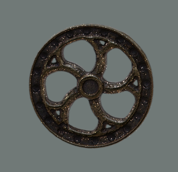
On a different tack, I have also made the control wheels for the many valves in the air system, this has yet to have the handle, securing nut and shaft added, but its a good start:
Cheers, Clock. 
PS. I am pleased to note that some of you at least understand this technology, clearly @Jaxtraw must have worked in this area as well to understand thromulator technology so well. Are any others similarly experienced who might help with the project?
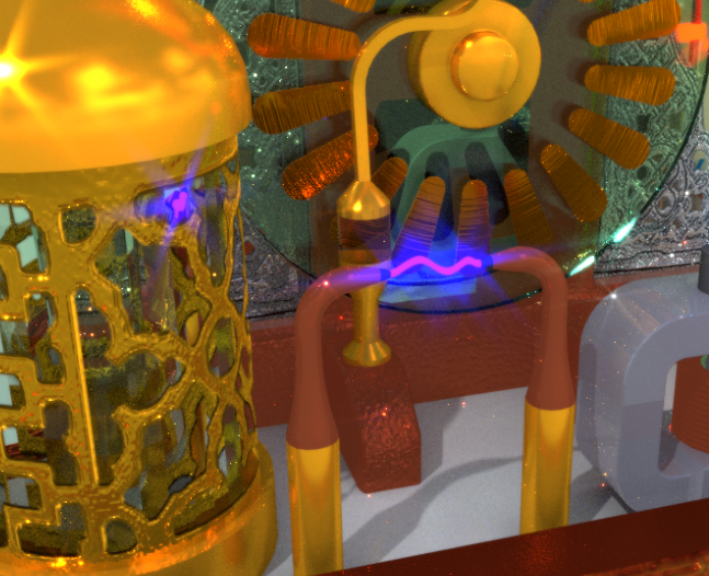
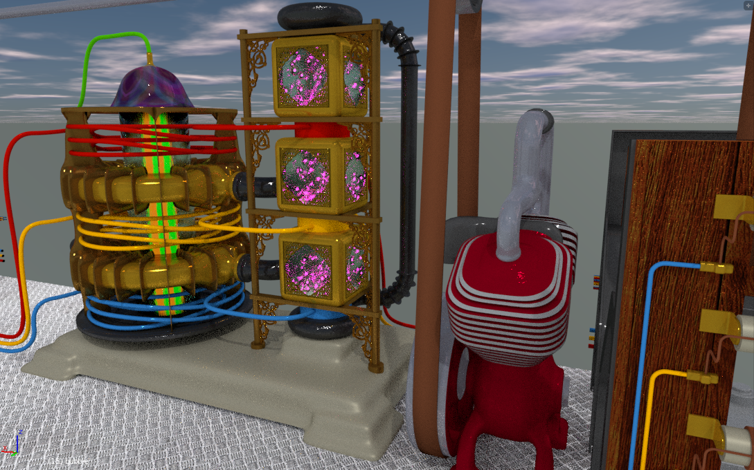
Here is the Thromulator Resonant Coupling Debigifier module, or TRCD and part of the Turbine Engine Management Unit (EMU). See posts #15 & #16 if you are wondering what this might be:
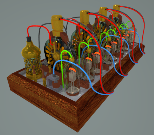
This is not finished yet, more details to add, but the basic functions are in place. It works by the thromulators sending electric current to the little brass motors, which drive the glass plates in opposite directions per pair (there are four sets, one for each pair of thromulators) This causes static electricity to build up in the Leyden jars with the ornate brass covers. Once the static electricity in the Leyden jars gets too great, caused by excessive resonant coupling, the jars discharge through the copper spikes at the front (an electric spark appears) causing the relay to shut and this sends an electric signal back to the thomulators, using the blue wires, to adjust their settings. :eyebrowlift2:
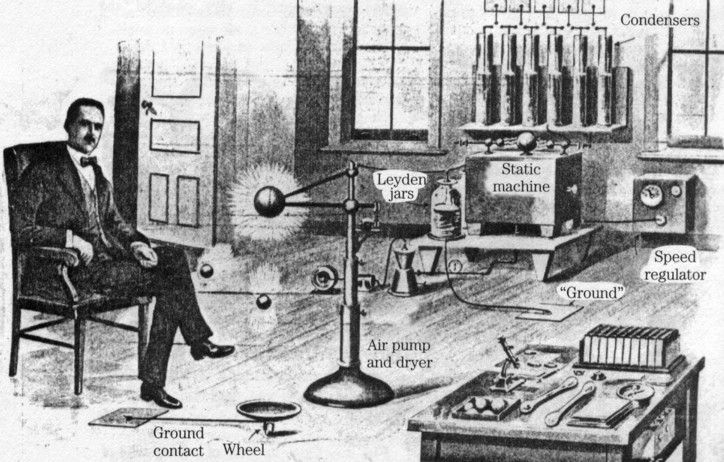
This module was designed by Theodore Ibertson-Thorndyke of Thorndyke International Electric Systems Ltd. Below is a picture of Dr. Theo. Ibertson-Thorndyke carrying out experiments with static electricity prior to building his prototype TRCD:
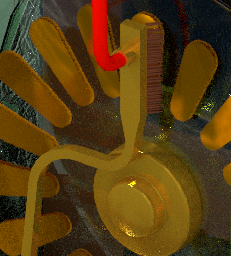
I used a hair particle system to get the brushes that rub on the brass sections attached to the glass discs - these brass sections were modelled using images and transparent shader nodes. Here is a detail of the brushes:
Cheers, Clock.
Here’s the spark, I have also revisited the brass sections so they have scuff marks from the brushes:
These are only “rough” renders for now - I will spend much more time on the materials, environment and lighting later on in the project.
Cheers, Clock.
Thromulators, TRCDs, Discombobulators (you know there was a bender plugin for that? https://blenderartists.org/forum/showthread.php?337368-Discombobulator-Plugin  )
)
… I feel that this loco is a very clandestine science And I’m sure that Theodore Ibertson-Thorndyke of Thorndyke International Electric Systems Ltd was very proud, when he invented that. But as you said - at that time it also was very dangerous to question the reign of fossil energy sources. No wonder that he used the alias “Mr Piggott” at some occasions 
@minoribus ref: “Mr Piggott”.
Aha! not only are you an excellent Blender Artist, you are also a very good detective, but consider this:
Both you and I disguise our identities here, with nothing really to lose, the good doctor, however lived in a more brutal world. If it were known what he really did, he might be subjected to bribery (bot too bad), blackmail, some temptress of ill-repute in a whalebone corset getting him into trouble (not quite so good in the long term), or worse still violence, up to an including “murder most foul” (not good at all) to keep him quiet - so a pseudonym was probably a good idea. I think it is safe now to reveal his real identity as he has long since “shaken off this mortal coil”.
Cheers, Clock.
EDIT: I take it you are referring to Mr George Samuel Piggott?
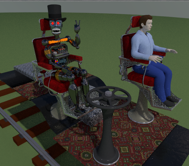
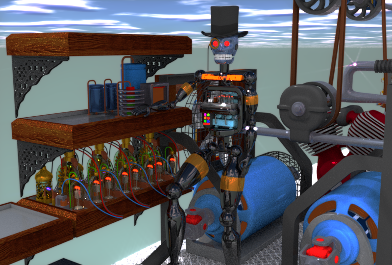
I have given Erkinator a job to do - work on the EMU and other electrical bits. I think I will get him to do some of the wiring as well whilst I get on with some other bits. In keeping with the project he has now “gone Victorian” and taken to wearing a monocle and speaks of the “water closet” rather than the toilet for example. He has also discussed with me whether woman were allowed to drive trains or motor carriages, I told him that at this time they were not, he seemed a little upset with this, but I guess he will get over it. Here he is trying to look like he is doing something useful near the partly completed electrical modules:
I have also discovered the identity of the chair makers; three Italian gentlemen emigrated to the USA in search of the “roads paved with gold” and instead developed the new fangled technique known then as “Chromium Plating”. They became very adept at this and began producing chairs for Barbers, Dentists and Ladies Coiffure Emporia. Such was their reputation that the loco designers decided to give them, now known as Franchiti, Ascari & Nutini of New York Inc. the contract. Sadly, however, they thought that there would be much more work in the field and they bought lots of equipment for the forging and chromium plating processes, only no further contracts came, due to this project being “shelved”, and they filed for bankruptcy and returned to Italy. 
Cheers, Clock.
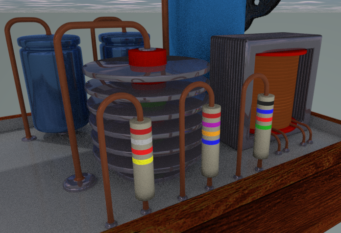
I have made some colour coded resistors - I just have to move the UV’s over the colour image to change the values: :eyebrowlift:
Cheers, Clock.
You can see the transformer for the electronics, the capacitors and the rectifier also in this image.
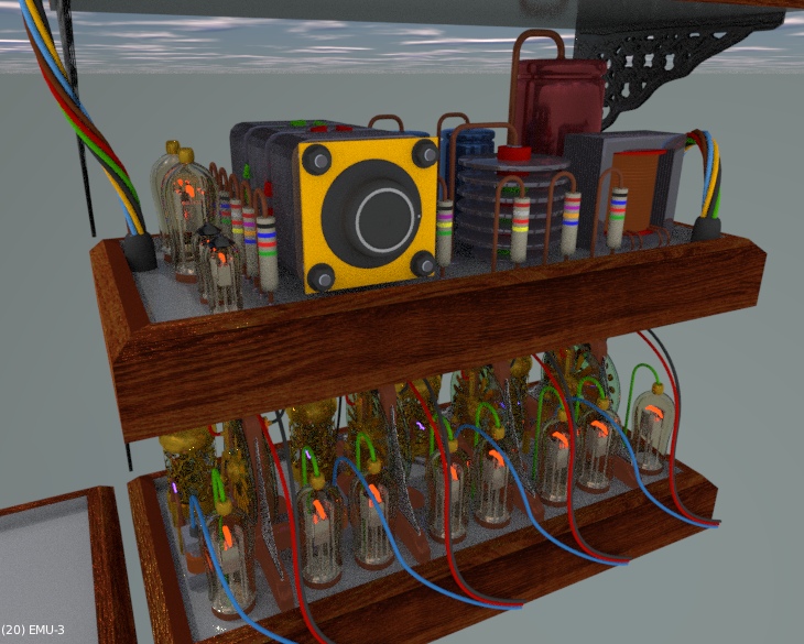
First stage of the Turbine EMU added to the TRCD module - one more layer and the side section to go…
Getting better at soldering now. Does anyone know how this works? electronics was never my strongest subject. :no:
Cheers, Clock.
So here is the next major bit, “roughed out” - lots more detail to go and more small parts:
I will explain what it is and how it works later, I need a bit of rest now. :yes: If anyone has any guesses as to what it is; please let me know.
Here is a closeup of one of the “chambers”:
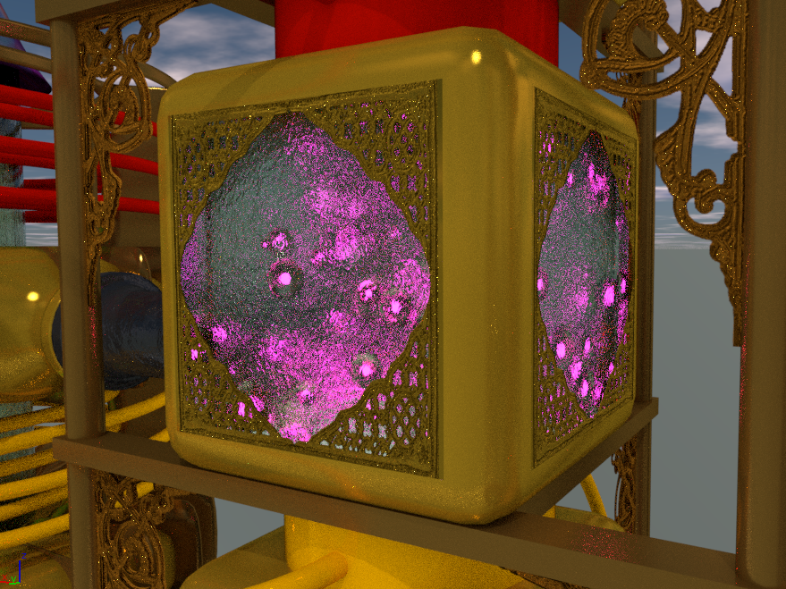
Cheers, Clock.
By way of a clue as to what this bit might be, I found an old Brass Rubbing of a sign that was placed somewhere on this piece of equipment, exactly where I have still to discover, I have reproduced the sign, as was, with some concern as to the exact meaning of it:
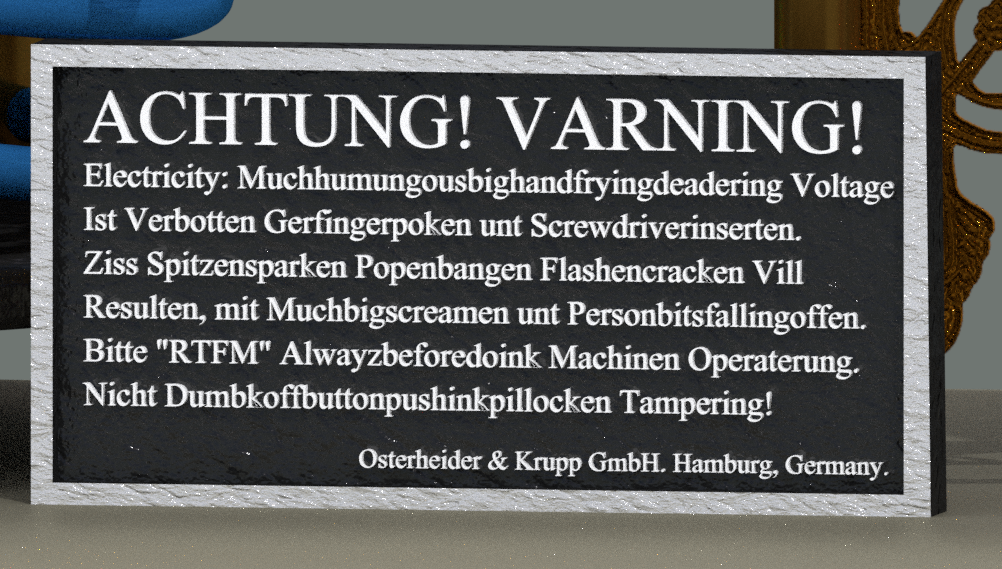
It just goes to show that translation services during Victorian times were in their infancy, even between close neighbours. :eyebrowlift:
Cheers, Clock.
The TRCD looks very finely made. I look forward to seeing the famous Ibertson-Thorndyke brass plate to identify the designer/manufacturer when you are completing the finishing touches to this marvellous loco. However to my eye, those condensers (as capacitors were known) look a little too modern to my eyes; also the wiring would have been insulated with vulcanised rubber or gutta percha, the colouring of which tends to be rather muted. Back when I was starting as an electrician there was still a lot of VIR (Vulcanised India Rubber) wiring to be found in installations; the black is a bit of a muddy dark grey, the red is more brown, the white is sort of yellowish off-white, etc. I wouldn’t expect bright colours on wiring of this vintage. I think I might expect to see substantial copper busbars and brass terminations on this machine.
Of course this is speculation as I do not have your archival resources that you can work from. Also, I think sadly this is a little early for the visually glorious mercury arc rectifiers to be used for rectification to direct current (as a youngster I actually saw some in operation, truly beautiful) but I wonder if this advanced project may have contained some similar, earlier technology?
Very cool!