Hi all, as you know, cutting a hole on a curved surface is always a puzzling issue. The key to the solution is to add edge loops around the hole without distorting the remaining curved surface, but it isn’t just as simple as it sounds.
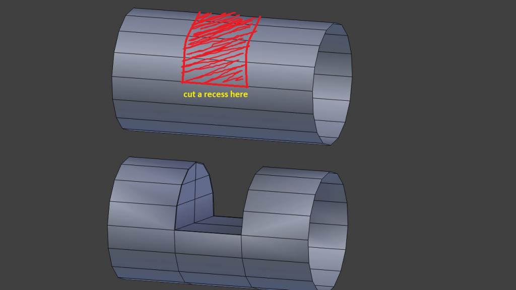
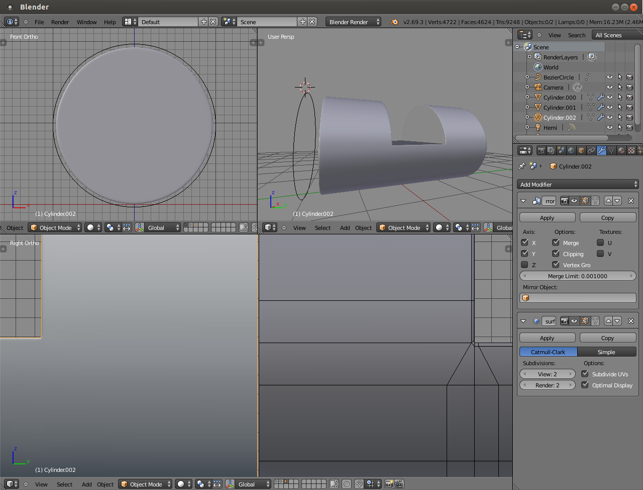
I have a tube (with subdivision enabled) and want to cut a recess on it.
The image should tell my purpose clearly.
That’s it but…it isn’t that easy, it’s the subdivision that makes the curved surface hard to control.
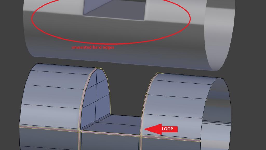
Now I want to add some edge loops around to make it more handsome.
I had tried a few solutions but none of them could bring the desired result.
First, adding edge loops to any edge around the recess
Result: there are still some unwanted raised points on the curved surface :spin:
The other solution I can think of is applying the subdivision before cutting the hole, but that will increase the vertices unnecessarily. Hope someone can help me with a cleverer method.
Thanks in advance.
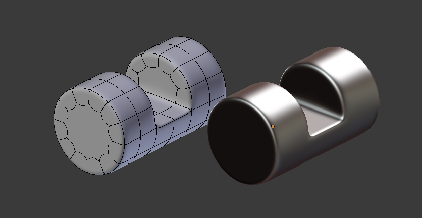
Edit: I forgot, this does create four huge n-gons at the corners. You’ll want to merge the vertices at the bottom corners to make triangles in the beveled portion so your cylinder doesn’t suffer from having n-gons when you want to smooth.
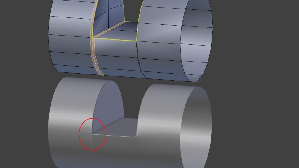
No need to resort to creases which have a lot of disadvantages; just terminate those horizontal loops. If you want the edges as sharp as in your original image you’ll have to start with a cylinder with a few more edges though.
Well that’s four.
The first one is only sort of true (the normals are calculated per vertex so it looks like the radius is changing, yeah). This is essentially a non issue as long as you keep your polys sub-pixel in size.
The second is very true, you still need proper topology most of the time.
The third is kinda unimportant. Yeah, there’s some overhead. OpenSubdiv should solve that eventually. Still, artist time is more expensive than render time.
The fourth one is not so much that there’s no guarantee, but that it just doesn’t work outright. So you’re right, that sucks. The good news is I have sent Campbell some sample fbx files with creases and he agreed to include them, so it should be solved sometime between now and the end of the world.
On the other hand support loops have their own disadvantages.
They make the model annoying to edit after they’re already in place.
They make the model annoying to unwrap.
The uneven mesh density doesn’t lend itself particularly well to sculpting or displacement mapping.
i cant reproduce your problem, this is how i do it.
create cylinder with 12 sides use a cube and a boolean to substract a hole (because its simple)
Next i go to edit mode select all ans set the cylinder set shading to smooth.
Next on the flat cut, select that surface and make shading flat.
next add edgesplit modifier; catmulclark sharp edges, edge angle 32 degrees (or a bit less)
Next do as many subsurfs as you want
works.
Hmm. Subsurf after edgesplit usually returns floating geometry for me. May I see a blendfile in which that works? I’m probably missing something elementary in the setting.
thank you for your quick respond.
your methods work well, but unfortunately it isn’t well enough
in case I need really sharp edges, I have to tighten the space within the edge loop and that will create some artifacts :no:
the below image is the result of using bevel (as K Horseman suggests)
using crease is not good enough to create sharp edge either (set the crease value too high and it will destroy the subsurf effect)
I’m not sure about the Edge Split method, can you post an illustration image, PGTART ?
thanks, high poly and without subsurf, the curved surface is easier to control. Unfortunately my project sticked with subsurf at the beginning :o my bad habit is to create really low poly, then depend on subsurf for smoothness.
Having the cutout on 90° angle helps to keep the circular shape. Started with a mesh circle with 14 vertices on this one so that one loop cut needs to be added for the cutout to start from the middle: