Hi,
There is a tutorial out there, for rigging the wheel of a car, it is for Bl 2.5 but
in the latest (from this morning) I get some strange behavior.
I include three pictures, the first shows the partially prepared model with two
bones of a car_rig.
the big box is parented to the ‘base’ bone (works nice)
the right frontwheel is parented to the second bone BFwheel.R (works nice)
the white part of the wheel is done by rotating in y direction BFwheel.R OK so far
Parent bone of BFwheel.R is base and indeed if I move the base, the box as well as the second bone with weel moves OK
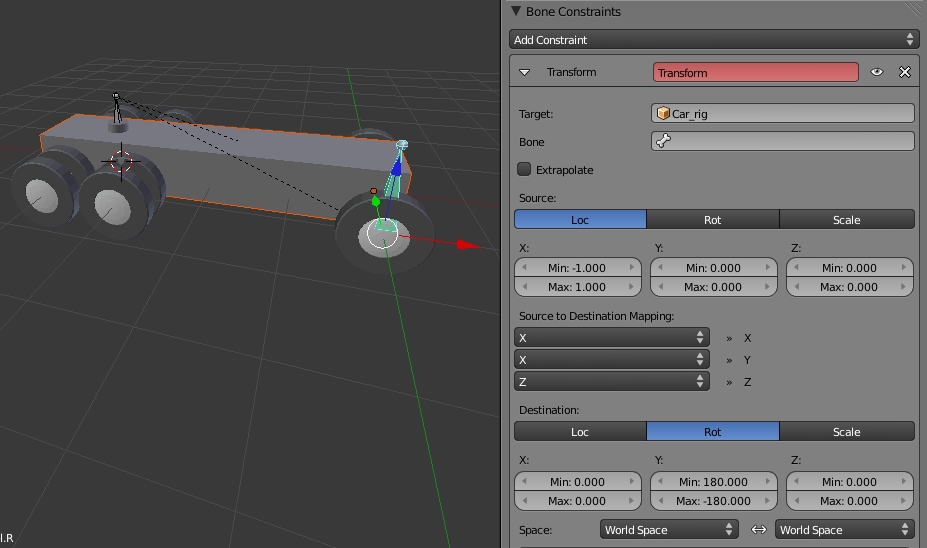
Now the tutorial says: make a boneconstraint to let the wheelbone rotate in y direction if
the base bone moves in x direction .
And now the strange behavior to be seen in picture 2 and 3 …
If the BFwheel.R gets its target base, the bone and wheel rotate???
What am I missing?
By the way, knowing that this strange rotation will happen and rotating the wheel (and bone) I once got what I wanted
not only set the y-rot-destination to -180 up +180
set the x-rot-destination first value to +90
to get the bone again into its up position from the restpose.
(maybe the value +90 is wrong, but if you change those,
you may see the bone “go back” into its “old” position).
ps. this rigging for rotation will only work as long the
object moves along the x-direction.
update, edit: another way would be to set the origin-bounds for
the x-rot-destination to a fixed value -
reason is, you cannot exclude one channel from the transform,
so with the defaults bounds -0 up +0, there is the map from
value 0 to the rotation and this is not the ZERO-rotation.
If you want the front wheels to follow the road track, shouldn’t you rotate the wheel arround the z-axis?
Rotating around the y-axis should make the wheel spin and what I actually see is that the wheel is rotated around the global x-axis.
If the tutorial is right perhaps you have to readjust/clear the object origins and/or loc/rot before applying the rig?
I had no idea that s/o is really trying to rig the wheel rotation. It seems to me like modeling the piston movement inside the motor block as well. As I haven’t seen the video yet, I will give it a try to look into your blend file (on next weekend). In the meantime test-dr's answer seems to be logical for rotating the tires.
I had a look into the tutorial on Blender Cookies to find out what they are rigging.
First of all you designed your model heading along the x-axis whereas the car in the tutorial is placed along the y-axis.
The other problem is that you should use the local (drivers seat) orientation when rigging the car, not the global orientation. You want to rotate the wheels in relation to the heading direction of the car . But you are using the global coordinate system. I believe a car should behave the same regardless of where it is placed on the globe So just switch the space information in the constraint box to “Local Space”
One last thing is the setup of the constraint box itself. According to the tutorial they want a 360° wheel rotation for every BU the car is driving along its local heading direction.
So driving forward 1 BU should turn the wheels 360° ccw, driving backwards should rotate the wheels 360° in the opposite direction.
That’s what the translate constraint is doing. The source is the location information of the (local) leading bone axis running from +1.000 to -1.000 blender units. Depending on your cars heading direction the destination shall be a rotation information running from -360°(ccw) to +360°(cw) or +360°(ccw) to -360°(cw) .
So you should fill in 360.0 for the rotation value. Using 180° will cut down the rotation speed to half the value. And you have to tick the “Extrapolate”-box as you want the wheels to turn 360° for every BU movement in x-direction. Without selecting “Extrapolate” the wheels will spin within a section of +/- 1BU from the center only.
OOOPS I forgot to mention that you have to fill in the leading bones name into the “Bone”-box.
Ha, “OOOPS I forgot to mention that you have to fill in the leading bones name into the “Bone”-box.”
That is just the BASE of my question!
In the blend that is not just done YOU should do it and seeing the wheel rotating some 90 degrees !!!
The other things you mention are clear and OK behalve of one thing the author (you too?) of the tutorial is not aware of (I think at least)
moving the car 2 (-1 … 1 Blender units) the wheel moves 2PiR = 360*R (-180 … 180) and most of the time this is not 2 isn’t it?
The bones are fixed to the wheels center of rotation so there is no distance value like radius or diameter involved at all. The translate modifier just translates 1 BU to a revolution of 360 degrees no matter if the wheels are tiny or for a monster truck. And if you are moving the parent 2 BU, the wheels will rotate 720 degrees.
And for the rig parenting you need to setup the master/slave-relation before doing any fine tuning as this is IMHO the most essential part in rigging. Why should I try to investigate on s/t if the setup is not done like intended in the tutorial.
My suggestion would be to restart from scratch and follow the tutorial. That’s what tutorials are made for :eek:
When using the rotation transform properties of the target as input, whatever are the real values, the constraint will always “take them back” into the [-180°, 180°[ range (e.g. if the target has a rotation of 420° around its X axis, the values used as X input by the constraint will be ((420 + 180) modulo 360) - 180 = 60°…). This is why this constraint is not really suited for gears!
Internally this seems to be an modulo 360° operation, however the relation 1 BU = 360°, 2 BU = 720° still applies. And we are using location properties as input values, not angular rotation information.
So now done … and the car in z-rotated direction, behaves good (the bone constraint adding moves already the bone which was in the other direction of the car just not wanted and had to be foreseen … so problem solved)
But one remark to the TUTORIAL:
It is worthwhile to make ONE bone to rotate a wheel … and then copying by Shift D copies already the bone-constraint (and other things)
and my car has so to say 6 wheels … (some double) so the handwork is nicely reduced


 behalve of one thing the author (you too?) of the tutorial is not aware of (I think at least)