Can also use fact that Poisson distribution works in 3D… explained here by SterlingRoth.
2 Likes
Points Inside Mesh
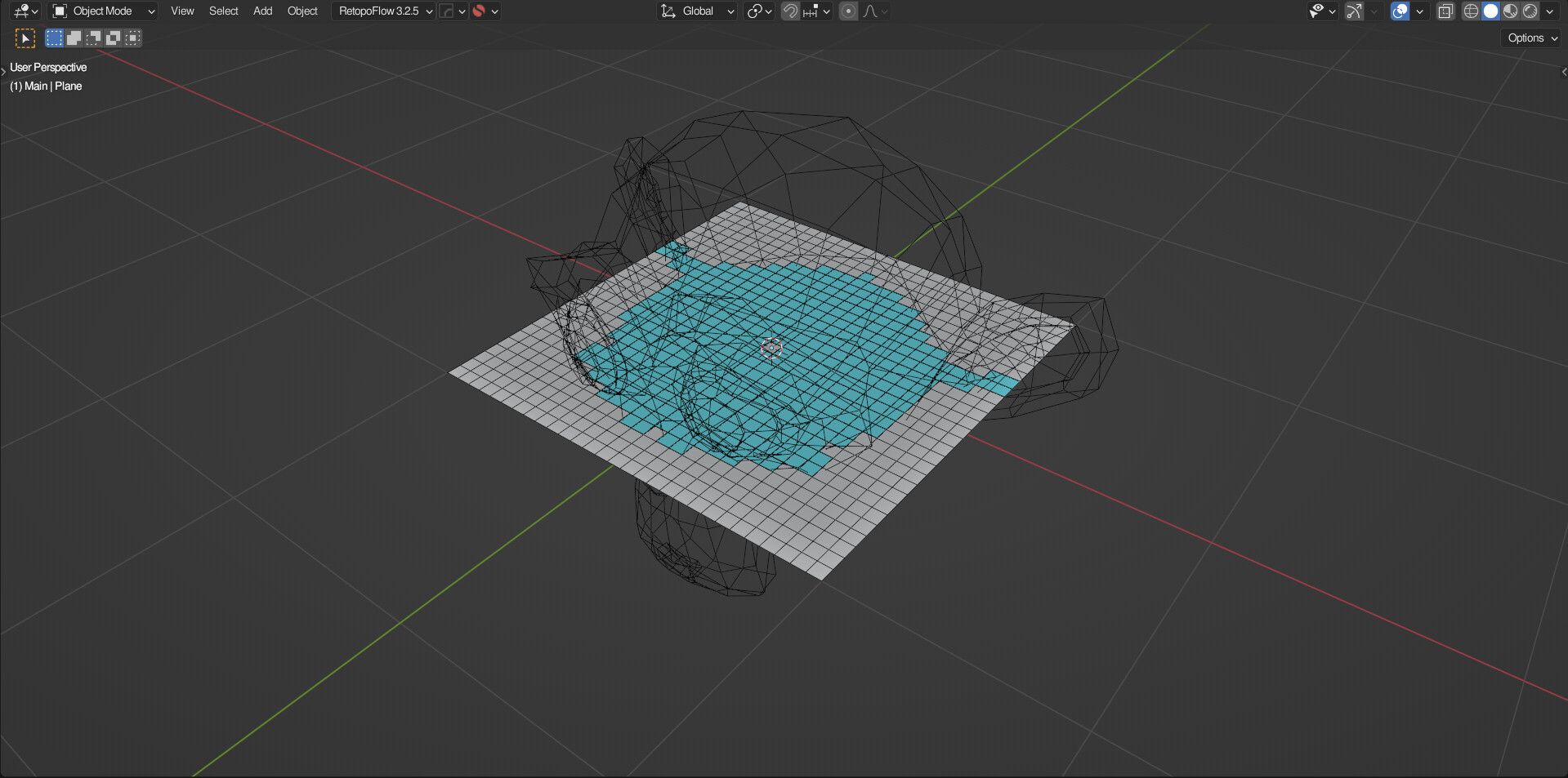
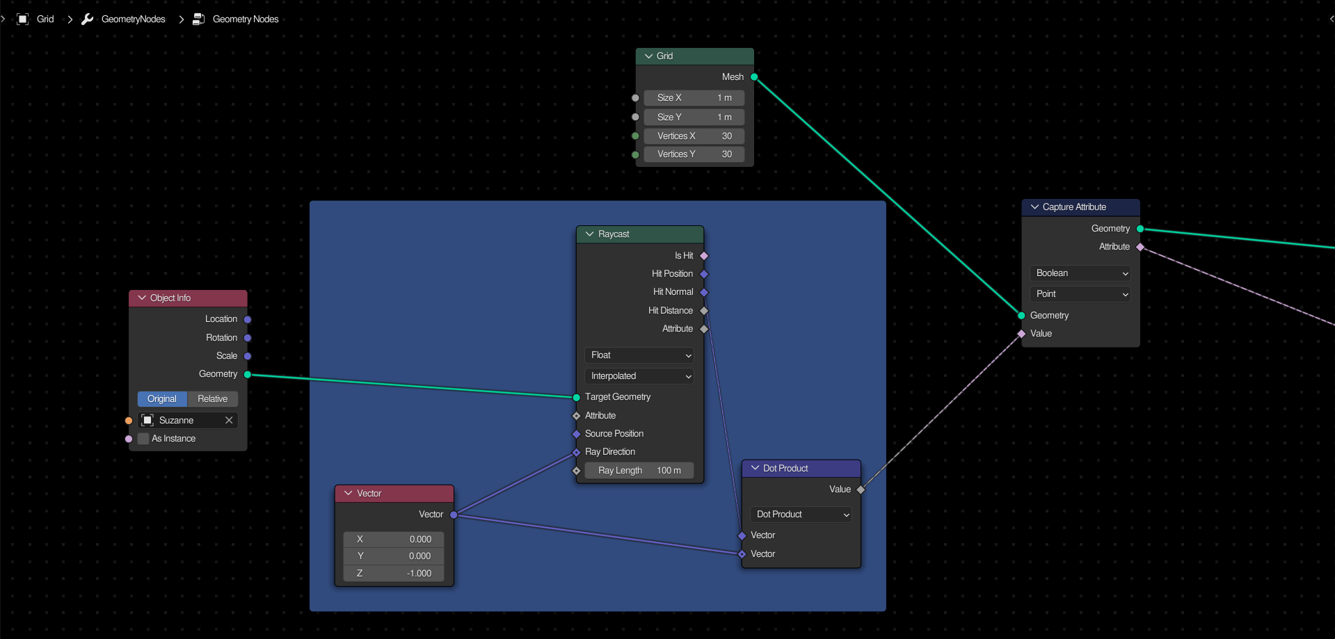
To select all of the points (or edges, or faces) that intersect with a different mesh, use the raycast node and use the a vector node to set the direction. You can then take the “hit normal” attribute and take the dot product of this and the original vector. Capture it for later use.
4 Likes
Distribute Points in Volume

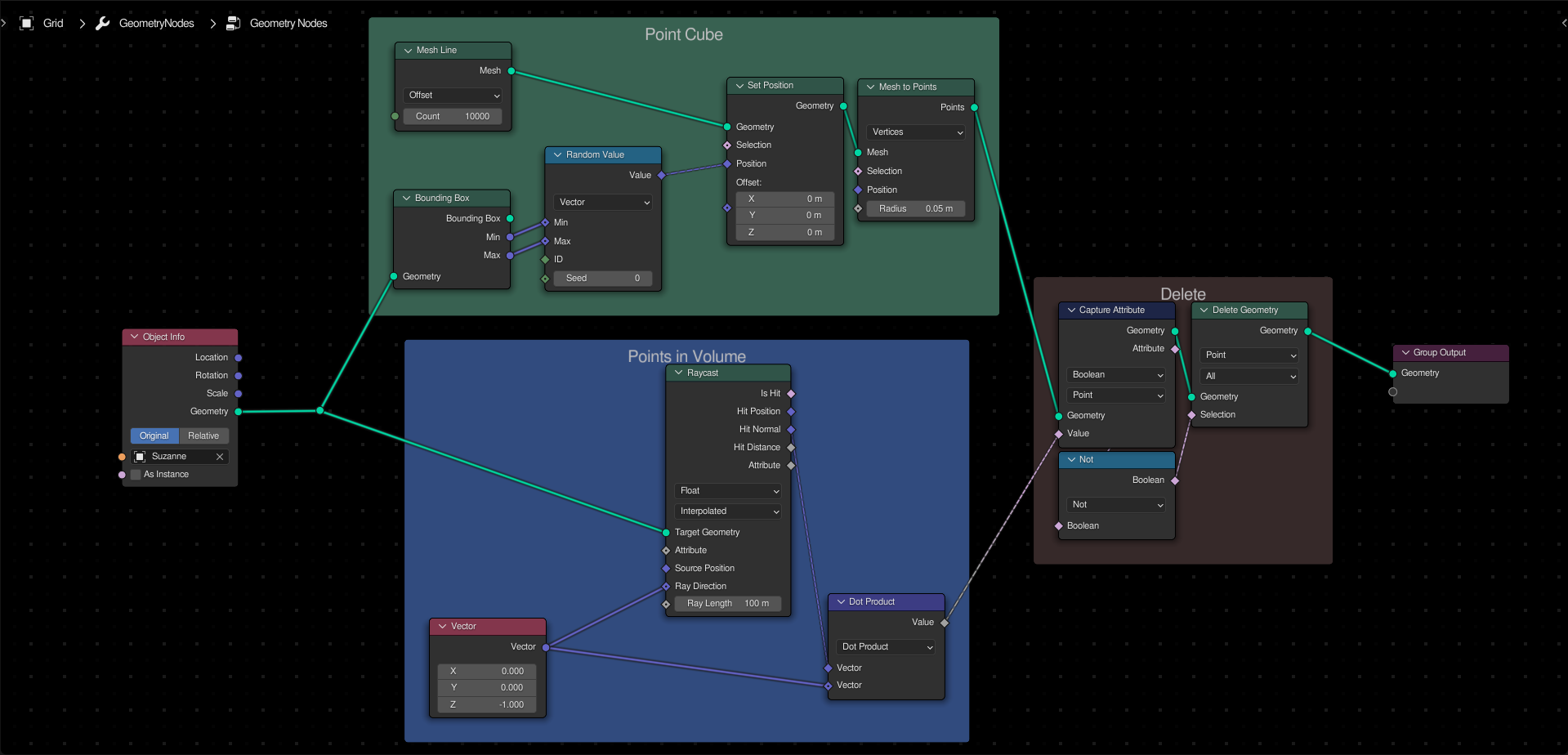
To randomly distribute points within the volume of a mesh, first create a point cube using the bounding box of the original mesh to set the minimum and maximum position. Secondly, select all points which are not inside the mesh.
5 Likes
Should add a list of all the actual recipes in the first post that link down to the recipe posts.
2 Likes
Noise Displacement with Linear Light

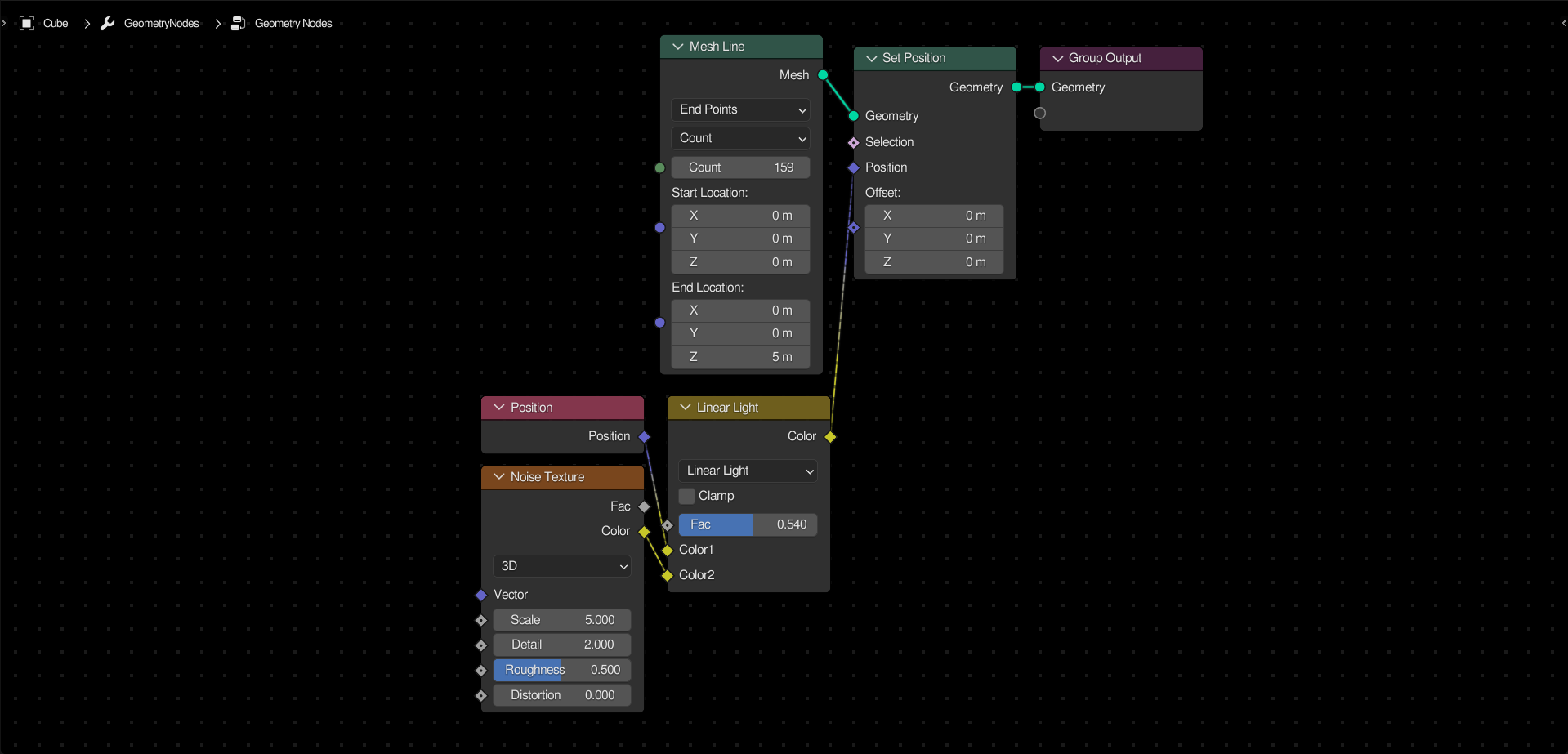
One important thing to take advantage of is that the Linear Light blending mode will add values, but using 0.5 as the midpoint instead of 0. In effect, this will allow you to evenly displace points using a 0-1 texture, such as the default noise texture.
This is great for displacing meshes that have no faces (hence no outward normals) to set the offset direction.
10 Likes
Great idea, that will help separate the comments and discussion from the actual recipe posts, and make it possible to skim the list for a specific effect.
We might need another one of these but for the super simple concepts (which are kicking my ass). I like how these buid on top of each other but there are even simpler concepts that I assume will build on top of each other that I still have zero clue about.
Custom Instance Probabilities
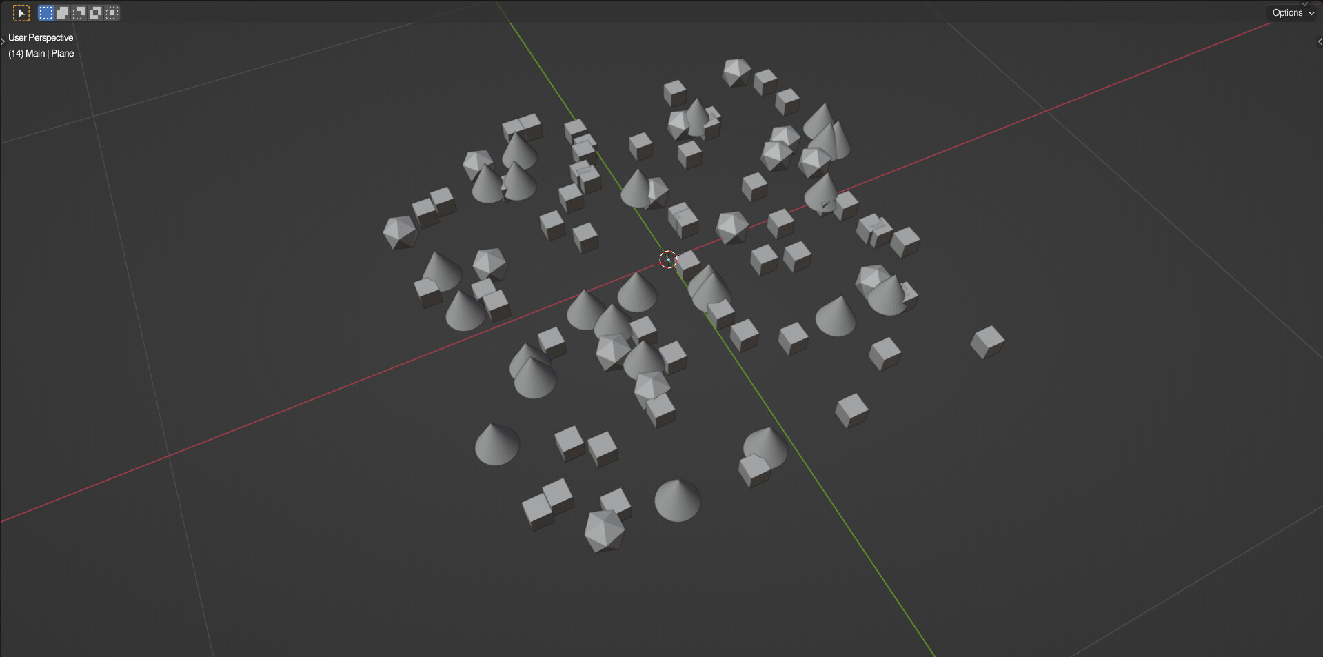
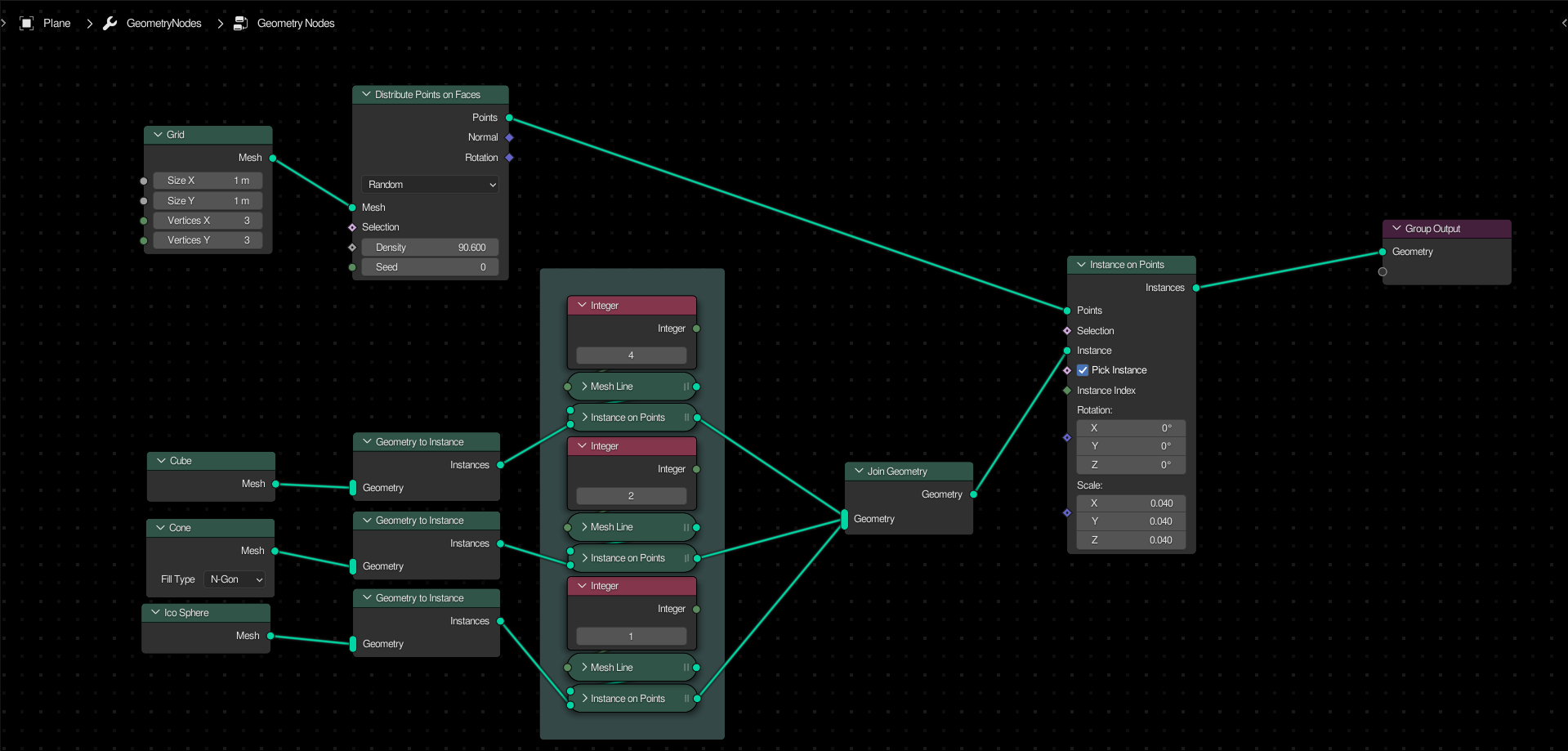
In the above example, cubes should appear roughly twice as often as cones, and four times as often as ico-spheres. To achieve this effect, simply duplicate the instance (via the instance points node) along a mesh line primitive. Changing the count of a line will make that instance appear more often. This works similarly to the “use count” option in particle systems.
This is a great way to have artistic control over asset scattering. If a certain asset is too visually distracting, and is taking important focus off the subject, simply set it’s count to a low number, and up the counts of other assets.
Note: In order to avoid unwanted offset, it is necessary to set the offset of each line to 0.
2 Likes
3 Likes
Interesting. I had no idea that was possible. This is a useful solution too!
Knurl Effect
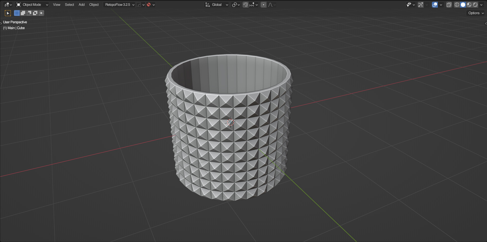
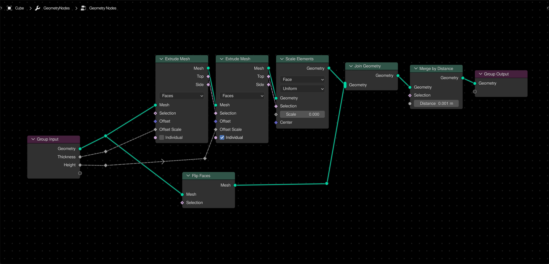
To create a procedural knurling effect, first use an extrude node to solidify the object. Use a second extrude node, this time setting it to individual mode. Take the top output selection, and use it to scale the top faces by 0. Finally, join geometry as needed and merge points by distance.
2 Likes
Knife Boolean
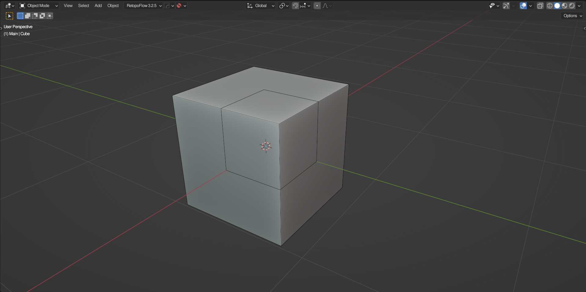
Sometimes you want to cut custom edges into a mesh, affecting the topology, but not the overall shape. Luckily, it is possible to do so procedurally through geometry nodes.
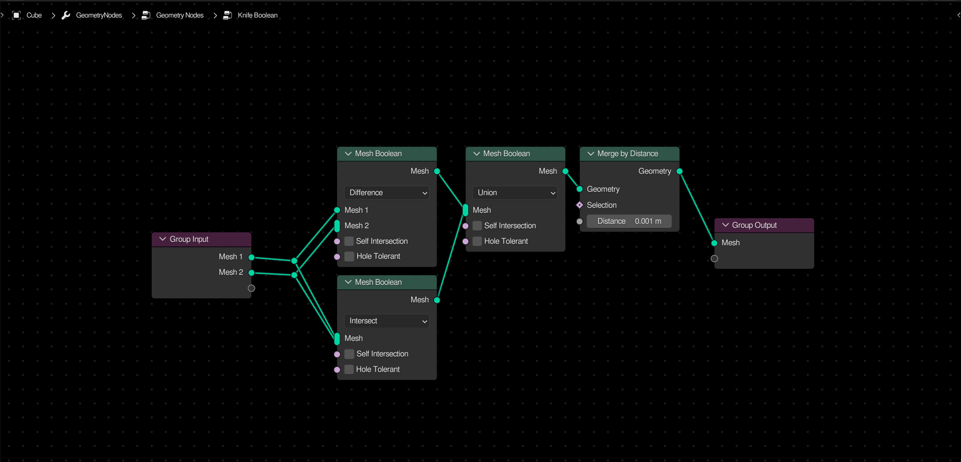
Simply take the difference and union of both meshes and union those together. The merge by distance node shouldn’t be necessary, but I never trust booleans, so I put it there just to be safe.
Keep in mind that when using booleans, errors and artifacts can be frequent. But when applied properly, such a setup can be incredibly useful for complex effects such as this:

3 Likes
I really wish there were demo files attached. I’m trying this one out and getting no results.
Hey, sorry I am late but this solution does not work for all cases. I only works as long as the origin is contained within the mesh (it is more complicated than that). Which means cases like these don’t work

The foolproof method is to take a dot product of the hit normal and ray direction (in this case 0,0,1)

1 Like
Ah, I see. Thanks for the more accurate setup.
My setup:
Took the distance from the origin in every direction (aka position) and implicitly converted it to an angle vector. All points that were not hit by rays were left behind by the delete node. Since position zero is defined by the origin, it relies on the position of the origin, resulting in some weirdness.
Your setup:
Shoots rays in one direction, takes the normal of the hit faces, and combines these two vectors by taking the dot of both of them.
Since your setup takes the normal into account, it’s easy to see why it’s more accurate.
It’s probably possible to invert the setup, using the normal as the ray direction, and using the hit position instead of the hit normal. Would this work? Though it wouldn’t have any advantages, it would be easier to understand what’s going on.
The points don’t have normals. This setup actually kind of intuitive though. If the ray hits a backface- keep it, else delete it.
Well, thanks for the info. I’ve updated the posts to match.
1 Like
So I just wasted my day trying to do this with math nodes. Is there any way to do it with just math nodes?
Also is there a way to displace only along the x and y in positive and negative and keep the original z values?
Update - I came up with this

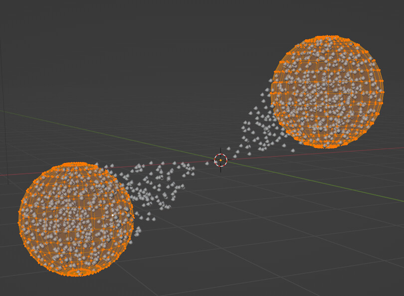
Override Named Attribute
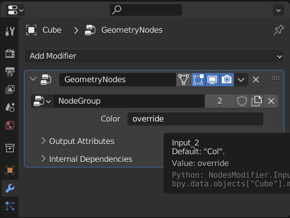
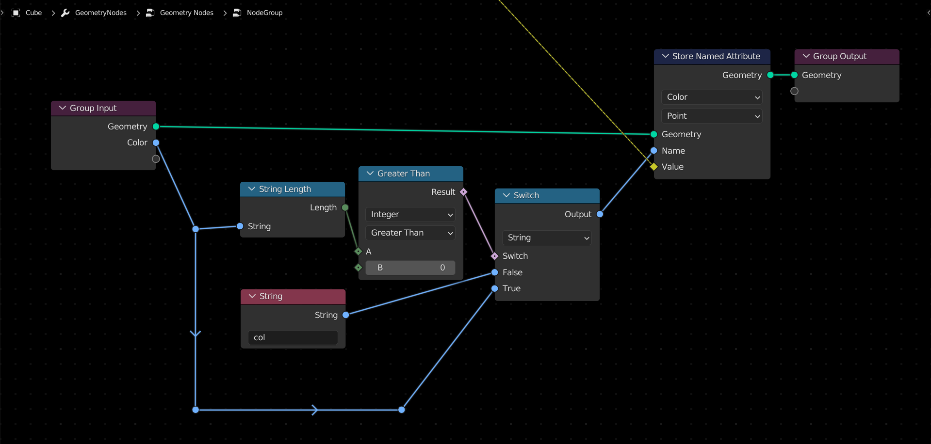
When working with named attributes, it is best to avoid name collisions. One way to do this is to set a default attribute inside the nodetree, but switch it using a string length node if an override has been set in the input.
This is a great way of balancing flexibility and shareability.
3 Likes