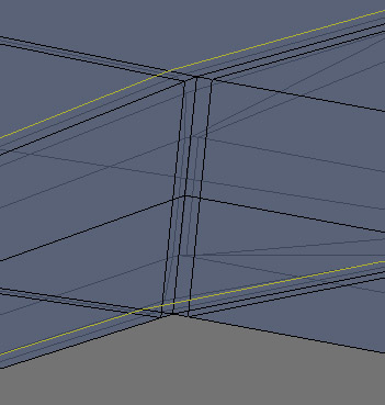
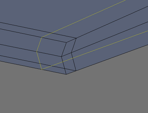
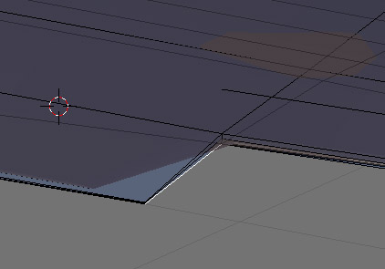
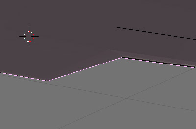
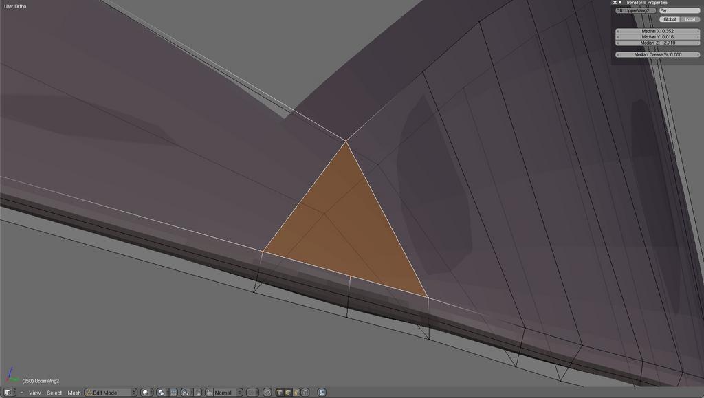
I’m busy trying to model a WWI Albatros D.III biplane. I’m having a few problems with the upper wing. The wide shot here (top left) shows the upper wing (only half as I’m mirroring it), and as you can see it is getting a little complicated. The other two shots show more detail around the edges of the cut-away I’ve made for the ailerons. The aileron cut-away needs to have some nice 90 degree angles, which is a shame as subsurf and smooth are working hard to make sure everything is getting rounded. I added some edgeloops at the inner part of where the aileron joins the wing to stop it being rounded out (top right, the yellow edgeloop is on the upper and lower surfaces, a continuation of the added loop in the bottom right diagram from the wing trailing edge) . I also had to add 2 where the aileron cut-out meets the wing trailing edge (bottom left). I had to add them to both sides of the corner, and of course I now have thin slivers going everywhere, which makes some of the views well, a bit untidy really.
I’m wondering if anyone has any advice on how I could improve what’s going on here ? I have tried using edge weighting and setting W = 1.000, however that doesn’t seem to maintain the edges as sharp as I would like. On the other hand, all these edgeloops don’t look too great either. What would be a good approach for these relatively thin shapes ?
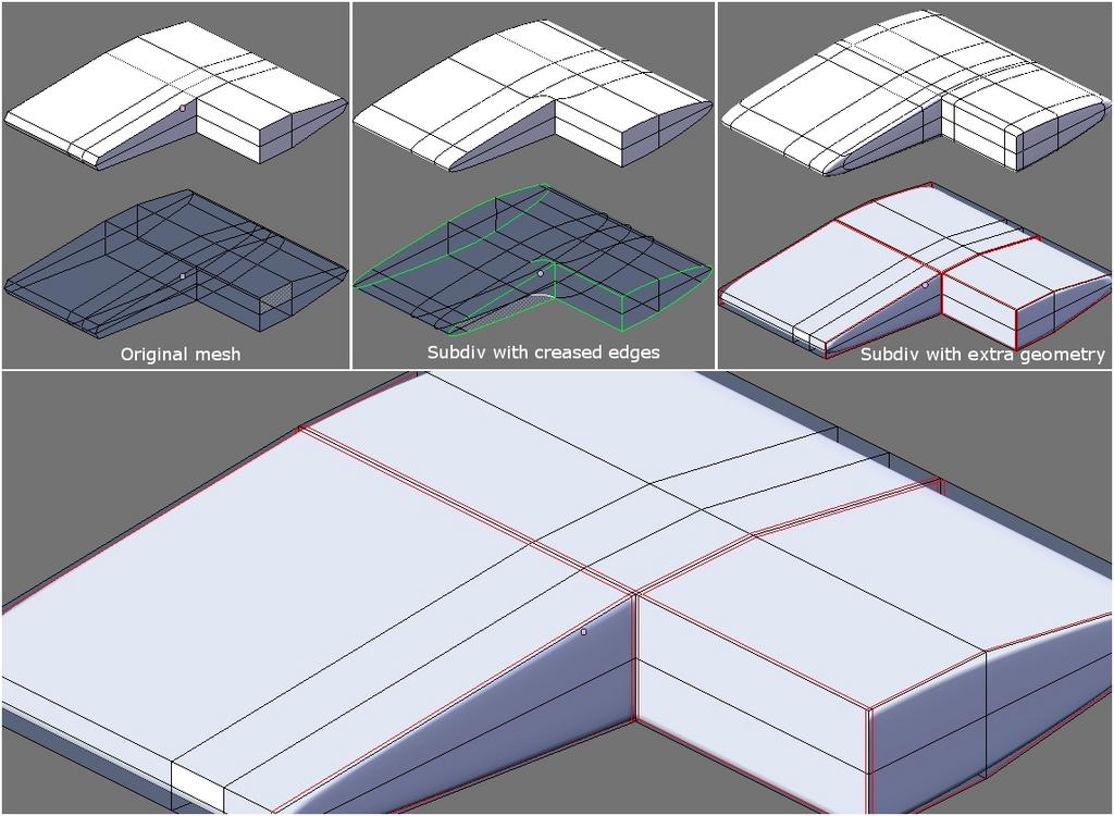
If I understand correctly you are trying to make sharp edges and corners to the wing.
When using subdivision surfaces there are two ways for doing that - edge creasing and adding extra geometry.
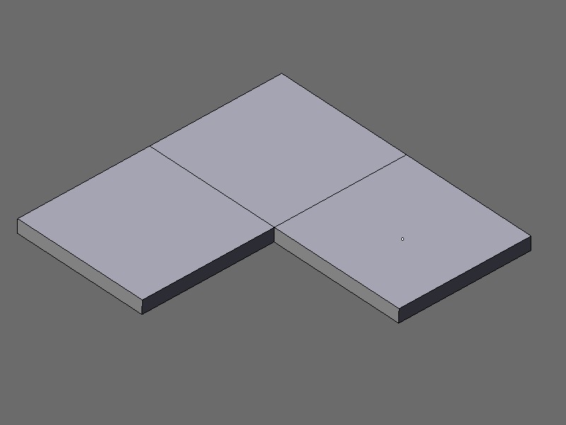
On the image below are the results from both methods. Variant 1 : with green lines are the edges from the original mesh that have been creased to value of 1. Variant 2 : with red lines are marked the additional edgeloops that have been added.
The bottom part is a close up of the Variant 2.
Both methods have their pluses and drawbacks - you have to choose which method is best suited for your needs.
Sorry if my explanation wasn’t clear enough, but you are correct in assuming what I am trying to do. Your diagrams look very clear and clean - thanks for going to that trouble to illustrate your points, I appreciate that time being spent !
I have posted a few here, all from almost exactly the same position, looking to where the aileron has been cut out of the wing.
Top left is where all the edges I’d like have been set with weight = 1. With subsurf it looks ok
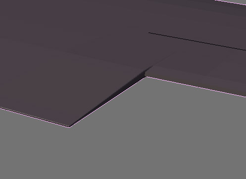
Top right is when smooth is used with edge weights set to 1.000, and in edit mode. As you can see the surface is moved around considerably by smooth
Upper middle left is the same shot but in object mode - the movement is more obvious here.
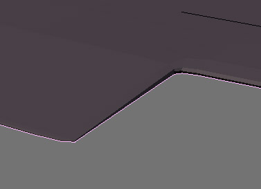
Below this, in Lower Middle Left I have added some extra edgeloops to control things. In lower right the same shot can be seen in object mode - you can see there is a slight problem with the ridge from the cutaway edge going forward over the wing.
Lower middle left has smooth turned on and again it seems to distort more than I’d like to see.
As I can see from your screenshots you are trying to achieve the effect by adding only one edgeloop to the sharp edge but you always need to have three to have true control over the sharpness. Sometimes this doesen’t work and the only thing I have found as a workaround is to actually separate the mesh into different pieces.
Thanks Musk. When you say I need to have three edgeloops, do you mean adding two (one either side I assume) to the existing edgeloop, or did you mean I need to add three more ?
You would have your ‘primary’ edgeloop, or ‘key’ loop, and then add one loop on either side, VERY close. The close they are, the tighter the subsurf will be.
Don’t forget your friend the slide edge feature. (ctrl-e, edge slide)
Hi all, thanks for all the suggestions. Hobo Joe and wizofboz, I think you are both suggesting the same thing (If I understand correctly), and that certainly seems to help. I can’t help thinking though that the model is a bit, well, unbalanced, as this method seems to create a lot of very very long thin quads. I’m not sure if that is a problem for other things, but it seems to perhaps be… not very elegant ?
Syziph, I have attached a cut down version of the blend file - I’ve removed all the rest of the model as originally it was too big to attach here. After deleting everything I found the compress file option which seems to have reduced the size a bit. If you need a version with more of the model let me know, but this has these pesky upper wings.
KevJon has suggested to me that I model the whole wing, ailerons included and then convert to high poly mesh and then do the cut outs. I’ll give this a try too (the more methods I try the more I’ll learn !) as it seems as it if might allow the mesh to look a little more regular.
Thanks for reading this far, and if you want to try with my blend file thanks even more. I have added in a number of “vertical” edge loops at key spots - the aileron cut-away, and all points on the trailing edge (thin rear part) of the wing - it certainly helps prevent the smooth modifier cutting too many corners. Cheers,
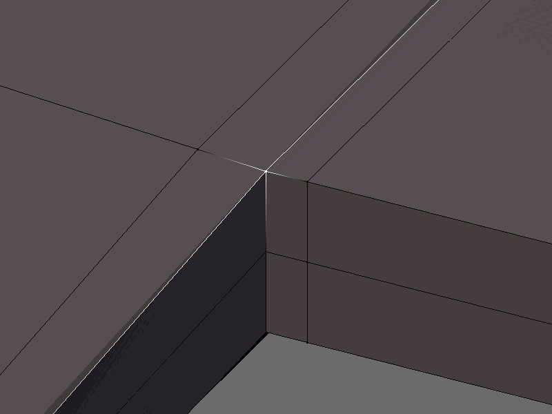
There are five edges coming into this point, and this is bad. Any point with more than four edges connected to it is called a pole, and should be avoided in subsurf modeling. So I changed this area around to look more like this:
In addition I saw some wonky topology in your file towards the tip of the wing. I suggest an edgeloop flow goes around the tip and looks something like this:
All of the suggestions I illustrated above I incorporated into a dummy mesh that I created above yours in your blend file, my modified blend is attached below. This is just a suggestion for how you might fix some problems in your original mesh.
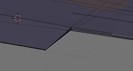
You do have 2 double vertices at the outer side of the wing. (Just do a W - Remove Doubles) and I would also suggest to make a quad face (even though it wouldn’t really be necessary), like in the pic I took. I am also not quite sure, why you do need the smooth modifier. Is subsurf not enough ?
I am also not quite sure if you would like to align the vertices a bit more even on the z-axis ?
Hello WolfOfBadenoch!
I am posting two modified versions of the wing.
The first one uses extra geometry to sharpen the edges.
The second one uses only edge creasing.
I’ve made some optimisation of the wing geometry but it is better to revise the overall topology and to find a simpler way of modeling.
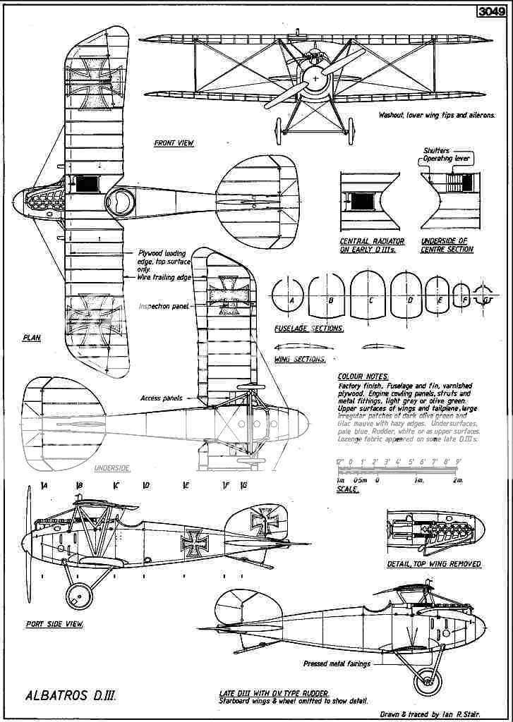
You can post the reference you’re using and someone may come up with better idea for constructing it in 3D.
Posting images and blend files incrases the chances of finding the solution
My goodness, I wasn’t expecting that people would go to so much trouble - thank you all very much.
Wizofboz : I see what you mean about the 5 edges - I think that came about as I extruded the wing out from the fuselage, and then scaled the trailing edge in towards the front, to form the back edge of the cut out. It obviously created some problems. How did you fix this - did you edit my file (how ?), or created a new one from scratch. Your edge topology certainly looks a lot cleaner than mine !
Tokka : Thanks for drawing that to my attention. I suspect it is a function of how I am trying to fix problems with the mesh. I’ve remove doubles a number of times (but clearly one time less than necessary). Trying to align vertices on that back aileron cut out has driven me nearly mad. What I’d like to do is just draw a line along the back edge, and then tell it to move the vertices along one axis until it hits the line - I think most CAD packages can do this, but I haven’t worked out a way to do this in Blender yet.
Syziph : Thanks very much for those two files - you really make my efforts look overcomplicated. Yours have an elegant simplicity to them. Would you mind describing how you turned my mesh into your versions - I’d like to repeat the process on my mesh if possible - I’ll learn a lot more that way.
I can’t remember exactly where I found the blueprint online, however I have it here at photobucket. If I’m somehow screwed up the permissions, please let me know and I’ll see if I can figure it out.
Once again, thank you all for your time and help so far.
Next, select the edgeloops one by one (with alt-rightclick) I show here (including underneath the model, there are three in all), and delete them (x, edgeloop).
I hope that was clear from just pictures, if not I’ll do a better job of explaining it.
Note that the above procedure creates geometry problems elsewhere in your existing mesh because of non-optimal topology, I was just illustrating what I did to fix the pole topology issue.
I also have another tip for you. Your wing has an arced profile to it, and I find that if I try to model this type of shape directly I end up with a mesh that’s hard to edit afterward (like your original mesh). I find it easier to model these areas “flat,” with verts and loops lined up with each other as much as possible, and then create the curved aspect later with a deformation modifier like a curve deform or a lattice. Then, when the geometry of the mesh is fixed and no further editing is needed, the modifier can be applied and the mesh attached to the rest of your model.
I have attached a blend file with the dummy object I previously made, but with a lattice deforming the mesh to roughly the shape of your wing.
Wizofboz : the explanation made everything very simple. I’m not sure how long it would have taken me to work that out without the explanation, and the pictures made it so easy to follow. The blend file is a treasure - I’m certainly going to be working through things with that Lattice modifier (another one that I had only ever scraped the surface with). As for your idea about modelling it flat to start with - it seems so obvious once you had mentioned it !
Syziph : Thank you for those links. It looks like there is lot of reading in there. I haven’t finished them yet, but already I think I know a lot lot more about poles than I did from my reading tonight. Your file is also great and I’ve learned a lot from it as well. Certainly a lot higher up the ‘elegance’ scale than my efforts to date.
Tokka : Sorry I missed your question about needing the smooth as well as the subsurf. Short answer, I probably don’t understand either of them well enough to give an informed answer, but had seen both used together previously on a quite a few models.:spin:
Thank you all for your assistance with this question. I’ll go off now and practice these new (to me) techniques and hopefully improve that model quite a bit ! :eyebrowlift:
Hi, you must feel practically overwhelmed by now, but in a good way.
I decided to do like Syziph and make a proper model of the wing to illustrate how I would do it (everything I showed you so far was just crummy rough sketching). I just used Syziph’s blend file and added my model to layer 2 (hope you don’t mind, Syziph).
This model illustrates one final point I want to make: I find it helpful to make an edgeloop inset evenly off any corners of a mesh, this helps control the subsurf crease at the corner all the way around no matter what deformations you do to the mesh later. Look at my wing mesh in top view to see what I mean.