RickyBlender - thank you!
However, to properly interpret these details, first I have to learn more about subsequent “Cyclone” versions (to not mix elements from various engines into a non-existent one). I will write more about it in the next post.
In this post I will finish all the remaining details on the front of the R-1820 engine. (As I mentioned in earlier posts, this model is intended for the outdoor scenes, with closed cowlings. That’s why I recreated the more complex rear part in a simplified form, just to check if it fits properly to the airframe).
One of the most exposed “Cyclone” details is the variable-pitch propeller governor:
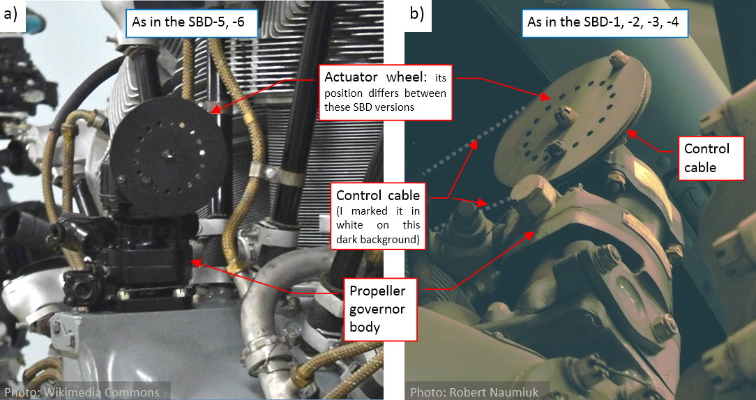
This is an additional unit that controls the pitch of the Hamilton-Standard propeller. (It controls the oil pressure, which determines the actual pitch of the propeller blades). You can find it in every aircraft, but it is often dismounted from the “standalone” engines, presented in the museums. The large wheel at its top is used as an actuator attachment. The actuator can be a pushrod or a cable from the cockpit. In the case of the SBD (and many other WWII aircraft) it was a control cable (Figure “b”, above). The engine depicted in Figure “a”, above is a standalone museum exposition, thus it lacks such a cable.
Analyzing the photos, I slowly recognized that this governor was mounted differently in various Dauntless versions. In the later SBDs (SBD-5, -6) it is placed in the front of the topmost cylinder, and its actuator wheel is on the left side (as in Figure “a”, above). In the earlier versions (SBD-1, -2, -3, -4) it is mounted between cylinder 1 and 2 (as in Figure “b”, above). Let’s focus on the later versions first, because I have more its photos. I could even find the propeller governor base on one of the original installation drawings (Figure “a”, below):
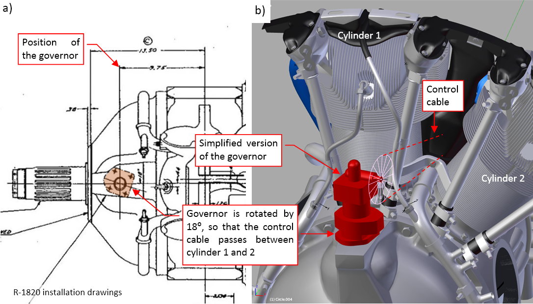
This drawing shows, that the governor was rotated by 18⁰. The reason for this unusual arrangement became obvious when I fit into the model the first, simplified version of this object. This rotation directs the control cables between cylinders 1 and 2 (Figure “b”, above). Do you remember the two small holes in the deflector depicted on the second-last photo from the previous post? They were made just for this cable.
However, I could not determine the ultimate shape of the governor unit. Most of the photos that I had looked like those that I show in the first picture of this post. They were taken at unusual angles, or the object was in black, which obscured its details. I was only able to determine, that there are several versions of this part, which differ in important features (for example, they have different number of outlets). It seems that this is a third-party component, delivered by independent vendors. In desperation, I looked for it on the e-bay, where I ultimately found a decent photos:
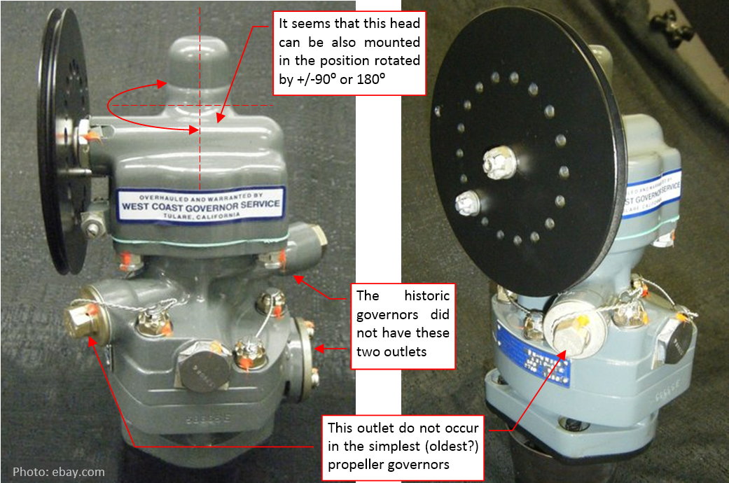
The version on the pictures above was widely used in the aircraft from the post-war period. It has two additional outlets, which did not exist in the propeller governors used during WWII (at least not on the photos that I have). Anyway, it still resembles the governors that you can find on the historical pictures. Using it, I was able to build a more detailed model:
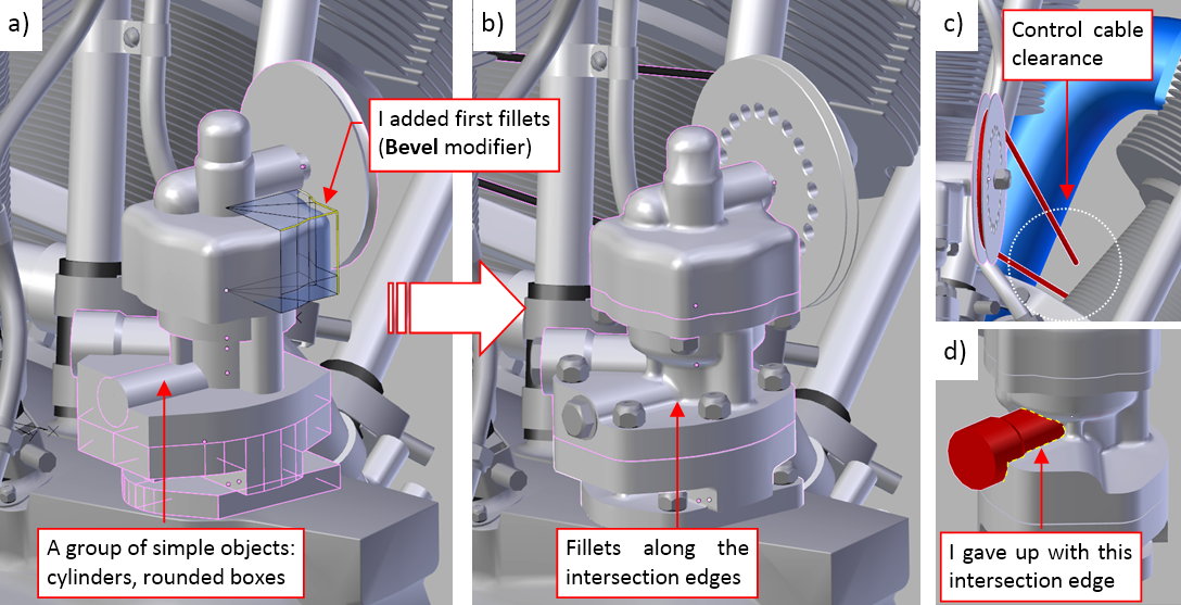
First I recreated the governor shape using a group of simple “blocks”: cylinders and boxes with cylindrical sections. Then I adjusted their proportions and positions, so that they resemble the original object. Finally I started to join these objects (using Boolean (Union) operator), and rounding their intersection edges using a multi-segment Bevel (Weight) modifier (Figure “a”, above). I set up a large “nominal” radius of this Bevel modifier (1.3”). Then I controlled the radii of individual fillets by assigned fractional bevel weights to their intersection edges.
I practiced that you can set these fractional values in the Mean Bevel Weight field of the Edge Data section, at the top of the View>Properties region. (The region at the right edge of the 3D View window that Blender shows/hides when you press the [N] key).
You can see the final result in Figure “b”, above. Note that I had to check the control cable clearance behind the deflector (it has to pass by the intake pipe of the cylinder 2 – as in Figure “c”, above). However, the fillets in Blender are far from the ideal: I gave up with the edge of the rear outlet (Figure “d”, above). To not spoil the previously rounded edges, I had to leave this cylinder as a separate object, just attached to the main body by the “parent” relation. (Fortunately, this is a less visible detail).
To round this edge, I should sculpt it in a mesh that is “dense” enough (i.e. has enough faces in this area). Such a labor-intensive solution does not match the level of detail assumed for this model.
The next detail is the elevated edge around the valve timing inspection hole. You can see it on the front crankcase section (Figure “a”, below):
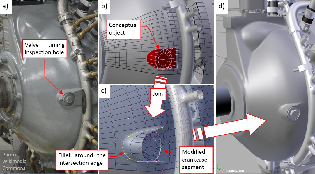
As usual, I started with a simplified, conceptual object (Figure “b”, above). It allowed me to adjust the proportions and size of this feature, as well as the mesh topology. Then I joined it with the corresponding crankcase segment, and rounded the newly created intersection edge with a multi-segment Bevel (Weight) modifier (Figure “c”, above). You can see the final result in (Figure “d”, above).
Finally, it is time to populate this engine with all nine cylinders. I delayed this operation to the end, because I was going to duplicate these objects as the clones (i.e. new objects that share the same mesh). After such a multiplication, if I discovered that these cylinders lack a certain detail, I would have to copy it nine times. That’s why it was better to wait with such a multiplication until it seemed that none of such modifications is needed. However, in May I received an invaluable suggestion from Jeff (pzzs7f, in this post) that I should try the so-called group instances. I did it in following way:
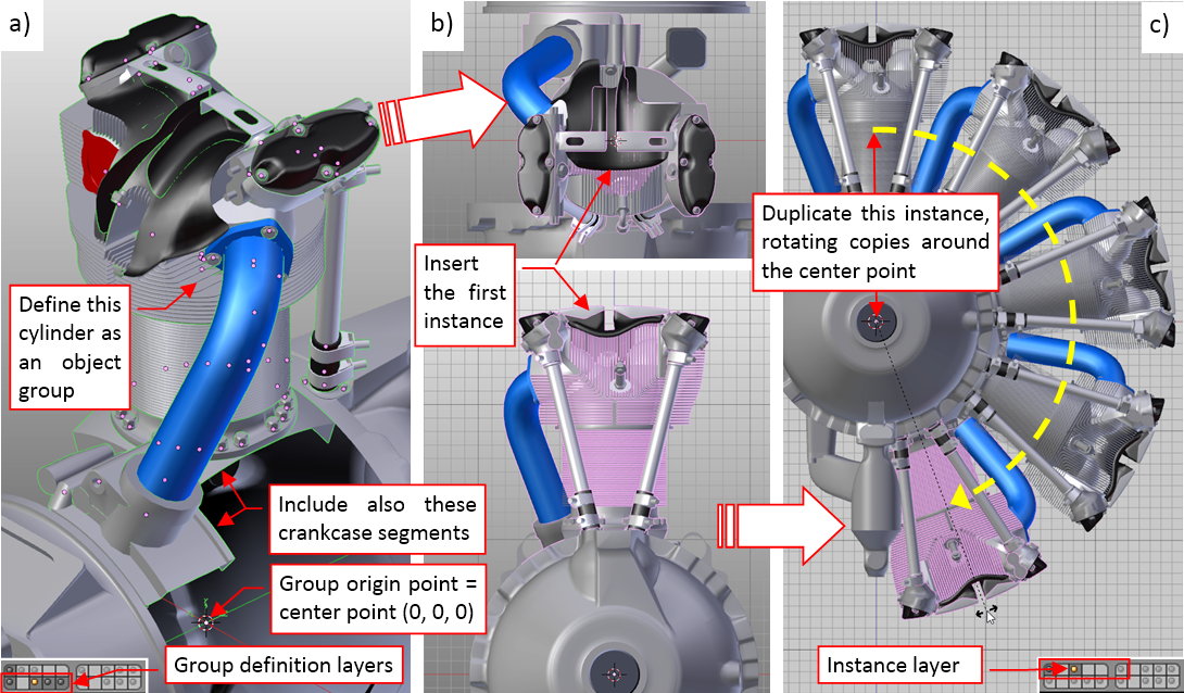
First I placed all the cylinder elements on layers 13, 14, 15, then declared them as an object group (Figure “a”, above). (I did it using the Object>Group>Create New Group command. Blender highlights the objects that belong to the same group with a green outline, which you can see on this picture). I named this group G.G05.Cylinder. Note that it also contains the crankcase segments located around the cylinder (elements from layer 11). Beware that Blender assumes the center point ([0, 0, 0] in the global coordinate system) is the eventual origin point of an object group. Thus place your source objects accordingly in the space around this point.
When this “group definition” was ready, I turned its source layers off, set the 3D cursor to the engine center point, and in the top view I inserted the first instance of this group (Add>Group Instance). You can see it in Figure “b”, above. (Accidentally, it is located in the same place in the space as the source objects, but you could insert it anywhere). When you examine this cylinder, you will discover that this is an Empty object, which contains reference to the G.G05.Cylinder object group.
To “populate” this engine, just create clones of this first instance, and rotate them around the center point by 40⁰, 80⁰, 120⁰, and further angles. You are placing in this way the subsequent cylinders in their locations (and rebuilding the mid- and rear-crankcase, as well). Figure “c”, above, shows how it looks like. Note that I have placed all these cylinder instances on a different layer: 3.
Such instances of an object group are a great tool in dealing with repeatable machine parts. When you add an additional object to this group, it immediately appears in all cylinders. When you remove an object from this group – it disappears from all instances (although it still exists on one of the source layers). This means that I could use these instances earlier, without worrying about adding the remaining details! Well, in my next model I will recreate the cylinders at least in the middle of the project. It is always better to see the whole engine.
What’s more, Blender optimizes the way it displays and renders such instances: note that its Faces/Verts/Tris counters do not take into account their meshes!
Figure “a”, below, shows all nine cylinders in place. Note, that each of them contains also the spark plugs. After this “multiplication”, I carefully examined each of these group instances, looking for eventual intersections with other objects:
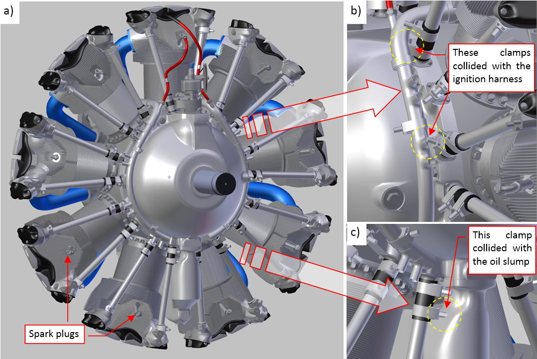
As you can see in Figures “b”, “c”, above, there are just few of such collisions, caused by the clamps on the pushrod seals. I have tried to rotate these clamps, hoping to find a universal “neutral” position that does not collide with anything. Finally I gave up: I excluded clamps from the object group and copied their clones around the engine. Then I could rotate each of them separately around the pushrod, fixing every collision that I had found.
I also recreated the side deflector as another instance group:
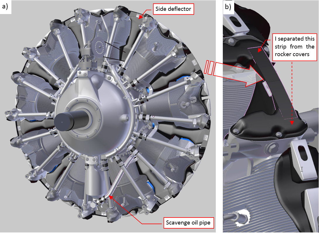
I named this group G.G10.Deflector. Its source objects are located on layer 16, while the group instances – on layer 6. At this moment all the deflectors are identical (for example, they were mounted in this way in the “Cyclones” used in the B-17s). For such an effect I could simply add the side deflector into the cylinder group (as I did for the cylinder top deflector). However, in the SBDs there were two gun troughs in the cowling, on both sides of the topmost cylinder. Thus I decided to define this deflector as another group, because in the future I will have to replace the two topmost deflector instances with modified clones. For the same reasons I “extracted” the side beam from the rocker cover into a separate object (Figure “b”, above).
Looking at Figure “a”, above, you can find some additional parts: a few dozens of new bolts, as well as the scavenge oil pipe. (This pipe connects the bottom of the oil slump with the pump in the rear).
Finally I added the last remaining detail: spark plug cables:
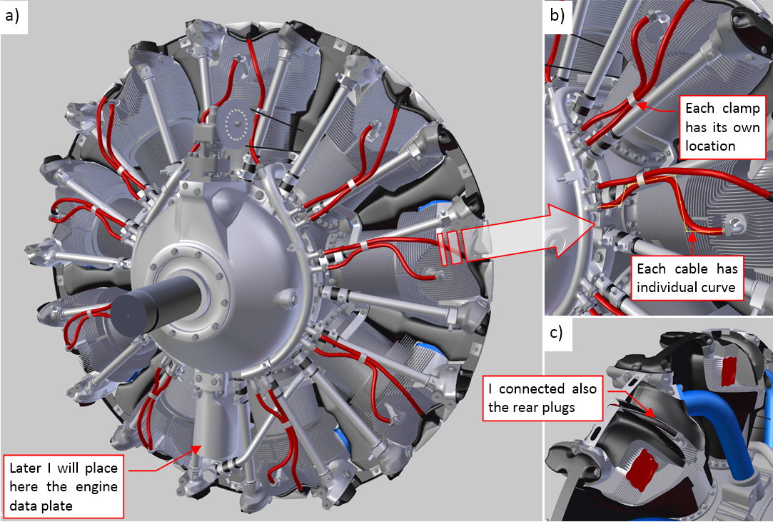
As you can see, the cables occur in pairs. In each pair there is a longer and a shorter cable. The longer one connects the rear spark plug (Figure “c”, above). (I know that this is the “invisible” area, but I could not resist the temptation to recreate this detail). The shorter one connects the front spark plug (Figure “b”, above). All cables of the same length (short or long) and their terminating nuts share the same mesh (they are clones). However, each of them has its own shape, because their Curve Deform modifiers refer to their individual curves (Figure “b”, above). I copied these curves around the crankcase, and then introduced minor modifications to their shapes. Also the clamps that attach these cables to the pushrods are individual clones. I introduced some random variations to these shaping curves and the positions of the cable clamps that attaches them to the pushrods. In this way they resemble the original, manually connected cables. The only missing element in this model are the engine data plates. I will recreate them later, together with the cockpit details. (They require a dedicated, high-resolution texture).
The engine seems to be complete. (Of course, for the assumed level of details: the rear crankcase sections and their equipment are recreated in the form of simplified blocks). I will fit it into the cowling, then cut out the deflectors below the gun troughs.
I zoomed the data plate on one of my reference photos, and found that this is the R-1820-60 (the version used in the SBD-5: 1200hp for takeoff). All the manuals and blueprints that I have collected describe this or one of the later “Cyclone” versions. Thus I can conclude that the R-1820-66 (the version used in the SBD-6: 1350hp for takeoff) seems to be identical (at least as viewed from the front).
I also expected just minor differences between this one and the earlier R-1820 versions, used in the SBD-1, -2, -3, -4. The first difference that I have found was in the propeller governor positions (at the beginning of this article). Then I started to analyze the other older photos:
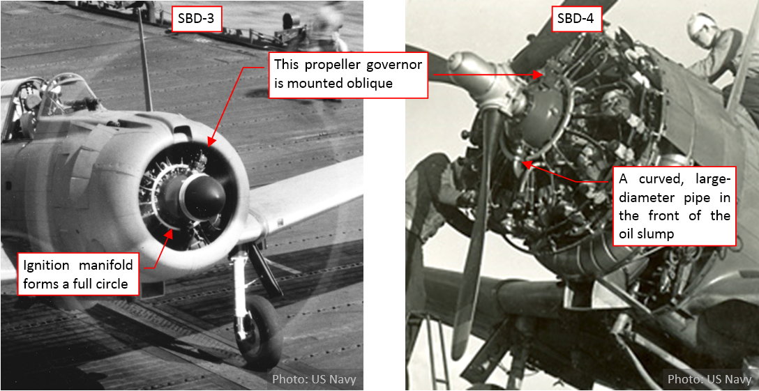
I quickly found another one: in the R-1820-52 the ignition manifold forms a full circle, while in the R-1820-60 it is a 300⁰, “U-shaped” arc). I decided to look closer at the differences between the R-1820-52 and -60. I will report my findings in the next post.
You can download the model presented in this post (as in second-last figure in this post) from this source *.blend file. It is available under CC-BY license and can be useful for other aircraft, for example the B-17 or the F4F-4.