To recapitulate my work on the Dauntless plans, I decided to draw all the external differences between its subsequent Navy versions. Because of the numerous changes that occurred in the SBD-5, I decided to split this description into two posts. This is the part one describing changes from the SBD-1 to SBD-4. The part two (about the SBD-5 and SBD-6) will be ready in the next week.
NOTE: All airplanes on the drawings below are equipped with the small tailwheel with solid rubber tire for the carrier operations. However, for ground airfields Douglas provided alternate, pneumatic, two times larger wheel. These tail wheels could be easily replaced in workshops.
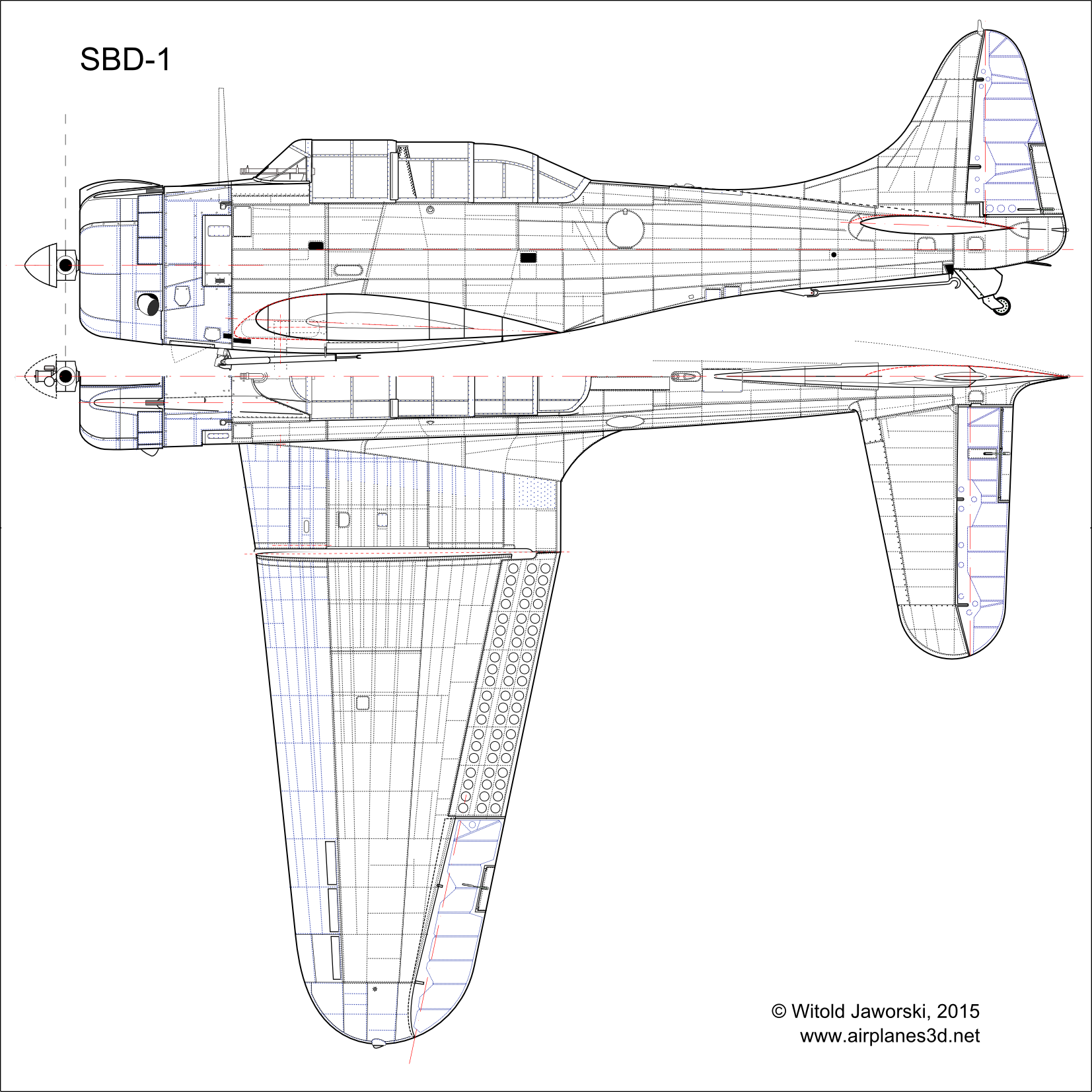
Starting from the beginning: here is the SBD-1, the first of the Douglas Dauntless series:
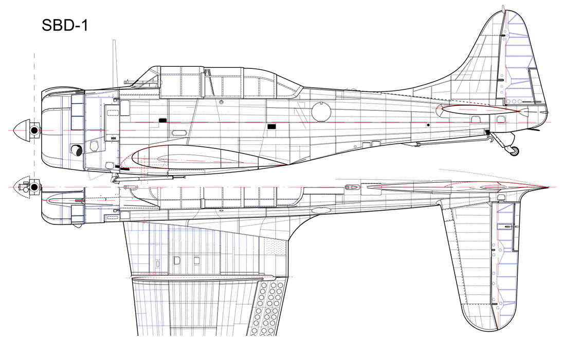
(See the high-resolution SBD-1 left & top view).
US Navy originally ordered 144 SBD-1s in March 1939. The first of these aircraft took off from Douglas airfield in May 1939. However, the Navy was not satisfied with their relatively short combat radius. Probably the outbreak of the war in Europe (September 1939) forced the Navy to accept first 57 SBD-1s “as they were”, assigning them to the Marines squadrons. For the 87 remaining airplanes from the original contract, the Navy requested longer range. To improve Dauntless combat radius, Douglas installed additional fuel tanks in the external wing panels. They also equipped these airplanes with the Sperry autopilots. This new variant was named SBD-2. It was delivered in 1940 to carrier squadrons of the US Navy. Externally, the SBD-2 had lower carburetor air scoop than the SBD-1:
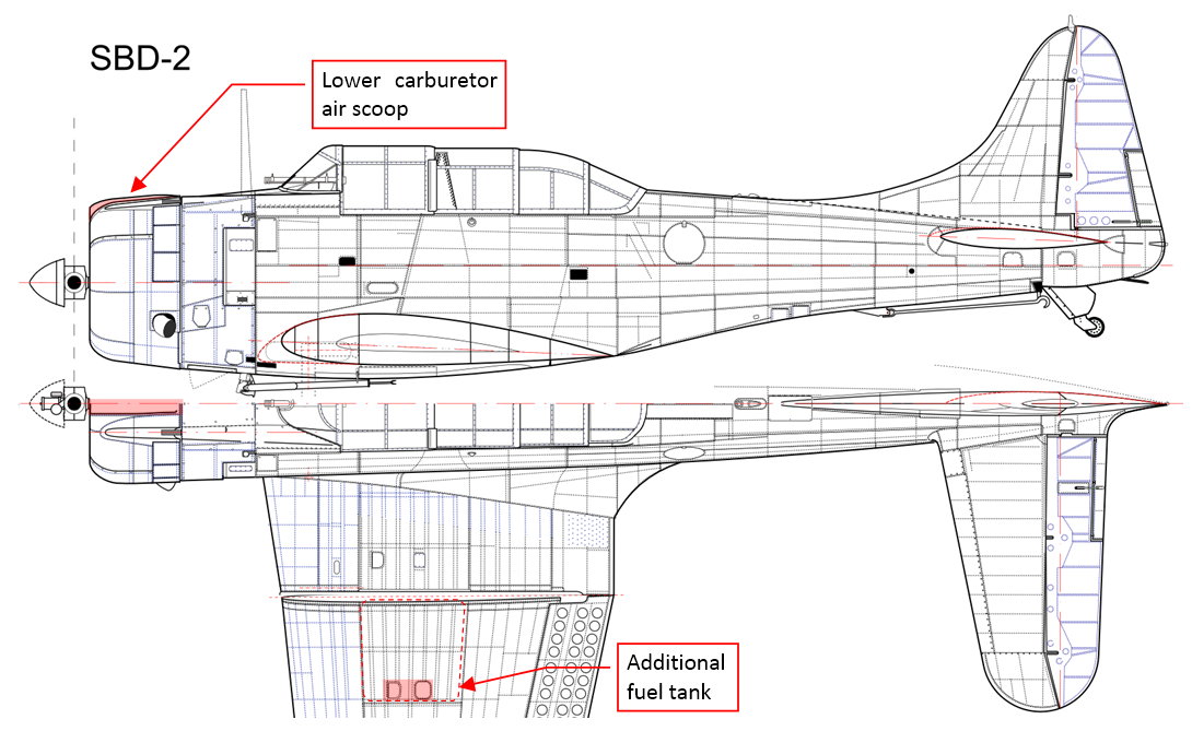
(See the high-resolution SBD-2 left & top view).
The next Dauntless version — the SBD-3 — was originally ordered in 1940 by French Aeronavale. SBD-3 was updated for the identified requirements of contemporary battlefield. It had armor plates protecting pilot and gunner seats, armor glass plate inside the windshield (I did not draw this and other cockpit internal details). Douglas installed also the self-sealing fuel tanks. After June 1940 all 174 ordered aircraft were taken over by the US Navy, which then ordered additional 411 airplanes. The Navy workshops doubled in these machines their rear guns. This modification was adopted by Douglas in the later series of this aircraft. Externally — the boxes containing flotation gear (“balloons”) were removed from the engine compartment:
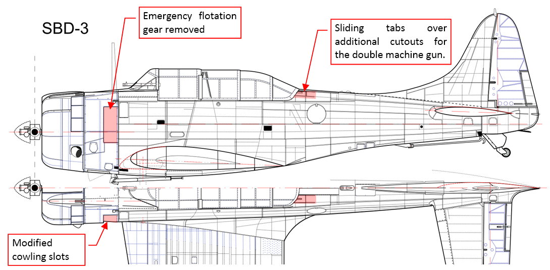
(See the high-resolution SBD-3 left & top view).
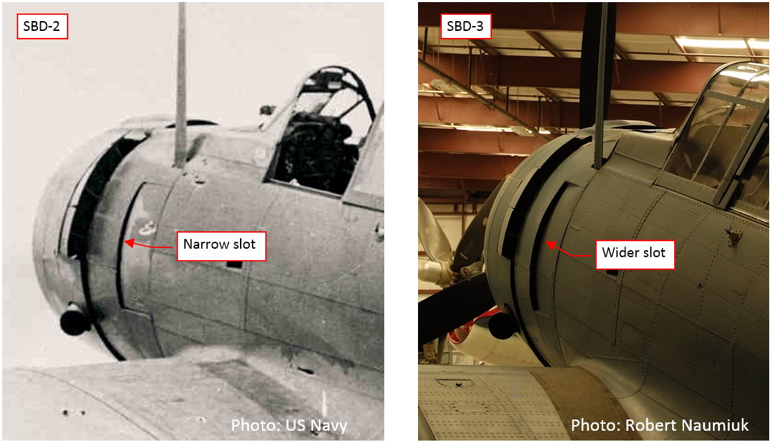
The side slots of the SBD-3 cowling were slightly larger than those in the SBD-1 and SBD-2:
The next version — SBD-4 — received new, 24V electric installation, which allowed for installment of the radar and broader range of other electronic equipment. However, in the 1942 the Navy was short of these devices, and the factory-fresh aircraft did not have any of them. (The Navy workshops installed radars on some SBD-4s later). Externally you can recognize this version by the new Hamilton Standard Hydromatic propeller:
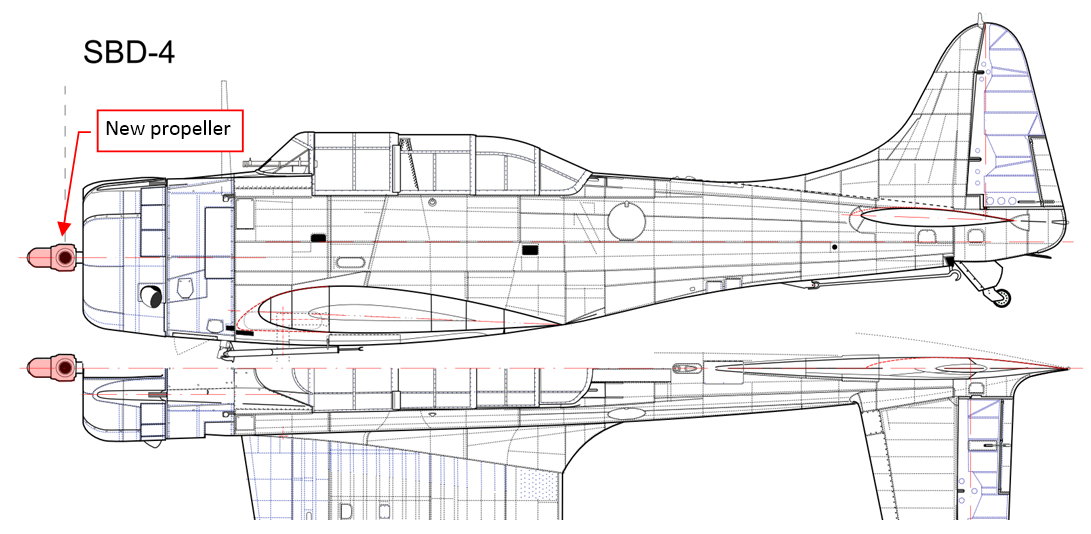
(See the high-resolution SBD-4 left & top view).
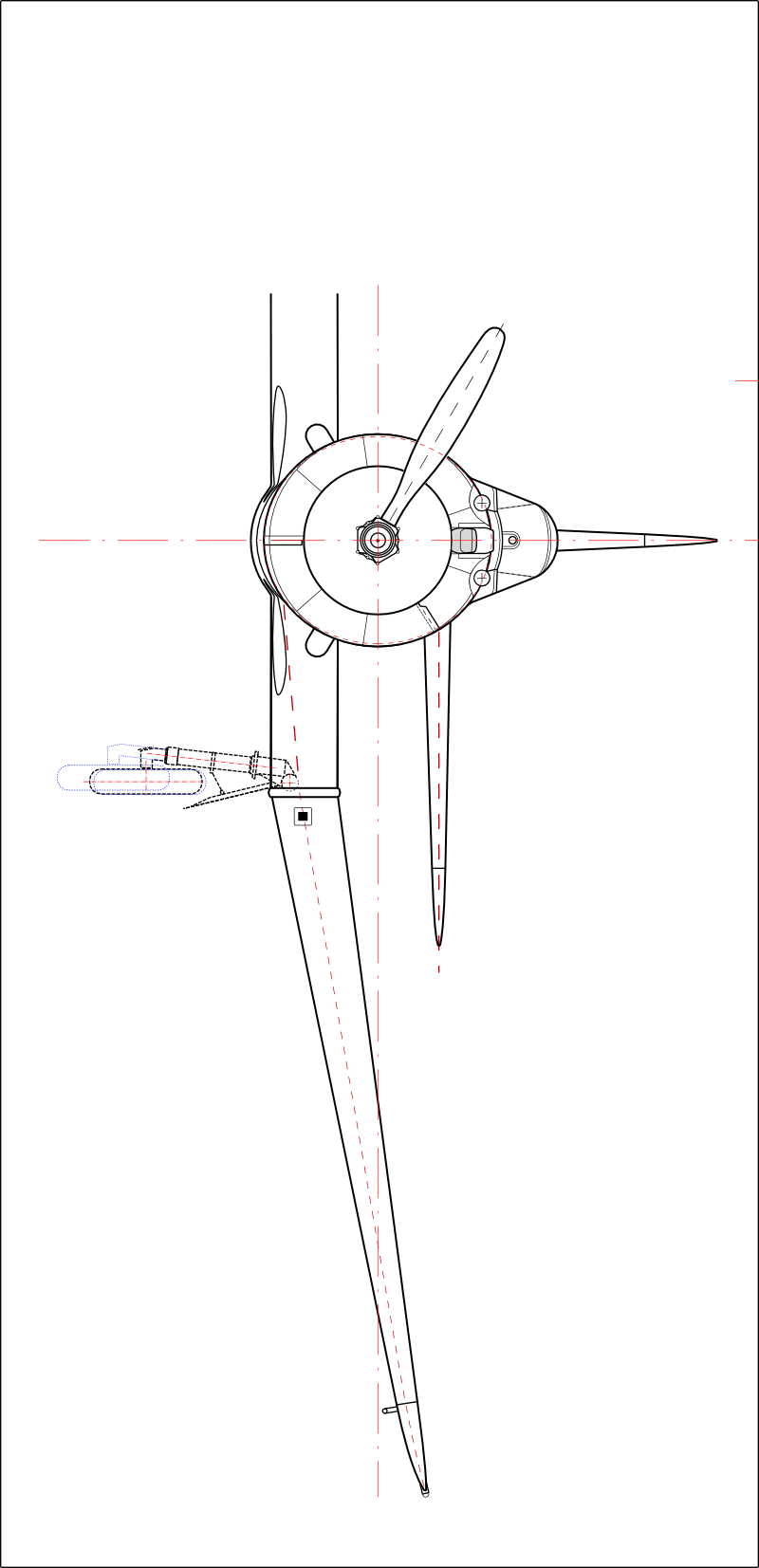
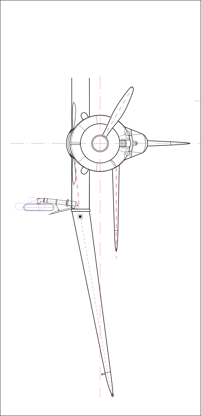
The previous SBD versions (-1, -2, -3) used the Hamilton Standard Automatic propeller. As you can see in drawing below, the blades of these propellers had different shapes:
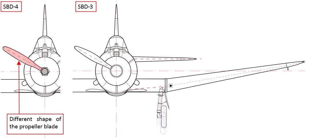
(See the high-resolution SBD-4 front view, SBD-3 front view).
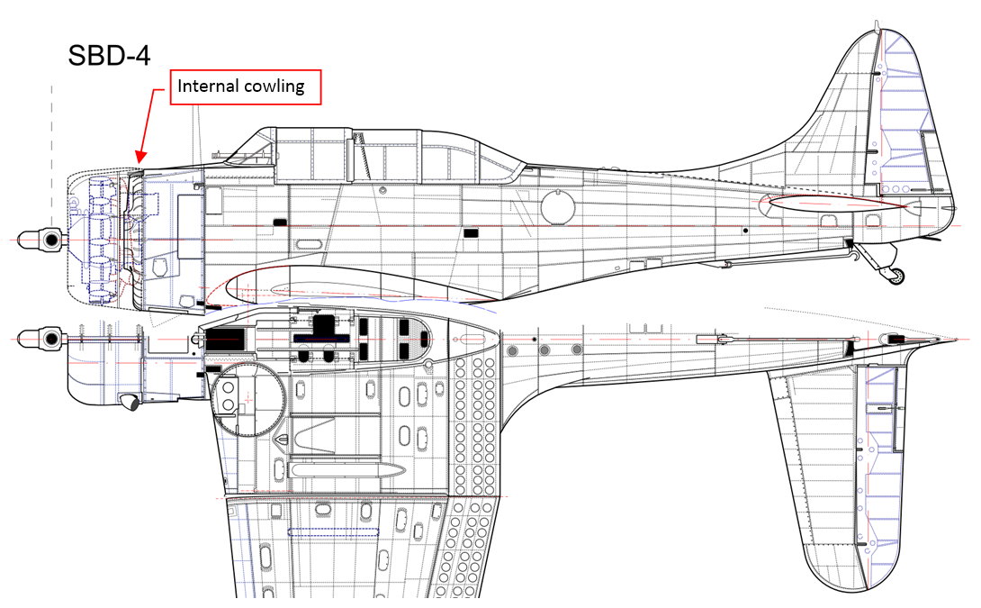
Below you can see another drawing of the SBD-4, consisting the bottom view as well as the side view without the NACA cowling:
(See the high-resolution SBD-4 bottom view).
Comparing it to similar drawing of the SBD-5 published in the previous post, note the different profile of the internal cowling (the cowling behind the engine cylinders). For this version I had no photo of its upper part! The shape of this element is deduced from the shape of similar part in the SBD-5 and from the size and location of the Stromberg-Bendix injection carburetor, located just behind this cowling.
Next week I will describe the external differences between SBD-4 and SBD-5. It will be the last post about the “general” reference drawings. Then I will report my progress on the first element of this model: the wing.