Your attention to detail is mind boggling. If you can keep up this amount of perfectionism until the end of the project the final renders will be spectacular.
Greetings from Germany,
Fast
Your attention to detail is mind boggling. If you can keep up this amount of perfectionism until the end of the project the final renders will be spectacular.
Greetings from Germany,
Fast
Very nice.
A shit loada work isn’t it? 
Here is my plane I am working on lets print them out in 3D and have a dog fight!
http://worldofclouds.com/efmsmedia.html
… and I thought I was crazy about detail …
Anything less than “perfect” is not the Witold way…
I bought his books to do my airplane some time ago - it is mind boggling how much better a model looks if you follow this man’s methods. :yes:
Keep up the good work Witold…
Cheers, Clock. ![]()
Oh I’m not knocking his work or his determination to do the best he can. It’s great to watch, and I’m picking up all sorts of useful tips along the way.
Gumboots, FastLeaD, etiennea, clockmender - thank you!
@Gumboots - indeed, I have to finish at least the all external details to the end of this year. (I am going to use this model for making the scale plans and color profiles for a 56-pages monograph, that I promised to a modelers’ bimonthly magazine…);
@clockmender - I am very happy that you have found these books useful!
@etiennea - nice model of the the Catalina! The huge amount of work on the details is clearly visible - and it greatly enhances the final effect.[SUB] [SUP]I can see that you have “cut” the panel lines in the mesh. There is an alternate way: keep this mesh simpler, and recreate these panel lines as the bump (or normal) texture. I fill the panels with linear gray gradients, to obtain the effect of overlapped sheet metal. I think that it is much easier, and the final effect looks (at least in Cycles) more realistic. If it is not too late, I would also suggest to correct the wing airfoil shape: it had smaller leading edge radius and more convex middle section (you can see it on the photos, here is also an old drawing).[/SUP][/SUB]
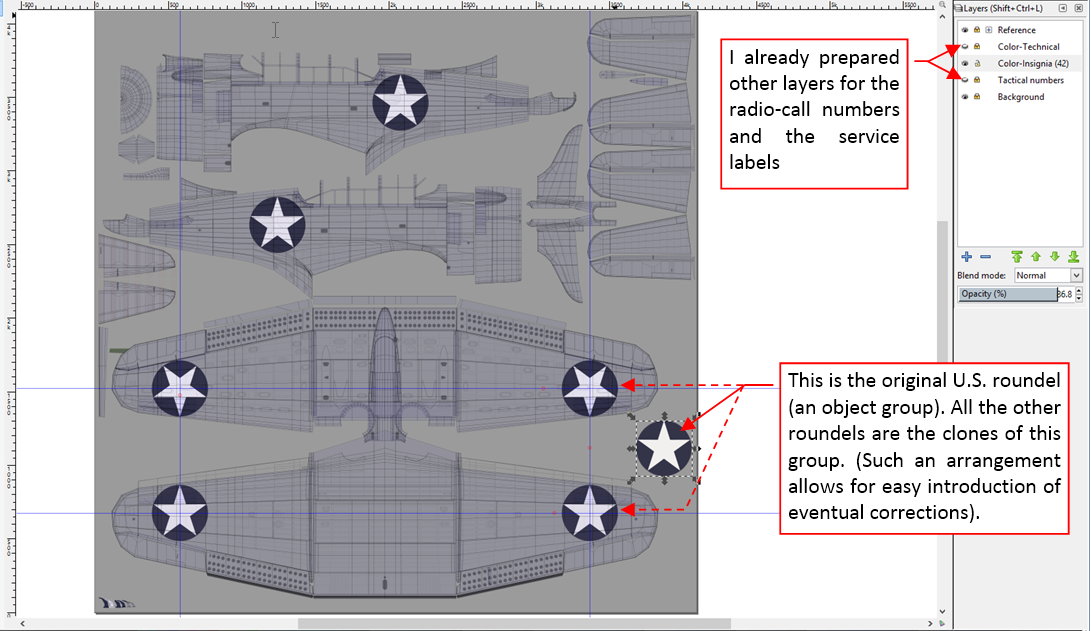
The last texture for my model contains various elements that in the plastic kits are delivered as the decals: national insignia, radio-call numbers and various service labels. I prepared it as another vector drawing in Inkscape:
I exported this picture to a raster file named color-decals.png. It has transparent background, because I will combined this image with the other components of the color texture, prepared in previous posts.
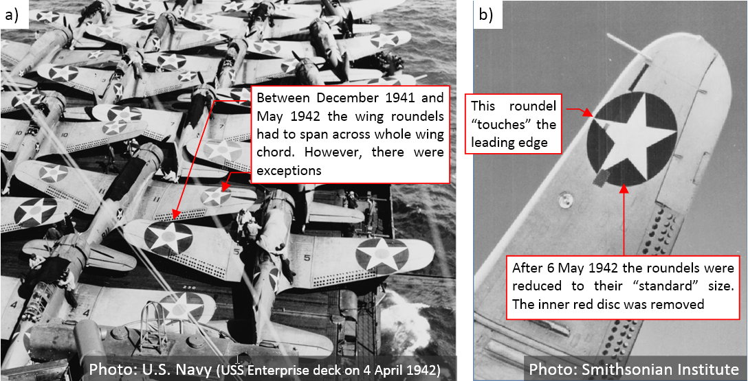
The U.S. national insignia passed various transformations during the WWII. Between December 1941 and May 1942 the roundels on the Dauntless wings were enlarged, so they spanned over the ailerons (see figure “a”, below):
However, as you can see in the photo of the USS Enterprise deck, there were exceptions: some aircraft preserved the older, smaller roundels. After 6 May 1942 all the roundels reverted to their “standard” size (72 in). Note that in this case they did not “touch” the aileron, but still their outer edge was very close to the leading edge (as in figure “b”, above).
All of this means, that I cannot use for these wing roundels the same UV map as for the camouflage (UVMap). Although in this default UV layout the ailerons are in-line with the main wing surface (so they also fitted for the “decals” image), the problem occurs on the leading edge. In the UVMap layout its seam runs on the wing bottom surface, along the edge of the first panel. (I masked this seam on the camouflage texture in this way). Such a layout would split the bottom roundel into two parts – as marked in Figure “a”, below):
To keep these roundels “in one piece”, I had to create another copy of the default UV layout (UVMap). I named it UVDecals. Then I modified it, adding an additional seam along the leading edge, and shifting appropriate faces from the upper to the bottom surface (as in figure “b”, above).
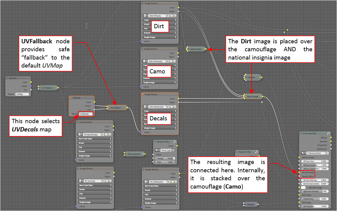
In fact, I created this new UV layout only for the two objects: the outer wing meshes. This is possible in Cycles thanks to a special “fallback” node. In my previous model I worked out a node group, which can deliver the default (UVMap) coordinates for the all meshes that do not contain the requested (UVDecals) map. Such a group greatly simplifies using alternate UV layouts. You can find it in the material scheme as the UVFallback node:
Conceptually the color (diffuse) texture is composed from three images. The Decals image is placed over the camouflage (Camo), while the Dirt image is placed over them. Technically, the X.Textured Skin node internally places the decals image over the camouflage. Thus in the scheme you can see the Dirt image placed over the Camo and Decals images (it uses two Stack Image nodes for this purpose). If you want to learn more about these group nodes, see vol. III of the “Virtual Airplane” guide).
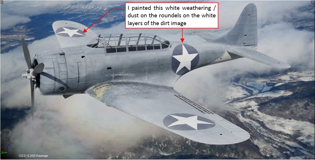
In the GIMP source, I shifted all the Stains layers from the color-camo.jpg into the color-dirt.png (see Figure 76-5 in this post). It allowed me to use the white stains layer for recreating weathering on the roundels located on the upper wing surfaces.
The stars on the wing bottom surface were also painted inside the letterbox slat. Initially there was something wrong with my UV mapping of this element (figure “a”, below):
The pictures of the star on the slat inner surfaces were distorted (shifted). To fix this issue, I copied current UV layout (UVMap) into the UVDecals layout, and then shifted some of its inner UV vertices (figure “b”, above).
Below you can see the first test of the “decals” texture:
At this moment it only contains the national insignia.
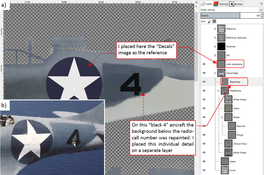
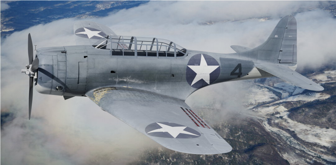
Now it is the time to “personalize” this aircraft. Let’s recreate the “black 4” from VSMB-241. As the first thing I added the radio-call numbers:
The single-digit number (“4”) was painted using the standard stencil. There was no problem in recreating this detail using the USAAF stencil font. (In fact – its vertical “stroke” was shortened. To recreate such a shape, I transformed the text into path and made appropriate modification). Then I exported from Inkscape the resulting color-decals.png picture and placed it as the reference in the source GIMP image, above the Camouflage layers. Finally I painted the darker background behind the radio-call number on a separate layer, as a new part of the camouflage image.
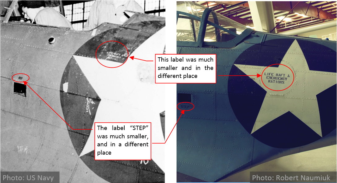
Using the USAAF font I am able to quickly recreate various service labels. In fact, most of them disappeared from this war-weary “black 4”. On the archival photo I can see only one label, on the life raft door (above left horizontal arm of the star – see figure “b”, above). It is interesting to note how this detail appears on the restored aircraft:
As you can see, the labels on the restored aircraft are too large, and located in the wrong places. I recreated these elements in Inkscape, on a separate layer.
Restored aircraft can differ from the original in many details. In particular, their painting (the hue and the gloss of the camouflage, service labels fonts and sizes) leave much to be desired.
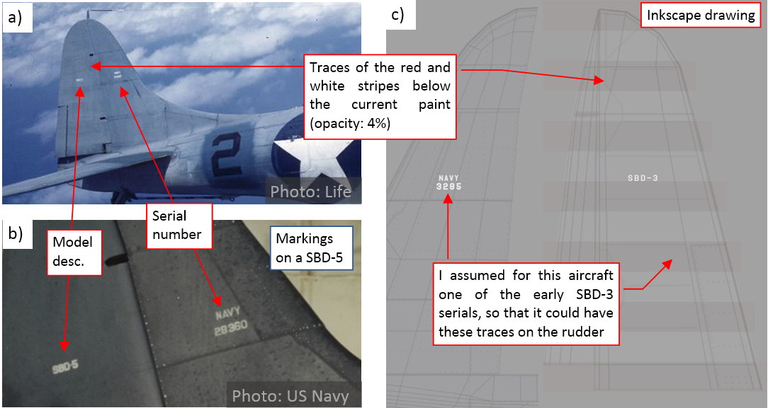
The last elements that I have to draw my “decals” texture are: the serial number (on the fin) and the model description (on the rudder). Unfortunately, the serial number is too small to be readable on the reference image, and the rudder is clipped out of its photo frame. All we can do is to use the photo of another aircraft from the same flight (as in figure “a” below):
Among the historical photos, I had only close shots of these numbers on some SBD-5s (figure “b”, above). They showed me the proper font and size of these labels. For this aircraft I could only use a random serial number (figure “c”, above). I chose one of the lesser ones from the two polls of the SBD-3 serial numbers (3185-3384 and 6492-6701). I suppose that the aircraft from this first pool were delivered before December 1941. On the historical photo (figure “a”, above) of another aircraft from VSMB-241 you can still see the traces of the red and white stripes on the rudder, painted in December 1941. Then, in May 1942, the rudders were covered with the standard camouflage. You still can see these stripes behind the Blue Gray paint, because it was impossible to scratch the previous paint from their fabric skin. I reproduced this effect on my “decals” texture, drawing seven highly transparent stripes on the rudder.
Below you can see the final render of the “black 4”:
I also prepared for this model an alternate, sea environment:
I think that this picture of the Pacific Ocean creates a more familiar surroundings for such a naval aircraft. You can find the definition of this environment in the World tab of my Blender file. I named it Sea. Consequently, I renamed the previous environment to Land. You can easily switch between these two “worlds”.
In the next post I will work on the three-color Navy camouflage, used after January 1943 (you can find it mainly on the SBD-4s and SBD-5s). I will re-use in that new color scheme most elements from this two-color painting (the dirt texture, some of its weathering). Thus it will be a much quicker work.
In this source *.blend file you can evaluate yourself the current version of the model, and here are theInkscape and GIMP source files of its textures. [SUB]Because of the large size of the original GIMP file (.xcf), this post is accompanied by its smaller version (2048x2048px), packed into .zip file. I think that such a version is sufficient for checking all the details of this image (the structure of its layers, their opacities and mixing functions). The resulting textures (4096x4096) are packed into accompanying Blender file.[/SUB]
I am speechless.
thorst: thank you for following :)! Today I am discussing another case: the tri-color Navy camouflage: ________________________________________________________________
In my previous post I finished the case of so-called “two-color” U.S. Navy camouflage, which was used between September 1941 and January 1943. You can observe on the archival photos that its non-specular Sea Gray / Light Gray combination was especially prone to weathering, and accumulated every grain of the soot and drop of the oil stains. Simultaneously the weathered Sea Gray paint became more and more white. The new, “tri-color” camouflage, introduced in January 1943, fixed these flaws, and provided better protection on the vast, dark waters of the Pacific. You can see an example of this pattern on an SBD-5 from VB-16:
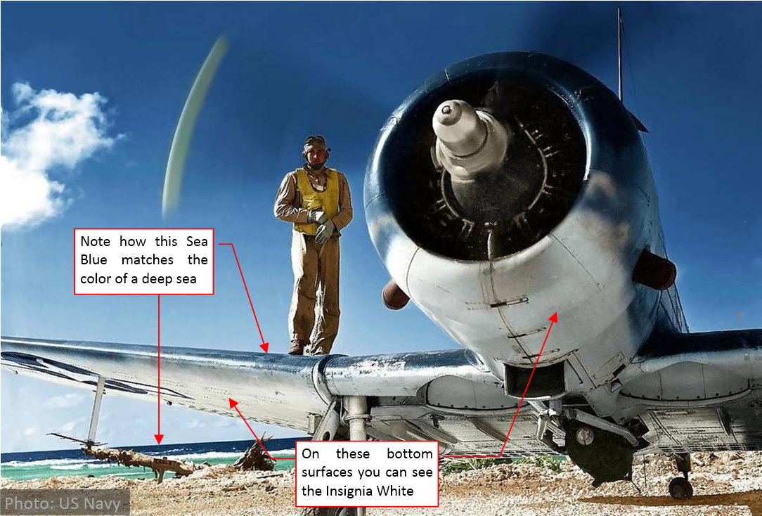
However, this historical photo has a technical flaw: its colors are “shifted toward blue”. You can unmistakably see this “shift” in the color of the bottom surface (it was Intermediate White). I was not able to correct this deviation, finding acceptable. Below you can see another photo of a SBD-5 from VSMB-231, which colors are more balanced:
There were two variations of the tri-color painting scheme. While the most probably the “white 35” from the first picture represents the painting applied in the factory, the photo below shows a case of another variation:
The main difference is the dark Sea Blue section below the cockpit. It is creating a “bridge” of the Sea Blue color between the upper areas of the wing and fuselage. Most probably such a camouflage was applied by the Navy workshops, when the older aircraft were repainted from the “two-color” scheme. Note that all of the SBD-5s on this photo have larger national insignia than the “white 35” from the first picture. Their stars have precisely the same size and location as those in the two-color scheme. (It seems that the workshops just painted the two rectangles on each side of an existing roundel). You can also encounter aircraft that had the “bridged” camouflage and the smaller (i.e. standard) insignia, but it seems that all aircraft without the “bridge” below the cockpit had the standard roundels. This fact seems to confirm the “workshop” hypothesis of the “bridged” camouflage origins. Many modelers think that this variant of the tri-color scheme was created in the main Navy overhaul facilities at Norfolk.
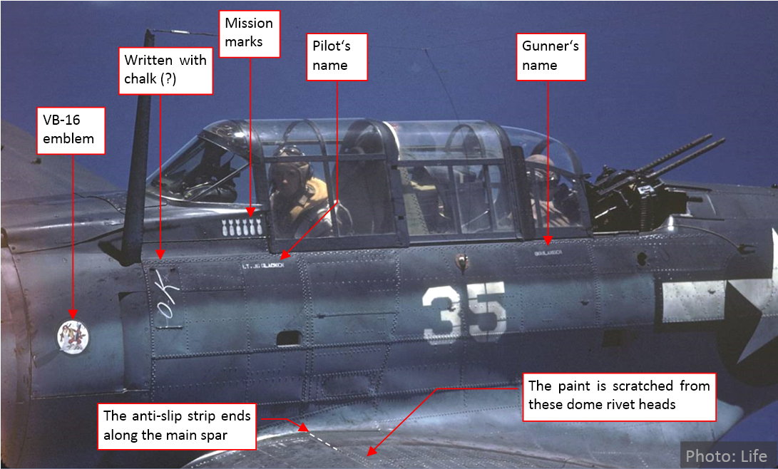
In this post I will recreate the “white 35” shown on the first picture. This particular aircraft belonged to VB-16 squadron from USS Lexington (CV-16), and was flown by Lt. (Jg) George T. Glacken, with RM Leo Boulanger at the rear gun. There is another close-up photo of this aircraft, most probably taken during the same flight (early April 1944, over New Guinea):
This SBD-5 seems to be n much better condition that the weary SBD-3 from my previous post. From the photos of the other VB-16 aircraft it seems that the crew of this squadron had enough time to take care of their machines. All of them had uniform squadron emblems, the flying staff names were painted below the cockpits, and every mission was marked with a small “bomb” on the fuselage.
Unlike on the SBD-3, on this SBD-5 the anti-slip strip ends at the main spar (there is no forward part, painted in the glossy black). There are no visible deep (“bare-metal”) scratches on the center wing upper surface. Just some irregular areas and a few seams of the dome rivets are brighter. Most probably the paint was scratched from the heads fo these rivets. (There is no such a thing in the front of the main spar, because its seams were made of the “flat”, countersunk rivets).
I started my work on this camouflage by creating a new copy of the previous source GIMP file (Color.xcf). Then I modified its contents by repainting some key layers. Finally I exported the resulting pictures, overwriting the existing images (texture components in the skin material of my model).
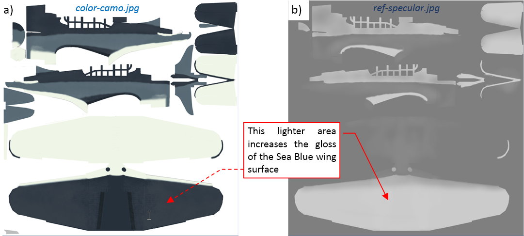
The first repainted elements were the basic layers of the camouflage (color-camo.jpg image) – as in figure “a”, below. This is one of the three color texture components. I simultaneously modified the ref-specular.jpg component of the reflectivity map, providing the “gloss” to the dark Sea Blue surfaces (figure “b”, below):
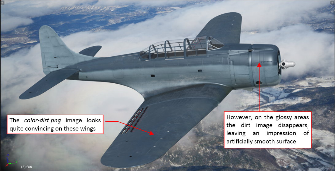
I left the weathering layers of the camouflage image intact (hey are the same as in my SBD-3). You can see the first test render of this new camouflage (combined with modified color-dirt.png image) below:
This first render revealed that while the non-gloss surfaces look quite convincing, I had an issue with the more glossy upper surfaces. The dirt pattern disappeared on the highlighted areas. They look unrealistic smooth and clean (like on a polished airliner!).
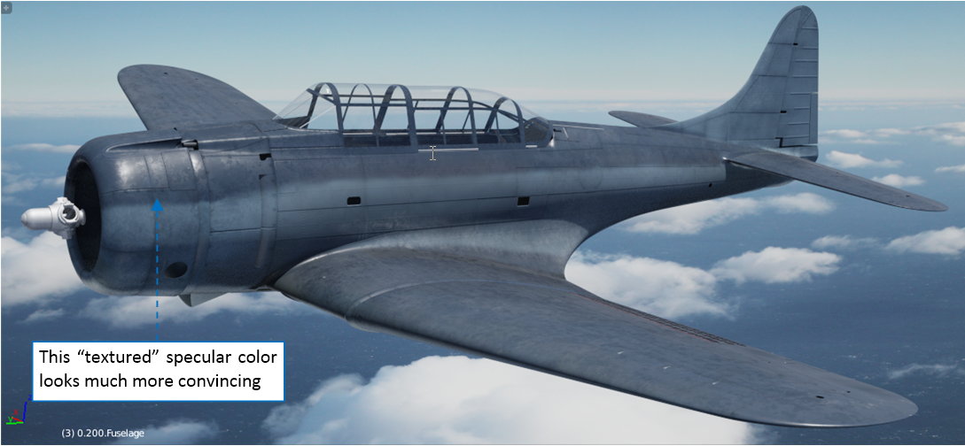
The remedy for this issue is yet another texture, which will “modulate” the color of the specular reflections, making some areas darker than the others. It is quite simple – a neutral gray background and just some darker splashes. I named it color-specular.jpg. Figure below shows this image and its place in the material schema:
I also could put these splashes on a white background. However, I did not know if I would need some lighter elements. That’s why I used a neutral gray here.
Figure below shows the test render of this updated material:
I reproduced the scratches on the center wing in the same way as in the two-color SBD-3: using the scratches mask (mask-scratches.jpg image):
In this case the only bare-metal spots are the heads of the dome rivets. I recreated them using an inverted copy of the reference image. I also added some partially scratched areas in the front of the anti-slip stripes (they “reach” just the primer color).
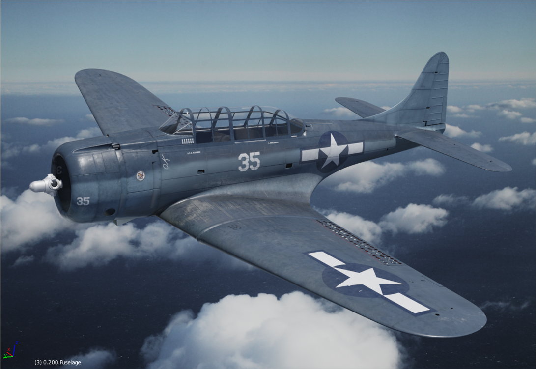
Finally I prepared the “decals” picture in Inkscape, then exported it to the color-decals.png file. Analyzing various photos of other aircraft from the same squadron, I determined that the serial number on the fin was black, and small radio-call numbers (“35”) were also painted on the wing upper surface. I repainted in GIMP the VB-16 emblem (it seems to be in the contemporary cartoon style). Then I exported to a *.png file, and placed it in the SVG source image as a linked picture:
Below you can see another test render, featuring the complete texture set:
In overall, the tri-color painting looks acceptable. However, this model badly needs the details: the cockpit interior, radial engine, crew… Thus, in this post I am finishing the third phase of this project (“working with textures and materials”). Now I am starting the last, fourth phase: detailing. For most of the small parts that I will create in this last phase, I will use simpler materials that do not require any UV-unwrapping and texture images. For example – on the picture above the propeller hub requires different material (in this “white 35” it seems to be painted in a glossy Sea Blue). At this moment I kept the hinges and canopy rails in the natural metal color. I will have to “repaint” them, using simpler versions of the camouflage colors. Finally, it seems that I have to improve the glass material of the cockpit canopies (comparing with the archival photos, they are too “clear”). Anyway, I will describe my solutions to all these issues in the future posts.
In this source *.blend file you can evaluate yourself the current version of the model, and here are theInkscape and GIMP source files of its textures. [SUB]Because of the large size of the original GIMP file (.xcf), this post is accompanied by its smaller version (2048x2048px), packed into .zip file. I think that such a version is sufficient for checking all the details of this image (the structure of its layers, their opacities and mixing functions). The resulting textures (4096x4096) are packed into accompanying Blender file.[/SUB]
Stunning. The last picture looks like an original photograph - only the missing details are giving it away. It will be a masterpiece.
Thank you for describing your workflow in such detail!
Thorsten
I am in awe of your fantastic skills and your attention to detail. This project is truly amazing! That last picture does look very close to an actual photograph, just slap on a filter and you could have fooled me (aside from the missing details). Keep up the good work, I look forward to seeing the final render
Your texturing job is top notch. Thank you for showing the how to, too.
thorst, JakeAnthony, MadeWithFeet: thank you for following this thread!
I published my previous post a month ago, but the current stage of this project – detailing – requires less frequent reports. (Otherwise the posts would become rather monotonous: week after week they would describe making similar things, using the same methods). I started this last phase of the Dauntless project by recreating its main landing gear. First, I had to finish it, then I am able to write about this process. Thus I will describe it in this and next two posts. (I will publish them in a short sequence, week after week).
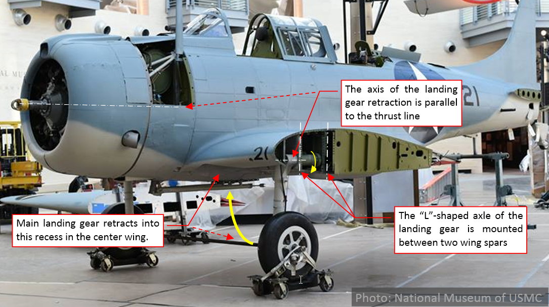
The retractable main landing gear of the SBD was probably a direct descendant of an experimental solution used in the Northrop 3A fighter prototype. In general, it looks quite simple:
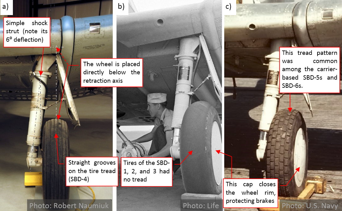
The upper part of the landing gear was an “L” – shaped tube, mounted between two wing spars. The lower part, visible below the wing, was a simple shock strut mounted to the wheel axle (see figure “a”, below). The axis of the landing gear retraction was parallel to the thrust line and perpendicular to the walls of the spars (see figure above). The shock strut is deflected (by 6⁰) from the vertical axis, so that in the open position the wheel is directly below the axis of landing gear retraction (see figure “a”, below):
Figure above also shows various treads of the SBD tires. The tires of the earlier versions (SBD-1, -2 and -3) had no tread pattern (figure “b”, above). The simple “straight grooves” treads appeared on the SBD-4 wheels (figure “a”, above), while in the SBD-5/6s we can find a more elaborate, “brick” (figure “c”, above) or “honeycomb” tread patterns.
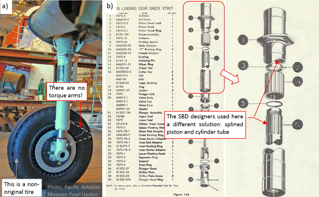
Another interesting thing is the lack of the torque arms, that connect the cylinder and piston of the shock strut in most of the other aircraft (figure “a”, below):
The SBD manual explains that the designers used splined cylinders and pistons in their shock strut (figure “b”, above). It looks like a quite elegant solution for the blocking random torsions of the shock strut piston (less outer parts that are prone to the eventual dust and jams). I did not find any complaints for this landing gear in the veteran memoirs and technical reports (usually they praise the “rugged structure” of the SBDs). However, all other aircraft designs use the torqe arms in their landing gear. Maybe they were just cheaper (i.e. easier to produce)?
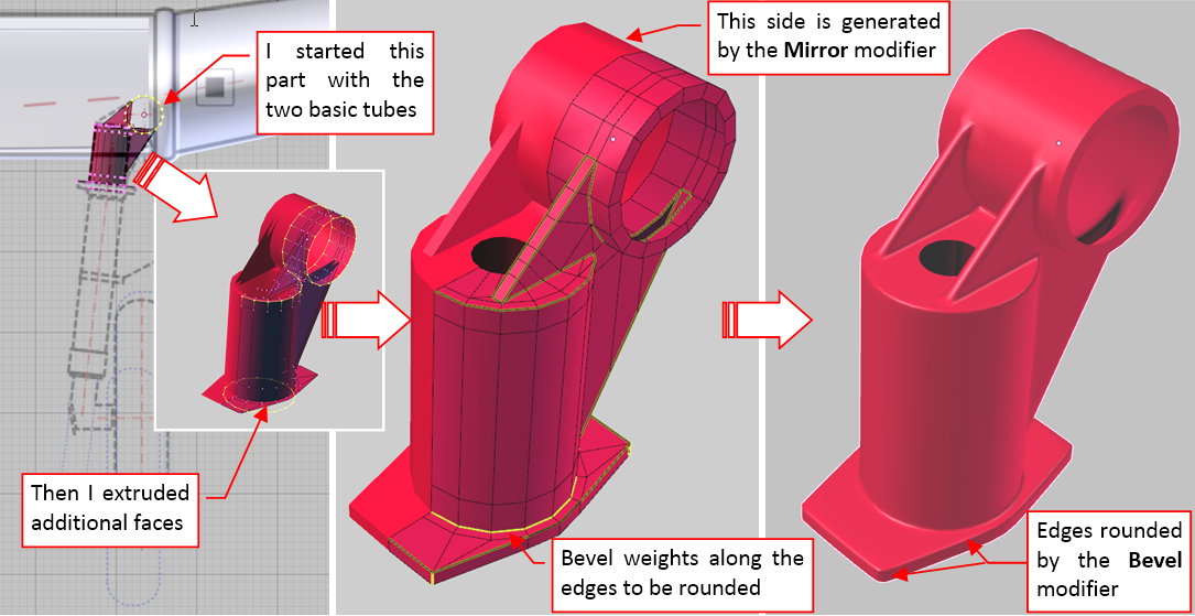
Basically the work on the details means that you have recreate “in the mesh” all the parts you can see on the photos. Below you can see how I recreated the upper part of the landing gear leg:
Recreation of such a die-cast part, with all of its additional walls, roundings, is a small challenge. To make it with as simple mesh as possible, I used several modifiers. First, I used the Mirror modifier to automatically generate the symmetric half of this object. (This symmetry was only possible because I decided to split this “L” – shaped part into two objects: this complex die-cast and a simple tube behind it. (This tube is not present in the picture above). Then I recreated all the rounded edges on this object using dynamically-generated fillets. Another modifier (Bevel) creates fillets along all the edges that I assigned a nonzero bevel weight. (The fillet radius is controlled by the value of this weight).
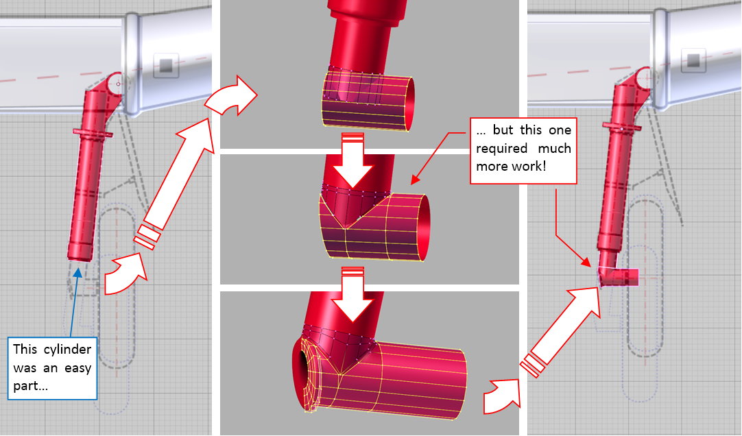
When this upper part of the landing gear leg was finished, I created the cylinder of the shock strut. It was just a tube with an octagonal flange *– nothing difficult. Then I had to create the lower part of the leg:
It was another die-cast, which shaping required some time. (As you can see in the figure above, I formed this mesh from two crossing tubes).
While creating such a detailed assembly, I prefer to model each of its parts as a separate object. It gives me the opportunity to take advantage of its local coordinate system, when I need it. For example – the shocking strut is a tube rotated by 6⁰. When I formed it, I often extruded its faces along this local axis. Another advantage of such a model structure is the possibility of quick, “natural” adjustments of various parts. (For example – piston movement along the cylinder. In my model it occurs along its local Y axis).
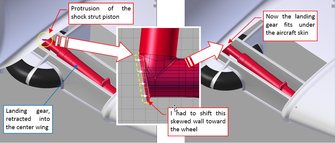
Building the landing gear, I tried to check its retracted position as early as possible. Figure below shows first of these trials:
As usual, a small fragment of the retracted landing gear leg protruded from the upper wing surface. I had to re-examine the photos, find which part has the wrong shape, and fix it.
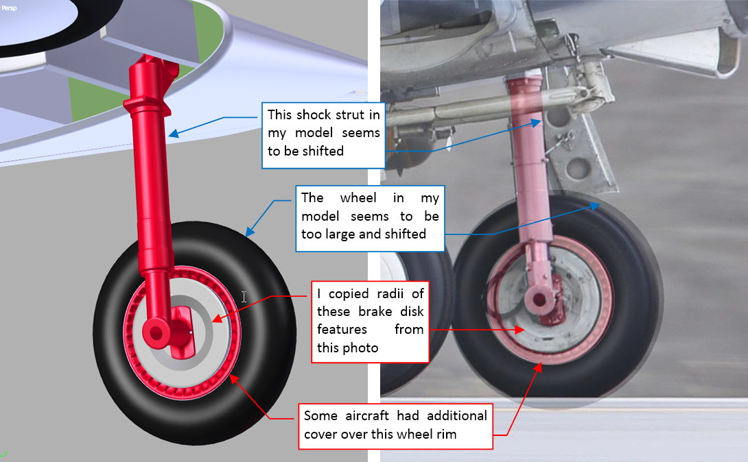
I also used my photo references to recreate other landing gear elements, like the wheel brake disks:
During this work I also found some differences between my model and the reference photo (see the notes in blue frames in the figure above). It seems that my landing gear is somewhat shifted forward.
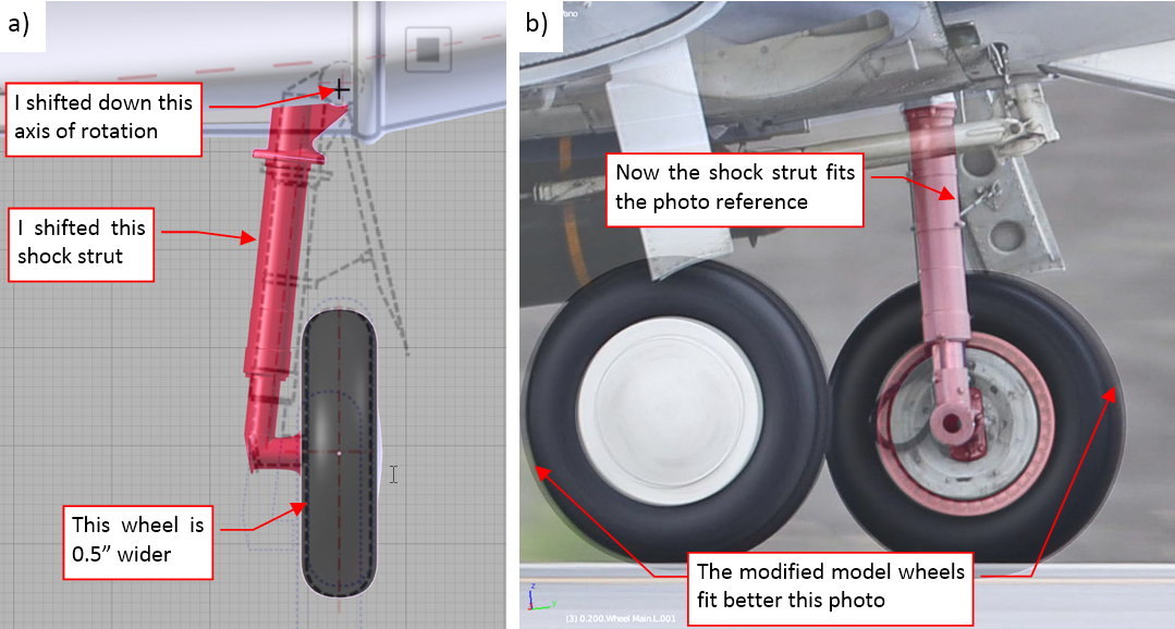
Such a finding led to many rearrangements in the geometry of this assembly:
In the background of figure “a”, above) you can see my original drawing from 2015. After some deliberations, I decided to leave the center of the wheels at its current location, because it was dimensioned on the original general arrangement drawing. However, after measuring tire proportions on various photo, I decided that the SBD used slightly wider tires (30x7.5”) than the size (30x7”) specified in one of the comments placed on the original drawing from the SBD manual. (Sometimes draughtsman could make such a mistake). To fit the photo, I adjusted location of the shock strut, moving it slightly toward the fuselage. I also shifted downward the axis of retraction (rotation). Figure “b”, above, shows how the updated model fits the reference photo. The tires on the photo still seems somewhat smaller than those from my model. However, I decided that this restored CAF aircraft could use a slightly smaller tires (29x7.5”). (This particular SBD-5 also uses at least another non-original part: a different version of its Hamilton Standard propeller).
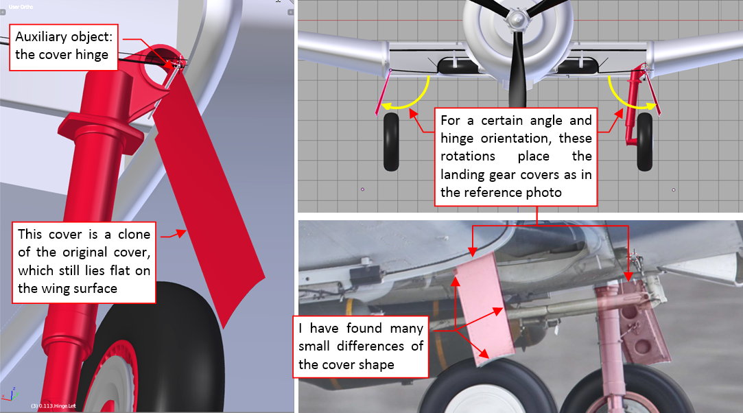
Another element that requires some adjustments are landing gear covers. Although I created them during the modeling phase, now I have to compare their shape with the reference photo. Preparing for this test, I placed in my model a simple “stick” which I use as the hinge (I set it as the parent of the landing gear cover):
The hard part was to determine the proper axis direction and the angle of this rotation. Surprisingly, the hinge was not lying directly on the aircraft skin (it would be the simplest solution). While it was relatively easy to find for a given hinge orientation a rotation which angle placed the left cover as on the photo, the same rotation applied to the right cover did not match the reference. It required some hours to find a combination that produced an acceptable (although not ideal!) match.
As you can see, I performed a lot of various checking, adjusting and matching while forming the key elements of the landing gear. All of this because it is still quite easy to correct the geometry of this assembly while it is relatively simple. It would be a nightmare, when I did such a thing on the final, detailed assembly, which you can see in figure below:
However, before I finished this landing gear in such a state depicted in the figure above, I had to create several dozen bolts of various size, as well as other details. I also discovered some small secrets of its retraction mechanism. You will find a short description of all of these findings in my next post (to be published next week).
I decided to not enclose the source Blender file to this post, because it would contain just these few basic landing gear components. I will add it to the next post, which describes this assembly in the finished state.
Beautiful work on the landing gear and wheel well.
I didn’t know you could weight edges for the bevel modifier, that’ll come in very handy for some modelling tasks, thanks for the tip !
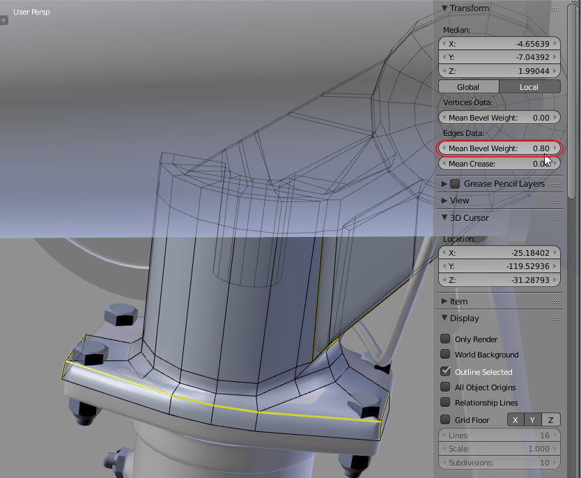
You are welcome! Because I didn’t mention this tip in my book, here are the details:
I assigned to the object a multi-segment Bevel modifier in the Weight mode. The bevel distance, set there, determines the maximum possible fillet radius (corresponding to bevel weight = 1.0).
In the Edit mode you can assign smaller bevel weights to selected edges, by altering the Mean Bevel Weight in the Properties:Transform panel:
Thanks Witold for the additional explanation. A very useful function to know !
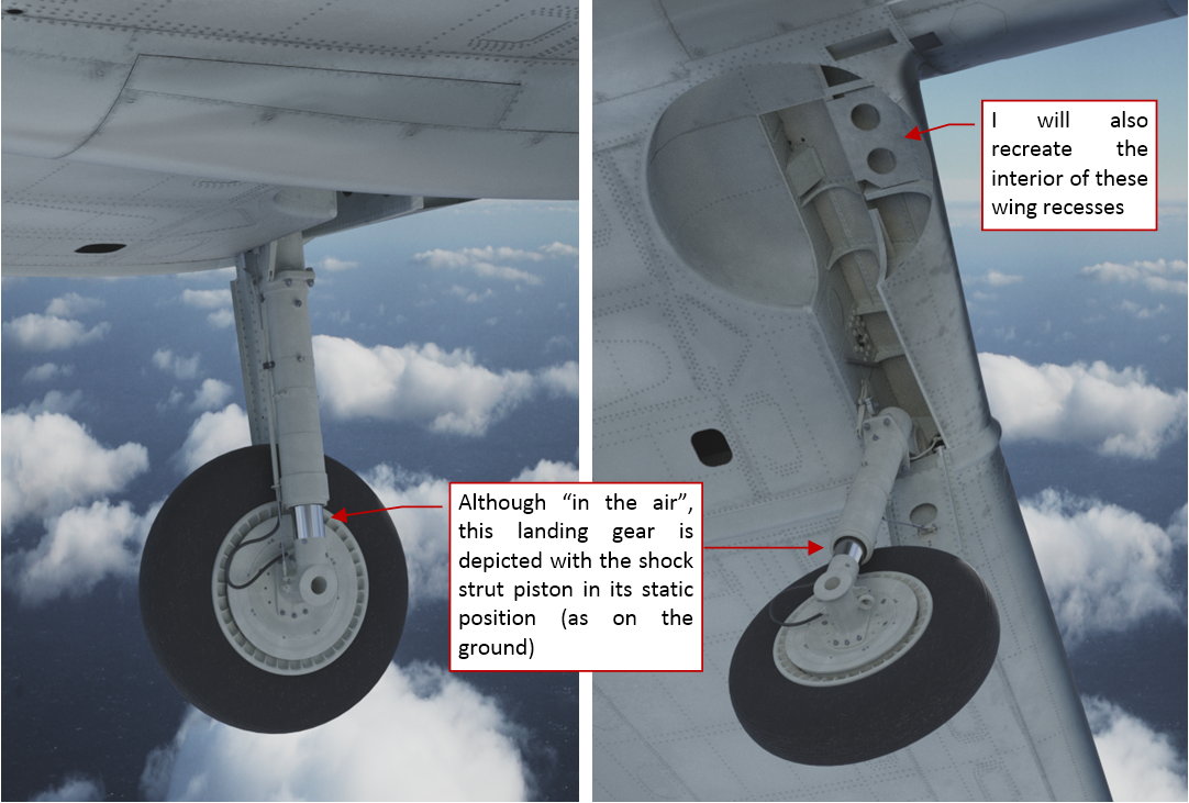
The SBD shock absorbers had to disperse a lot of the kinetic energy of landing aircraft, minimizing the chance that the airplane accidentally “bounce” back into the air. (This is a key requirement for the carrier-based planes). For such a characteristics you need a relatively long working span between the free (i.e. unloaded) and the completely compressed (i.e. under max. load) strut piston positions. Indeed, you can observe that the Dauntless landing gear legs are much longer in the flight than in their static position on the ground:
The working span of the SBD shock strut piston was about 10” long, while the difference between the static and the free (extended) piston positions was about 7.5”.
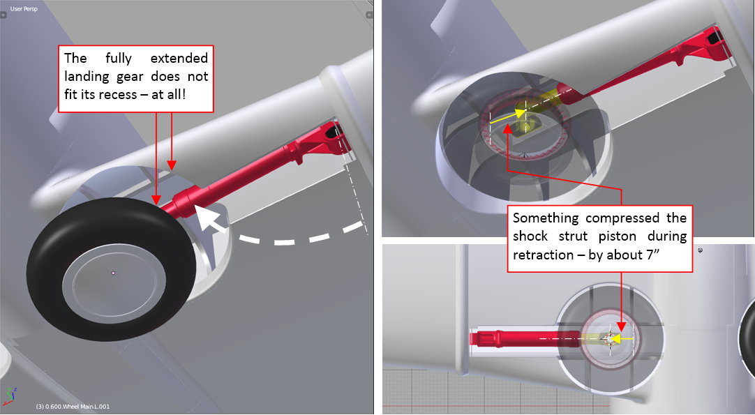
In the most of the aircraft the landing gear retracts with the shock struts fully extended. When I tried to do such a thing with the Dauntless landing gear, as in the figure above, I discovered that it definitely does not fit its recess in the wing! (see the figure below):
It seems that there was something that compressed SBD landing gear during retraction by about 7”. In the case of the Republic P-47 (which landing gear leg shortened during retraction by 9”), such a thing was widely discussed as an exceptional achievement of its designers. However, nobody even mentioned that the same issue was already resolved several years earlier by the Northrop/Douglas SBD team.
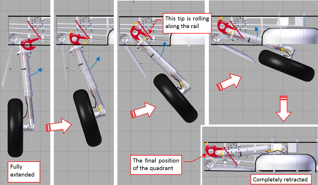
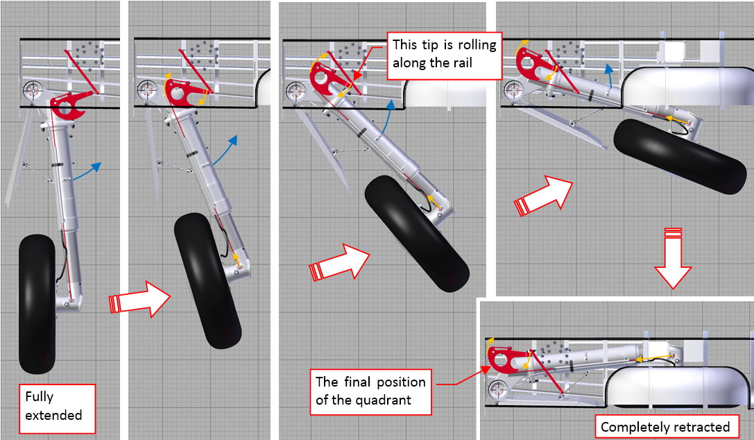
The SBD landing gear leg was made shorter during retraction by compressing its shock strut piston. This “compressing” mechanism starts with the cable that pulls the piston upward. The cable is attached to a quadrant, which rotation is controlled by the rail, fixed to the wing spar:
An additional spiral spring, attached to this quadrant (as in figure above), tightens the cable when the landing gear is extended. In this landing gear position the spring “freely” rotates the quadrant, just following the shock strut piston movements:
(You can also see how it works in this short video sequence). Note that this spring ensures that in the fully extended (free) position of the landing gear the tip of the quadrant arm nearly “touches” the rail.
This is the starting position for the piston compression. During the retraction the quadrant rotation axis is elevated upward, while its arm is dragged along the rail (there is a small roller on its tip). In the effect, the quadrant rotates, pulling the cable that compresses the shock strut piston:
You can also see how it works in this short video sequence. (Note that in this video the path of the quadrant arm tip is not perfect. This is the result of a relatively simple real-time rigging. Anyway, it gives the general idea how this mechanism works).
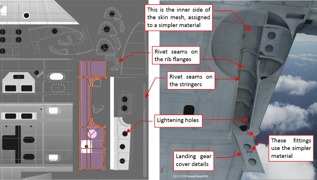
I also recreated the inner details of the landing gear recess:
During the modeling phase I already recreated two spars and two main ribs in the wheel bay. Now I refined their shape, following the available photo reference. I added also the remaining ribs as well as the stringers and the covers (at the rear part of the bay).
As you can see in the picture above, I did not model the lightening holes: as in the case of the wing flaps, I recreated them using textures:
I unwrapped meshes of all these new wing structure elements into the available space on the UV layouts that I used in the outer skin material (B.Skin.Camouflage, refined in my previous posts). The Navy painted the inner space of this wing recess in the same color as the wing bottom surfaces, so there was not any problem in assigning the B.Skin.Camouflage material to these objects. As you can see in the picture above, I also recreated the internal reinforcements of the landing gear cover. The inner side of the aircraft skin is covered with a generic material, named B.Skin.Details.Bottom. (It is assigned to the second material slot of the wing skin mesh, and set in the Material Index Offset field of its Solidify modifier). This simpler material is intended for the smaller details, and uses exclusively the generic, procedural “noise” textures for the dirt/ref effects. Thus it does not require any time-consuming UV unwrapping. In the figure above I used it also in the cover fittings. I only have to remember to alter the basic color of this simpler material when I switch to another camouflage scheme. (In the future, I will also create a similar material for the details on the upper surfaces – it will only differ in the basic color).
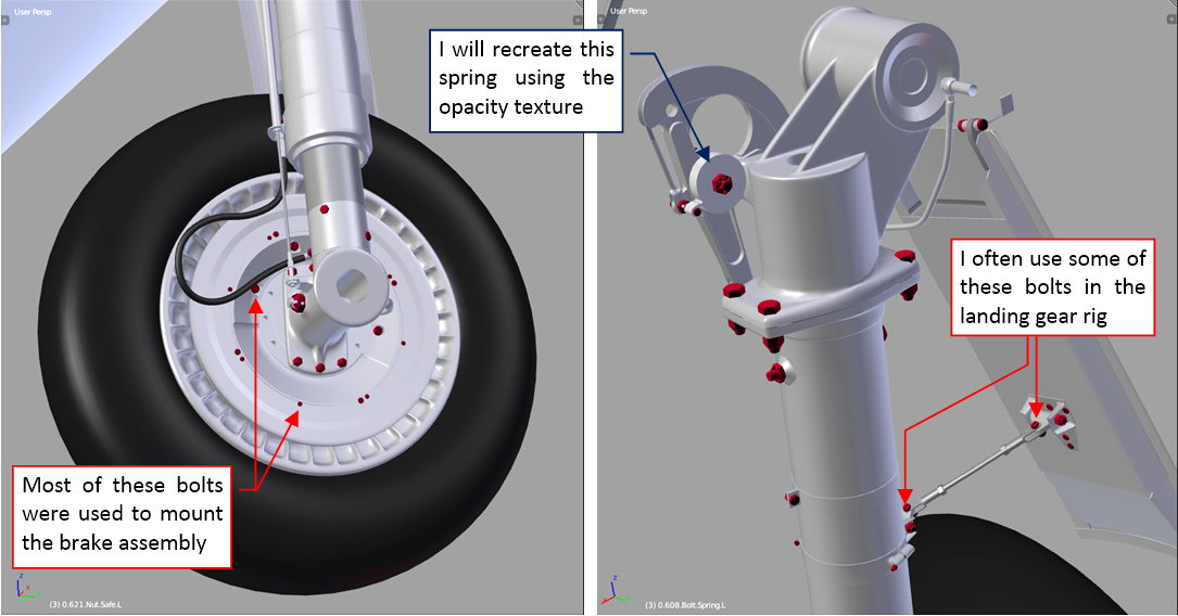
Because this B.Skin.Details.Bottom material has no regular bump map, I had to recreate more landing gear details “in the mesh”. In particular, I had to add the bolts (and nuts) visible on the reference photos. I created each of them as a separate object:
All these bolts are clones of a few basic original bolt meshes (one with the octagonal head, others with the flat one). Among these originals there are also two or three variations of the bolt length. By default these bolt meshes are covered with a generic “steel” material. When I needed to “paint” them into different color, I alter their material assignment. (In such a case, I had to switch them into the object – based material mode).
Sometimes some of these bolt objects are also useful as the reference objects in the rigging, but I will discuss it in the next post.
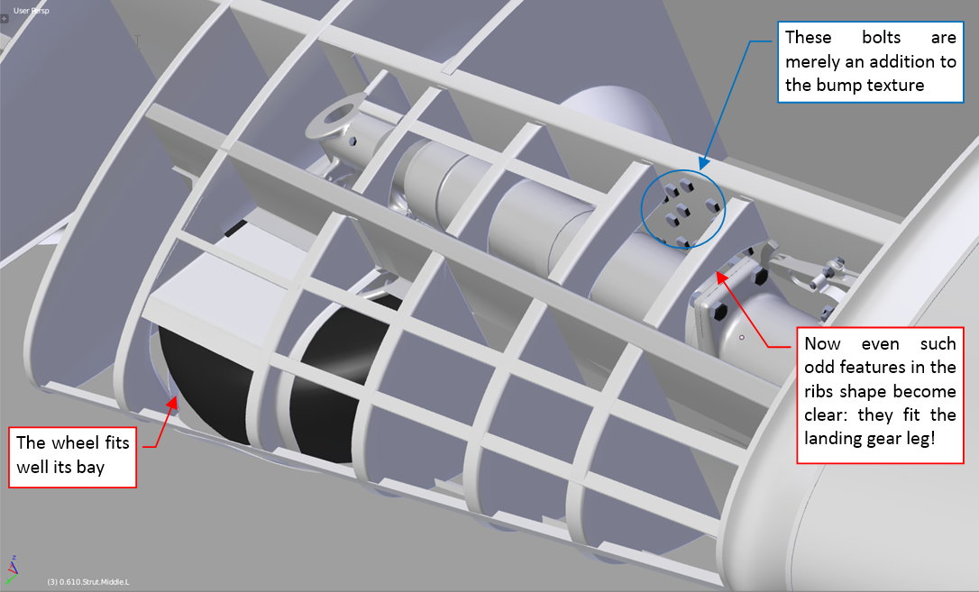
I also like to have a look at the retracted landing gear inside the wing structure. When you can see these two assemblies together, suddenly the reason for some strange features of the particular rib or spar shape becomes clear:
In figure above you can also see a couple of bolts forming an octagonal group on the rear spar. In general, I recreated most of the bolts and rivets on this spar using the bump texture. However, this was a special case: in the original airplane these bolts had quite large heads. What’s more, they were placed on a “stack” of two subsequent panels. I simply run out of the available grayscale of the bump texture in this particular place, thus I decided to recreate these “topmost” details in the mesh. (Just an exception from my general modeling tactics of using the textures as often as possible).
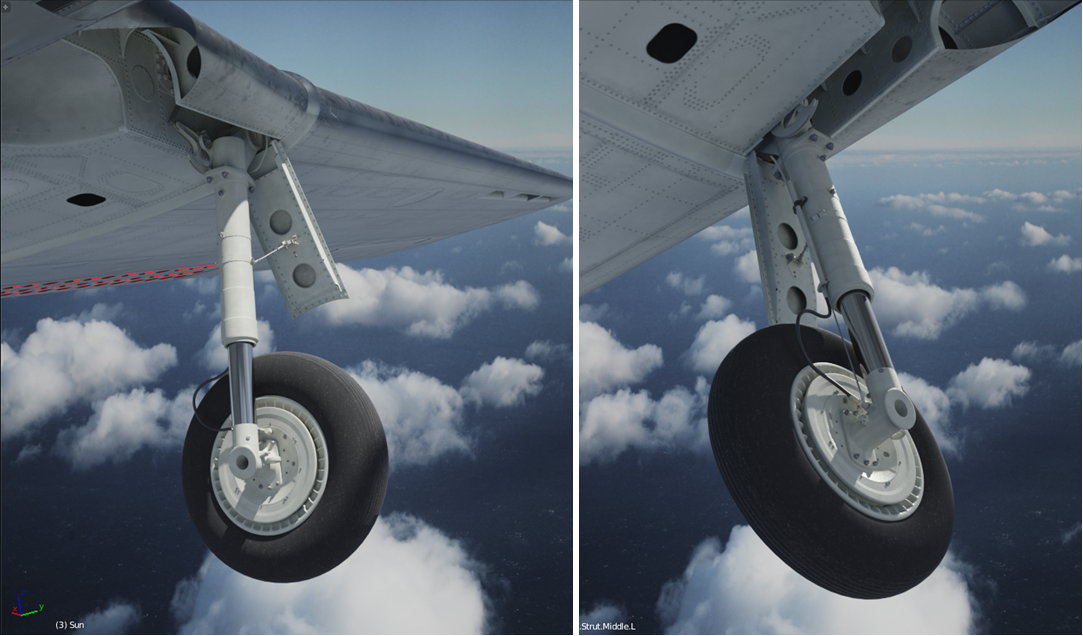
Figure below shows the complete landing gear in the open position, the shock strut fully extended:
The decision to use a simpler materials that do not require UV-mapping has certain disadvantages. The most important of them is that I am not able to paint the small stains around the landing gear bolts and other kinds of the local dirt. But this is just the consequence of the level of details that I assumed for this model.
I have to reveal that this project has a certain deadline: I promised a local modelers’ magazine to deliver detailed SBD scale plans and a couple of color profiles in January 2018. Thus currently I am focusing on the external details, because I have to recreate them to the end of this year. It includes the landing gear and a simpler version of the engine (not intended for the extreme close-ups). When it will be done, later in 2018 I will recreate the cockpit interior, as well as the detailed engine compartment and wing flaps mechanism. This more enhanced version of this model will be intended for a SBD monograph (a book). I will publish it much later.
Among the materials that I have to deliver in winter 2018 I will not enclose any close-up pictures of the landing gear or other details, thus I can use the simpler materials here. However, in such a harsh light as in Figure 80‑10 the elements covered by the B.Skin.Details.Bottom material seem too “clean”. I will definitely work on this issue, increasing the contrast of its “noise” textures to give these landing leg and brake disk a more “dirty” look.
In the next post I will describe how I rigged this landing gear. (I will describe building a kind of “virtual mechanism” that allows me to extend/retract the undercarriage using a single slider. I already used it, making the video sequences presented in this post).
In this source *.blend file you can evaluate yourself the current (i.e. non-rigged) version of this model.
Witold, as every of your updates, this one is fascinating! And congratulations for the comission on publications, they could not have hired a better modeler for it!
Wow some body did their homework! Love the attention to detail! Haven’t ever tried modeling anything from a blueprint before but it looks like a lot of work to get it right! Great work!
thorst, Bunnyhog27 - thank you!
In previous post I discussed how the SBD landing gear retracts into its wing recess:
In principle, it is simple: the landing gear leg rotates by 90⁰. However, the parts responsible for shock strut shortening during this movement increase mechanical complexity of this assembly. The figure above does not even show the deformations of the brake cable, which follows the shock strut piston movements.
For some scenes I will need the landing gear extended, while for the others – retracted. In practice, moving/rotating each part individually to “pose” my model would be a quite time-consuming task. That’s why I created a kind of “virtual mechanism”, which allows me to retract/extend the landing gear with a single mouse movement. In the previous post I already presented its results in this short video sequence. In this post I will shortly describe how I did it.
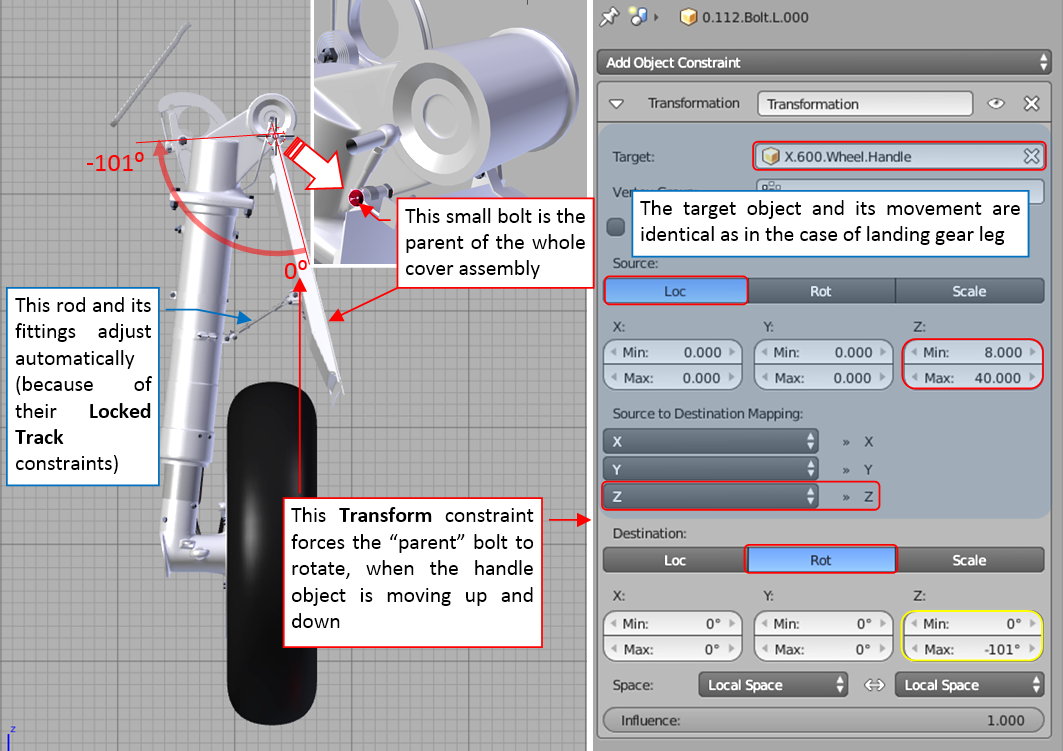
In general, I coupled some key elements (objects) of the landing gear using so-called constraints. For example, I connected the rotation of the landing gear leg with the movement of a special “handle” object. To do it, I used a Transform constraint, attached to the parent object (the axle of the retraction) of the landing gear leg:
I created an auxiliary (non-rendered) “handle” object (X.600.Wheel.Handle). The Transform constraint of the landing gear leg axle (0.604.Strut.Axis.L object) converts the handle linear movement into landing gear rotation. Thus when I shift the handle object upward, landing gear leg rotates, retracting into its place in the wing. To restrict the range of this rotation, I assigned to the handle object additional Limit Location constraint. It restrict its possible movement to a 40-unit long span along local Z axis.
The more detailed explanation of my methods for the “mechanization” of the landing gear would take too much space in this post. However, some years ago I published an article on this subject (in “Blender Art Magazine”):
To read this article, click the picture above or this link. I hope that this publication will explain you the general idea and typical implementation of such a “virtual mechanisms”.
to be continued in the next post.[SUB](The original text was longer than 10K characters)[/SUB]
continuation of the previous post
The format of this post allows just for a quick review of the SBD landing gear constraints (one picture per a subassembly). Thus the next element coupled with the handle object (using another Transform constraint) is the landing leg cover:
In the previous post I added many bolt objects to the landing gear, and mentioned that some of them will have an additional use. So this is just such a case: I set the forward bolt of the cover hinge as the parent of the whole cover assembly. (Because it lies on its rotation axis). A Transform constraint, assigned to this bolt, forces it to rotate in response to the handle vertical movements. Note that the range of rotation of this cover (101⁰) is greater than the range of the landing gear leg rotation (90⁰).
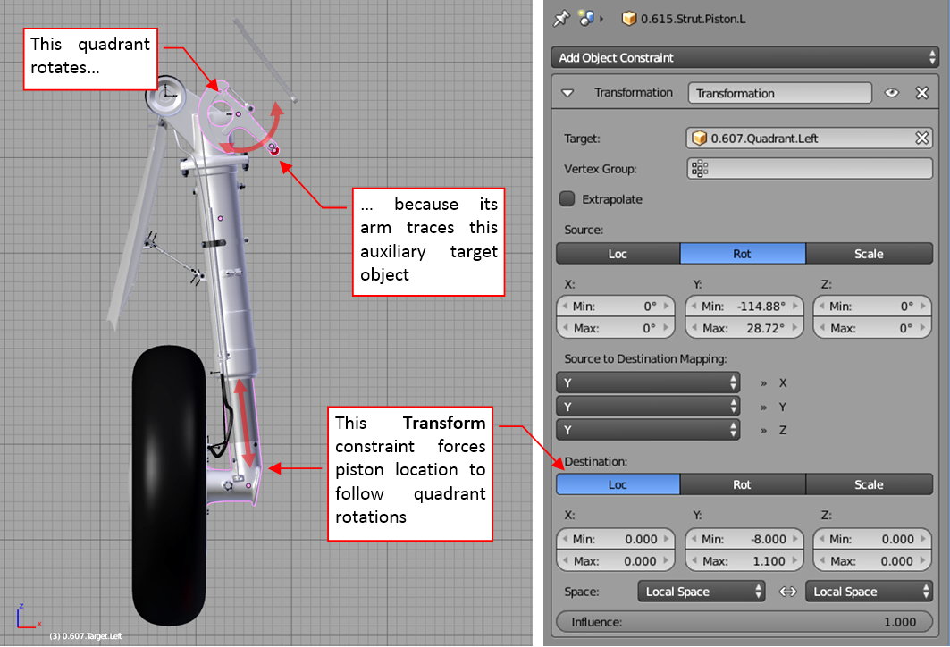
Another Transform constraint converts the rotation of the quadrant object into movements of the shock strut piston:
This relationship seems quite straightforward: when the quadrant rotates upward, the piston shifts up, when it rotates downward, the piston shifts down – as if they really were connected by the cable. Rotation of the quadrant is forced by its Locked Track constraint, which arm “tracks” the auxiliary (non-rendered) target object (the red, small circle in the figure above). Effectively, location of this quadrant target controls the shock strut position.
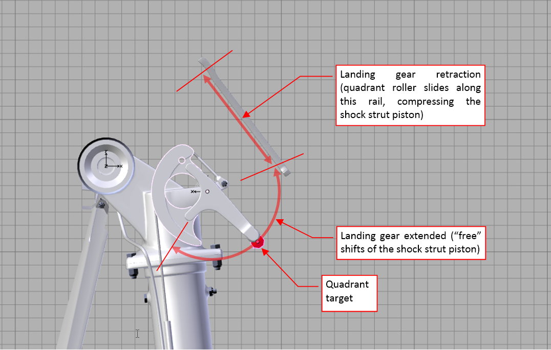
The full motion path of the quadrant target object contains an arc and a straight segment:
The arc corresponds to possible piston positions for the extended landing gear (see this short video sequence). The linear segment corresponds to the forced compression of the shock strut during retraction, when the quadrant arm tip slides along the internal rail. (You can see this motion here, although in this video the path of the quadrant arm tip is not ideal).
I did not want to use the animation motion path here, because it creates a “deterministic” movement (“frame by frame”). Instead, I wanted a general solution, controlled by a handle object instead of the animation frames. Thus this is the most complex subassembly in this landing gear rig. I will describe it in two pictures: one for the extended landing gear (implementation of the movement along the arc), the other for the landing gear retraction (movement along the linear segment).
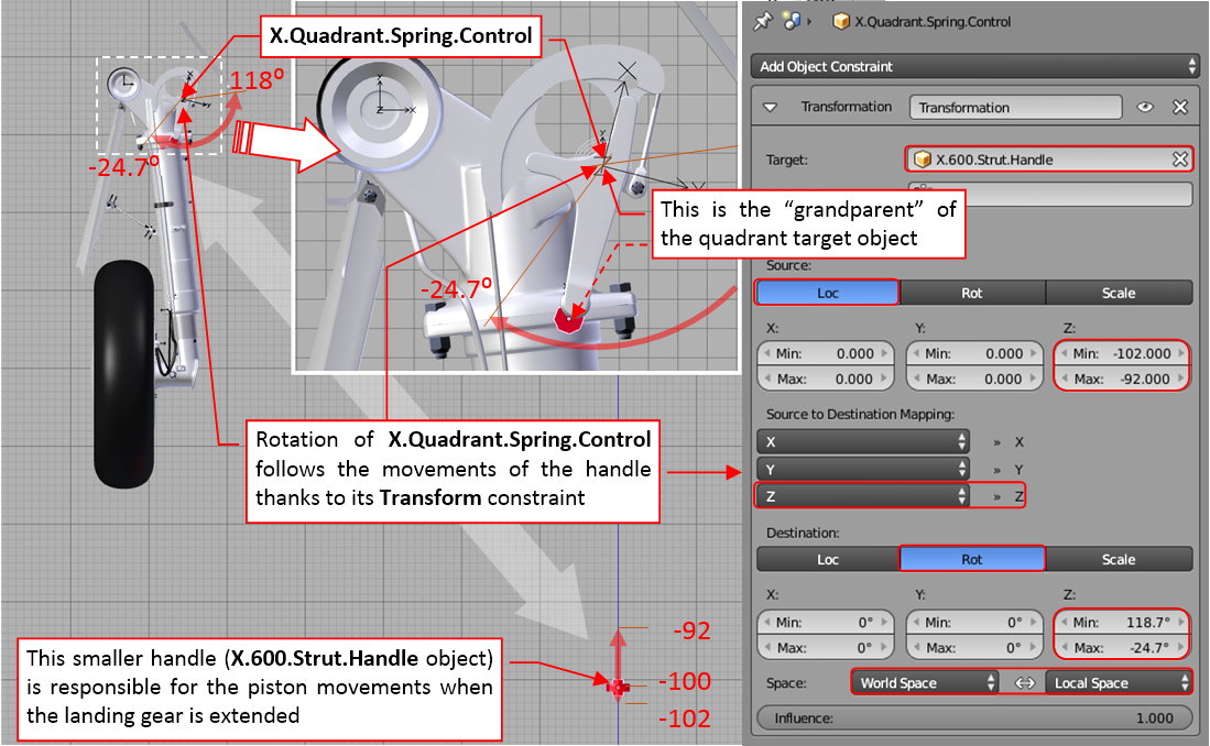
When the landing gear is extended, the rotation of the quadrant target is forced by its “grandparent” object. This is an Empty instance, named after the source of the original movement it mimics: X.Quadrant.Spring.Control:
A Transform constraint converts the vertical movement of the additional handle object (X.600.Strut.Handle) into rotation between -24.7⁰ and +118⁰. There is another Empty object (0.607.Target.Left.Parent), attached (by the parent relation) to the X.Quadrant.Spring.Control. Simultaneously, 0.607.Target.Left.Parent is the parent of the quadrant target object. (The reason for such an indirect relationship will become clear in the next figure). When the landing gear is extended, this chain of “parent” relations forces the quadrant target object to move along the arc path when the handle object moves up and down. To not exceed the minimum and maximum angles of this movement (and in the effect – the lowest and highest shock strut piston position), the location of the handle object is restricted by a Limit Location constraint.
Note that this smaller handle is the child of the main handle, used for the landing gear retraction (X.600.Wheel.Handle). Note also that the Transform constraint that forces this rotation, evaluates the handle position in the World Space (figure above, bottom right). This means that regardless of the position of the smaller handle, the shock strut will be fully extended after moving the main handle along the first few units along its way up. (So that I do not have to care about the initial piston position when I am starting landing gear retraction: it will set up itself).
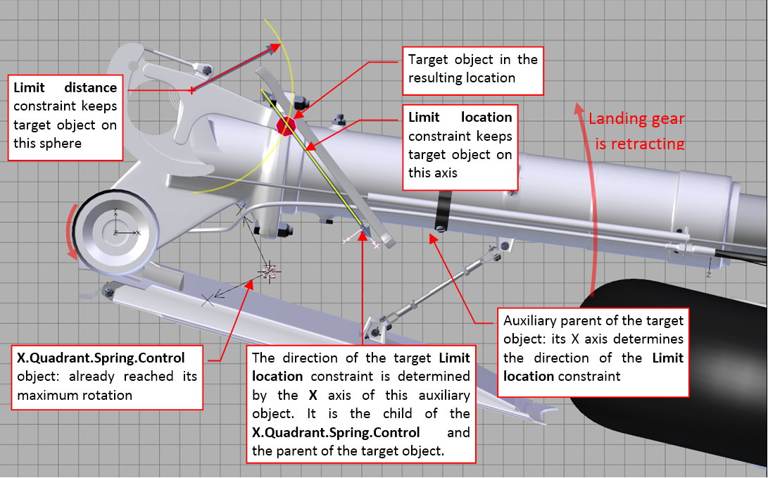
During landing gear retraction the locations of the quadrant target, its parent, and “grandparent” become dispersed. Figure below shows how it looks like in the middle of the main handle (X.600.Wheel.Handle) movement:
The parent (0.607.Target.Left.Parent) of the quadrant target object just “delivers” it to the rail line and stops there. (This is the end point of the rotation of its parent: X.Quadrant.Spring.Control object, as you can see in the previous figure). Then the quadrant target object is “dragged” by the landing gear retraction along the rail. I tried to obtain this effect by assigning it two constraints:
In theory, for such a constraint combination there is always just a single possible location of the target object (marked in the figure above). Unfortunately, it seems that Blender treats these constraint with certain “flexibility”. In the effect, the quadrant arm tip “sinks” into the rail. This effect is especially visible at the beginning of the landing gear retraction. Well, I tried hard but I could not find a better solution for this movement. Finally I concluded that I can left it in this state: this is a small part, which movements are partially obscured by the wing recess. When I need to make a close up, I can prepare a “deterministic” animation motion path for the quadrant target object.
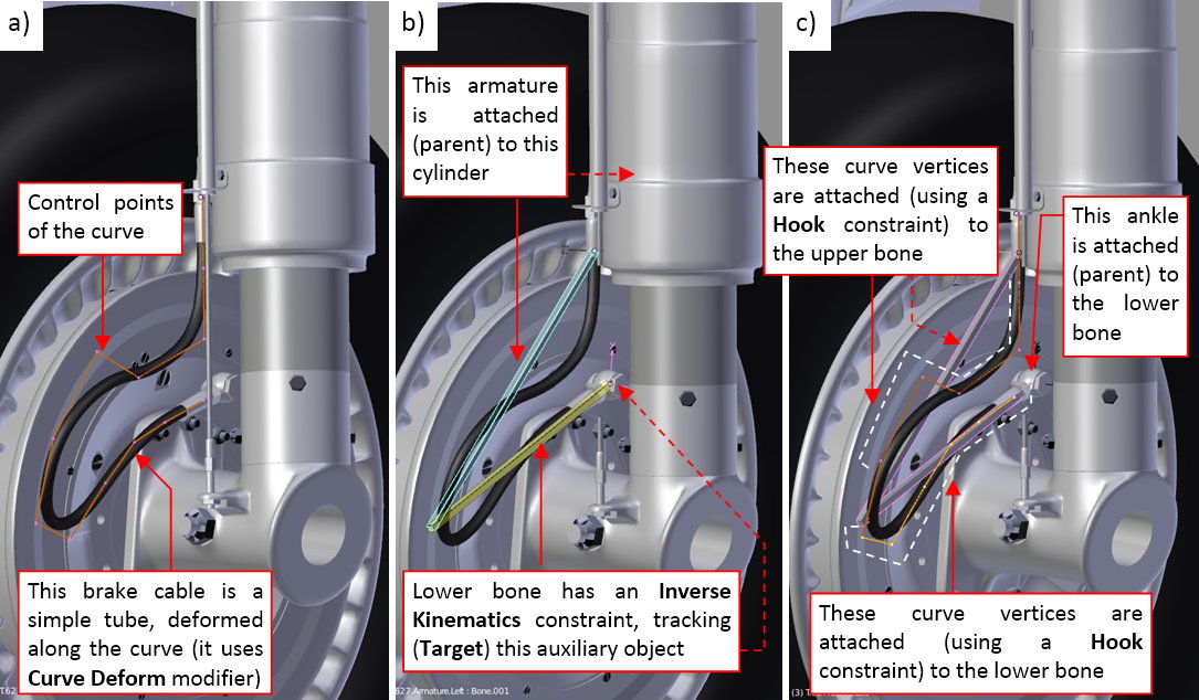
The last rigged subassembly of this landing gear was the elastic brake cable. Because I used in this implementation another (better) solution than described in my article and book, I will discuss it shortly below
First, as in my previous model, I formed the curve (figure “a”, above), that deforms the simple tubular mesh into the brake cable. (I used a Curve Deform modifier here). Then I created a simple armature consisting two bones: upper and lower (figure “b”, above). The armature object is attached (by a parent relation) to the strut cylinder. Thus the origin of the upper bone is also fixed in this way. I assigned to the lower bone an Inverse Kinematics constraint, and set its Target to an auxiliary Empty object at its end. This target object is indirectly (via the brake disk) attached to the piston. In the effect, this armature follows every piston movement in a natural way – like a pair of the torque scissors. Finally I attached subsequent curve vertices (control points) to the nearest armature bone (figure “c”, above). I also attached (via parent relation) the ankle object (at the bottom end of the brake) to the bottom bone. (So that it will follow its rotation). In the effect, the brake cable deforms when the shock strut piston is shifting, following its movement in a natural way. See this short video how it works.
In my previous model (the P-40B) I used for the same purpose a different, less effective combination of the constraints. I think that in the future I will always use the solution as in figure above, not only for the brake cables, but also for the torque scissors (the SBD landing gear did not have such an element).
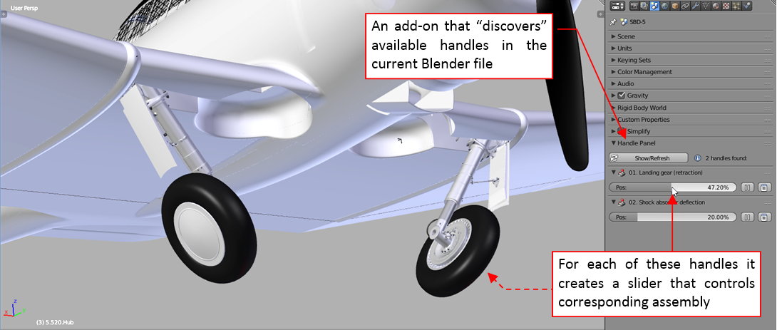
Finally, I applied my Handle Panel add-on to create a convenient landing gear controls among the Blender panels:
See this short video how it works. Now I can extend/retract the landing gear with a single mouse movement. I even do not have to know, where their handle objects are – the add-on will discover them automatically. (I just have to arrange them in the model space in a certain way – see the add-on description for details. This is a general utility, you can use it in your own Blender models).
The next part to recreate is the tail wheel assembly. I will report this step within two or three weeks.
In this source *.blend file you can evaluate yourself the current version of this model.


