SBD Dauntless (US Navy dive bomber)

Thank you, smith123! Precisely - when I am making such an aircraft model like this, I always analyze its details, learning what the designer wanted to achieve. (Looking for solutions of the typical engineering cases, technology used for their solution, and the other elements).

In this post I will finish the “general modeling” phase of the wing, recreating the last missing elements. Of course, the result presented in this section is not the “final product”. It is just detailed enough for the next phase — applying textures and materials. (I will do it when I form the whole model). After applying the textures I will come back to this wing during the detailing phase, and recreate all its small details (like various small openings, aileron hinges, running lights, landing light, etc.).

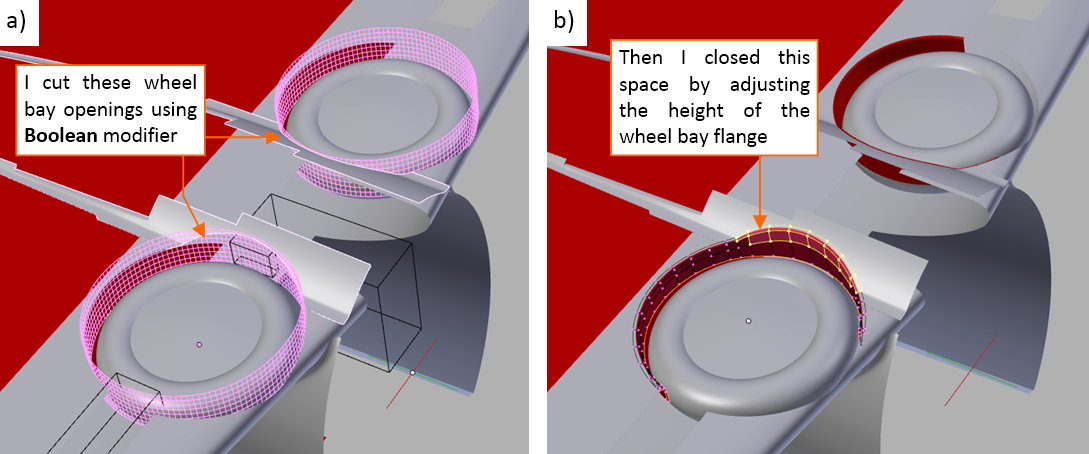
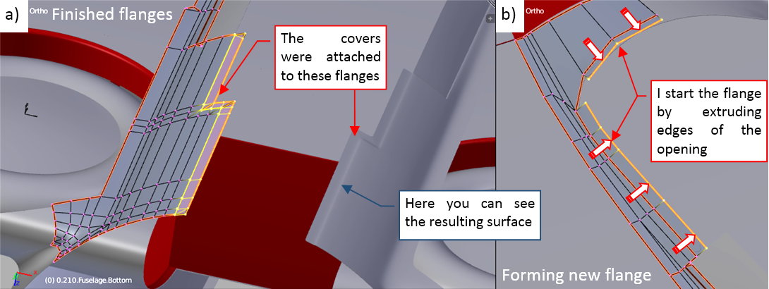
Finishing the wheel bay, I decided to add the rounded flange around its edges:

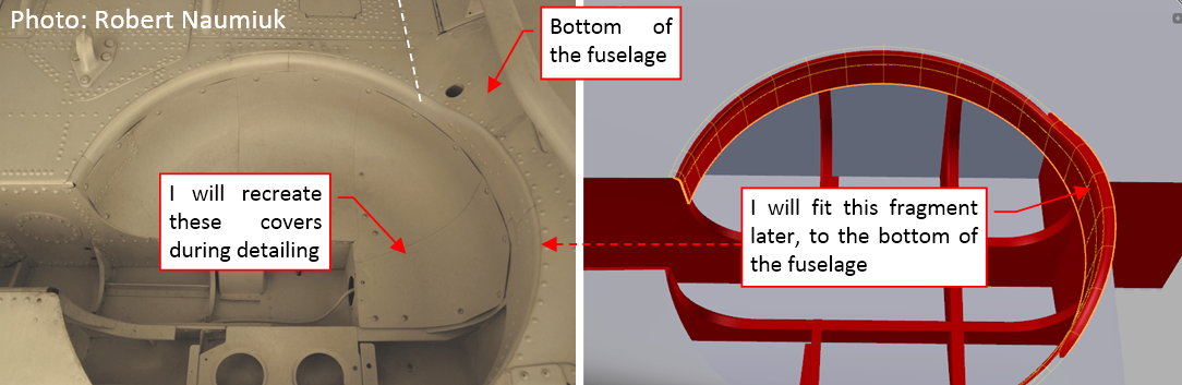
I just did it because I do not like to see a non-realistic, “suspended in the air” edge of an opening. A part of this flange has to fit into the bottom of the fuselage. At this moment I left on that flange an “informal”, elevated fragment. I will fit it to the fuselage when it will be ready.

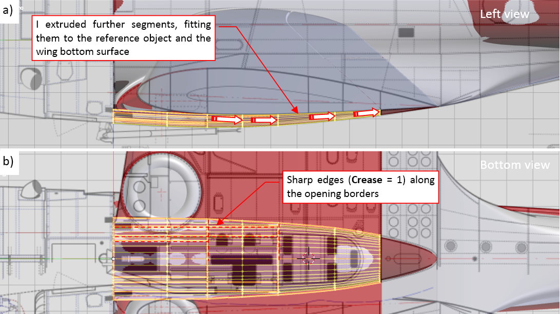
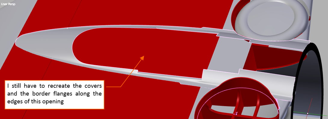
There is another detail which is too subtle to be found on any scale plans. It is the shape of the landing gear leg bay, speaking more precisely —of its front edge:

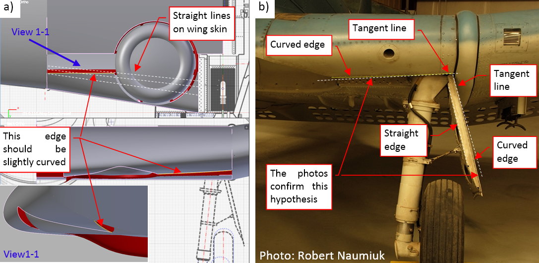
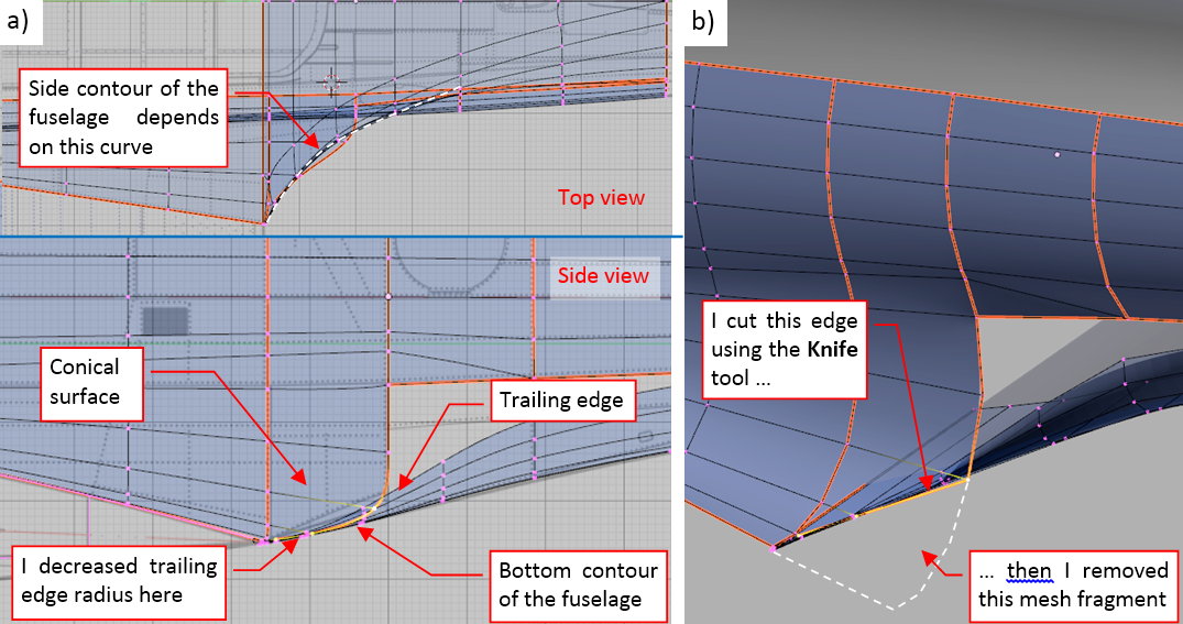
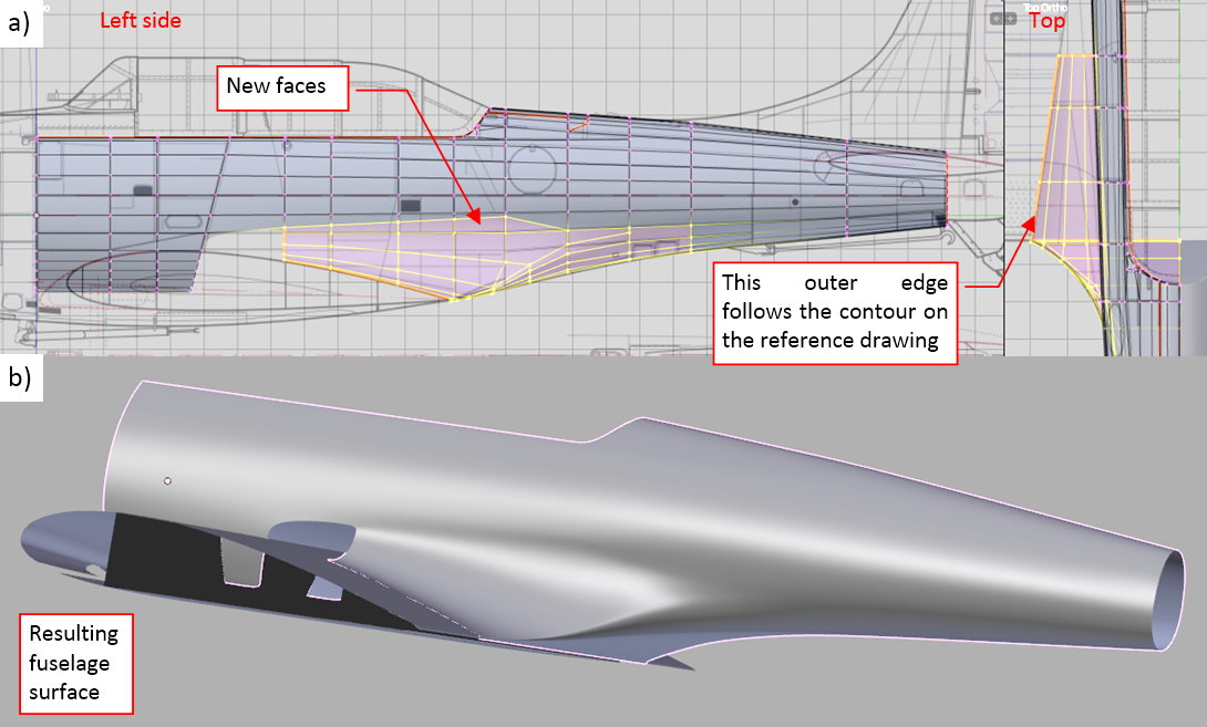
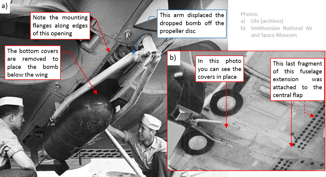
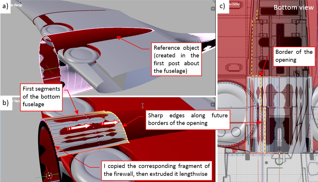
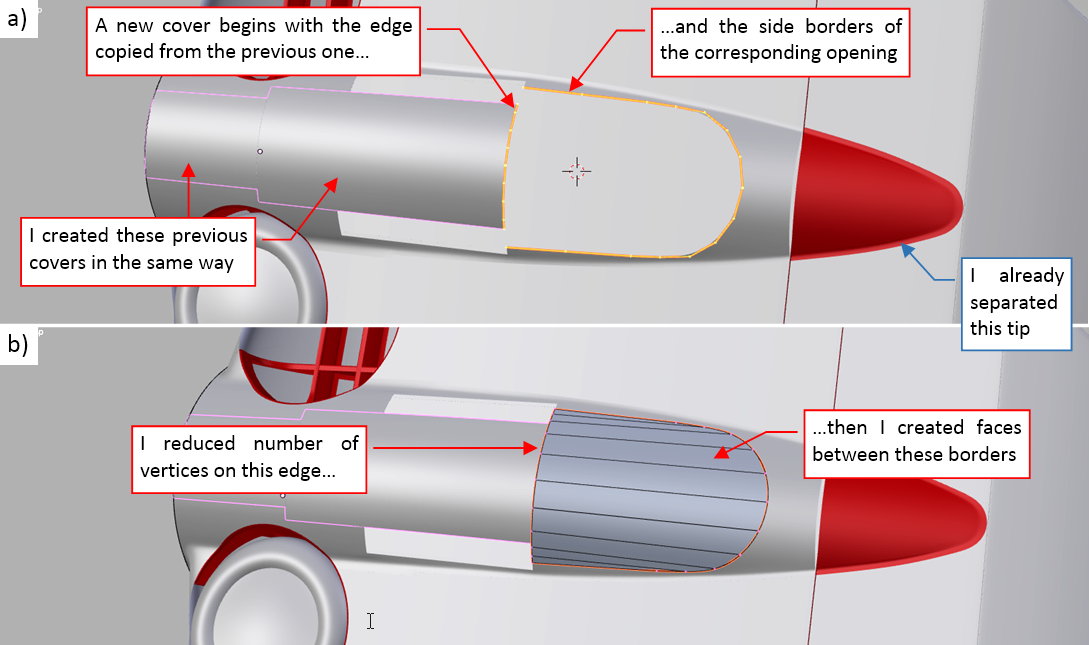
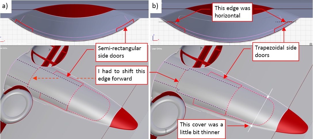
In the top view the front edge of this opening is a straight line, perpendicular to the aircraft centerline. Such an edge goes across several theoretical straight lines that you could draw on the bottom wing surface (see picture “a”, above). This means that in the front view this edge forms a gentle curve.

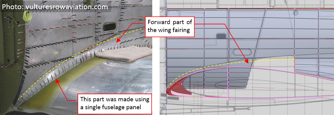
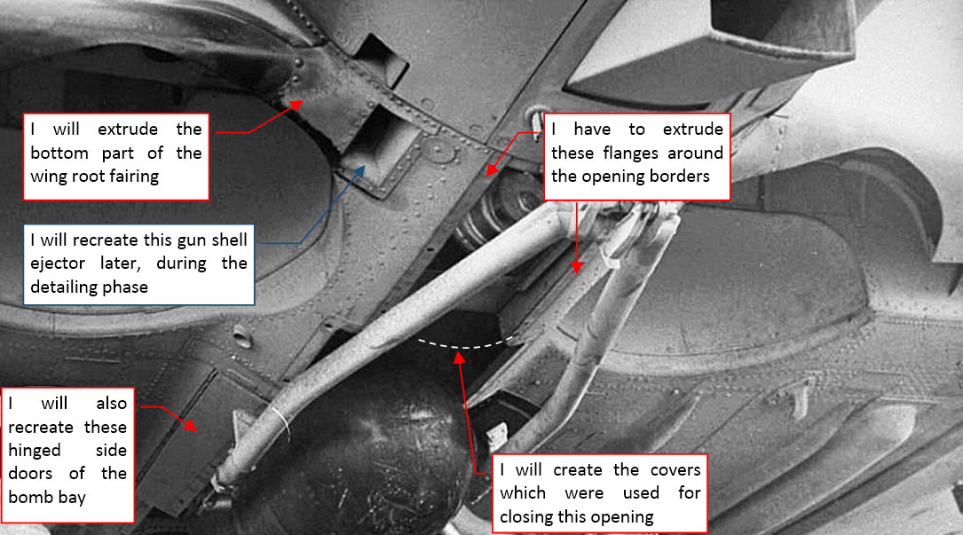
Initially I did not know if the Dauntless designers reproduced such a geometrically correct, but technologically more difficult shape. (Such a curved shape is more expensive because it requires additional formers for the wing skin panels and landing gear cover). I could imagine the situation when they decide to simplify this edge to a straight line. Fortunately, I have many high-resolution pictures of various restored SBDs. Photos of the landing gear confirm that this edge was curved (see picture “b”, above).

Another element I added was the solid rib that closes the center wing section. It is a standard Northrop solution for joining multicellular stressed-skin wing, designed in 1930 for their Alpha aircraft. Both wings were joined by multiple bolts evenly distributed around the airfoil circumference. The forces from the bolts were transferred to the wing skin via “L”-shaped flanges. You need to place a stiff rib between such flanges, because otherwise the whole structure would collapse. That’s why the rib closing the wing section is a solid, thick aluminum plate:

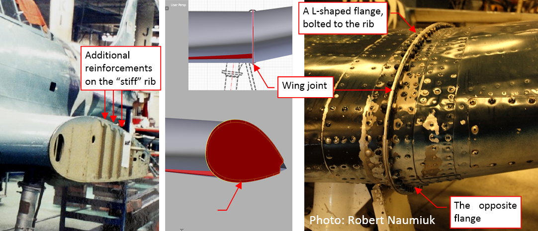
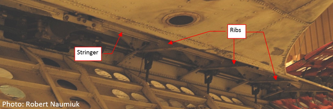
I am not sure if I estimated properly the thickness of this rib. Anyway, I did it using a Solidify modifier, so it will be easy to alter this setting later. Because of this unusual thickness I am not sure if I will recreate the openings in this element (you can see them on the photo) using textures. The alternative method is to modify this mesh (it should be not very complicated, because it is a flat plate). During the detailing phase I will also recreate the vertical reinforcements visible on the photo.

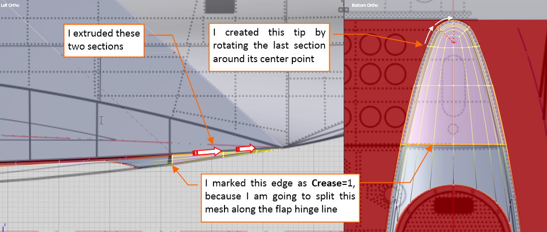
I started the bottom flap of the center wing section by preparing the auxiliary spar running along the flap hinges:

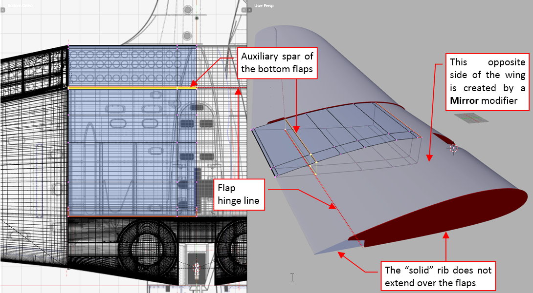
As you can see, I also created the symmetric, right side of this wing section, using a Mirror modifier.

The flap is created in the same way as the flaps of the outer wing panel. I separated the bottom part of the wing trailing edge into the flap skin. I added a very long, thin cylinder as the flap hinges. I copied the trailing wedge from the outer wing panel and placed it on the trailing edge:

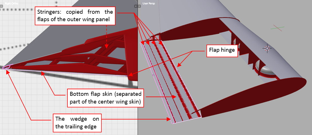
Then I copied the flap stringers from the outer flaps. In fact, I used just the cross sections of these original objects, extruding them into new stringers. I used Mirror modifiers to create the opposite sides of all of these spanwise flap reinforcements.

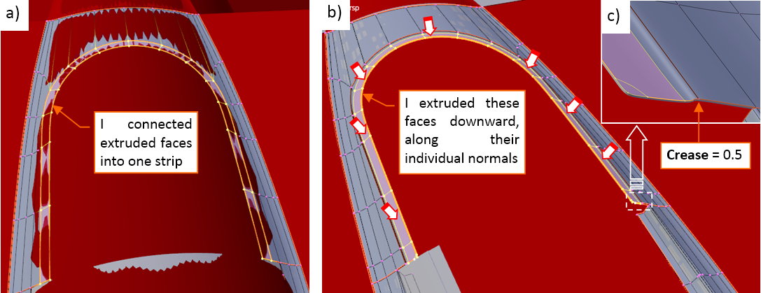
In the next step I copied from the outer flaps the “standard” flap ribs (they all are clones that share the same mesh - see picture “a”, below):

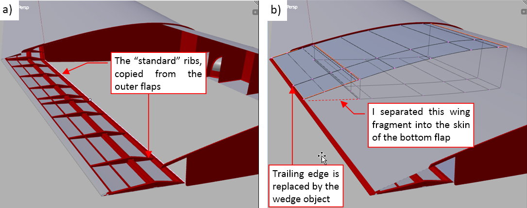
Finally I modified the upper part of the center wing mesh, integrating it with the trailing wedge (see picture “b”, above).

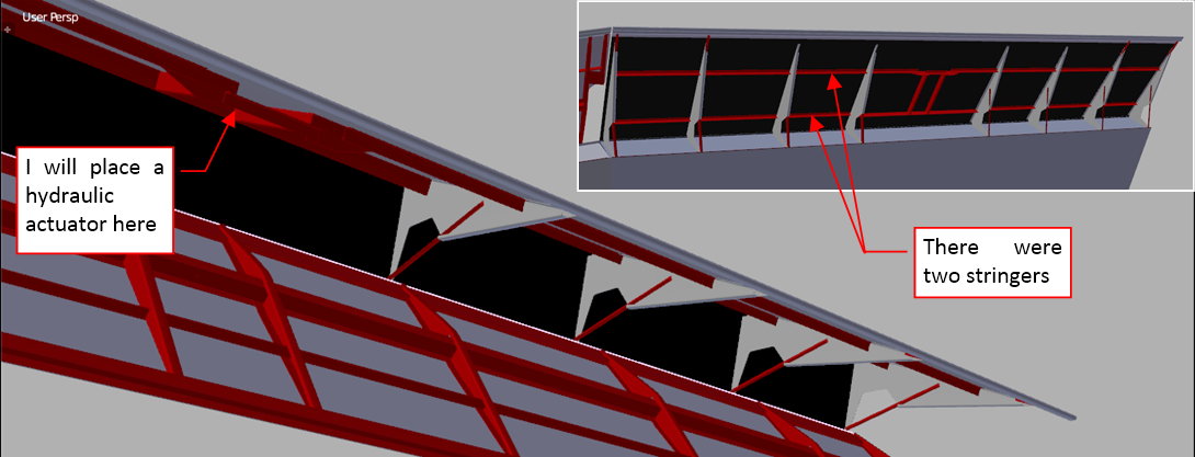
When you open the split flap, you can see the internal structure of the wing:

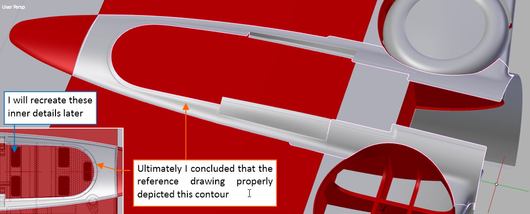
I studied the available photos of the flap bay in the center wing, then recreated the key ribs and spars:

Finally I organized the whole wing into the appropriate hierarchy. At this moment the root element is the wing center — more precisely, its rear part:

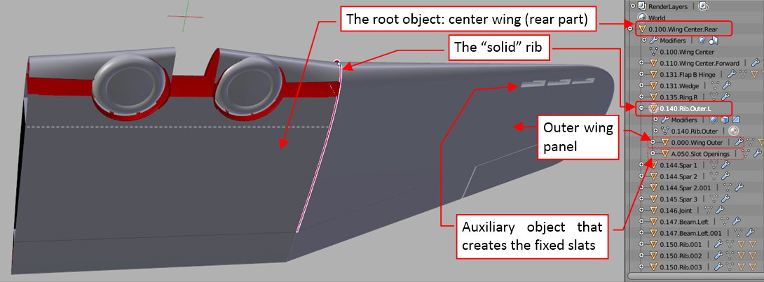
I placed all external wing elements on layer 1, while all internal parts are on layer 11. The auxiliary “cutting tools” used in the Boolean modifiers are in layer 9. To avoid “circular reference” conflicts I assigned the outer wing panel and the object that cuts its fixed slats to the common parent — the ”stiff” root rib.

In this source *.blend file you can check all details of the wing presented in this post.

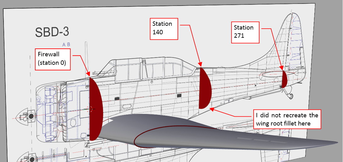
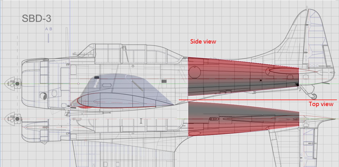
In the next post I will start working on a more difficult part — the fuselage.

Before I start forming the mesh of the SBD fuselage, I will prepare an auxiliary object: the simplified version that will help me to grasp the general concept of its shape. I will describe it in this post.

In the first step, I created the three key bulkheads:

First one — the firewall — seems to have an elliptical shape:

The contour of the station 140 on my plans is copied from one of the photos which I have found on the Vultures Row Aviation web site:

For this conceptual shape I replaced the bottom part (after the trailing edge) with the curve extrapolated from the further tail cross sections.

Finally, in station 271, which closes the main fuselage structure, I had to extrapolate its upper part:

Then I extended between stations 140 and 271 a mesh, forming in this way the simplified tail (without the wing root fairing):

I put another edgeloop in the middle of this tail to fit its contour in the side and top views.

In the next step I recreated the mid-fuselage:

In this concept object I entirely skipped the wing root fairing — because it requires a lot of work. I will recreate it directly in the final fuselage object. Note that the fuselage contours along the cockpit are straight lines. This detail is visible on many photos.

I added in the middle of the cockpit another “bulkhead” edgeloop, and used it to determine shape of the bottom part of this fuselage:

I fitted the contours of the fuselage that protrudes from the wing bottom surface into the contours in my reference drawings. It took some iterations to fit them. (The contour you can see in the bottom view was copied from original Douglas photo, so it is an important reference. The side view is not based on such a confirmed information). To preserve the straight edges on the cockpit sides, I had to move this central bulkhead along the fuselage centerline using the Edge Slide command. I was able to move or scale this edge only along the Z direction.

Finally, when I finished this element, I checked if the cockpit sides are still straight, like before. They were not:

As you can see in the picture above, I used an auxiliary horizontal plane set in the contrast color to see the effective shape of the fuselage mesh. I placed it just above the “longeron” edge that runs along the maximum width. The fuselage contour you can see on this plane is bent in the front of station 140. I think that such a shape is the effect of the “saddle”-like shape of the fuselage in this area. I am glad that I identified this issue on this simplified model. I will try to avoid such an effect in the final fuselage by directing all the lengthwise (“longeron”) edges along their real-life counterparts (upper-left to bottom-right on the side view).

In this source *.blend file you can check all details of the model presented in this post.

In the next post I will continue working on the fuselage. (I will use the object crated in this post as the reference).

In the previous post I created a simplified model of the SBD fuselage that helped me to identify the eventual troubles in the modeling process. In this post I will create the mid-fuselage (more precisely: its upper part).

I always try to think ahead about the mesh topology required for a given shape. In the case of the subdivision surfaces that are used here, this approach is extremely useful. When you place vertices of the initial bulkhead in the proper places, it greatly simplifies further modeling. To mark some “longeron” edges as “sharp” (Crease = 1), I started with a thin mesh “strip” instead of a single contour:

As you can see in the picture above, it is built around the cockpit sides. Looking on the photos you can notice that one pair of the main longerons forms the side edges of the cockpit. It will be the upper edge of my fuselage. (The part below the windscreen seems to be a separate assembly, riveted over the longerons (see picture “a” below). I will create it later:

I recreated the small fillet around the cockpit edge using two parallel edges placed close to each other (see figure “b” above). I could obtain similar effect using a single, partially sharp edge. However, in such a case the contour of this fillet on the fuselage cross section would have a shape that significantly differs from the circular profile in the real aircraft. What’s more, I will split these double edges at the rear edge of the cockpit opening. I expect that in this way they will help me to shape its rear, rounded corner.

I extended the initial mesh strip from the firewall to station 140 (station locations — see previous post). After fitting vertices of this “bulkhead” edgeloop around station 140, I inserted in the middle of this mesh a new edge, just at the end of the skewed station 54. Then I removed the bottom fragment from the rear part of the resulting mesh:

To avoid the curved contours of this mesh in the top view, I directed the lengthwise edges little downward in the second segment of this fuselage (see picture “a” below):

To verify if the cockpit sides are really straight in the top view, I placed (on the tools layer – 10) many straight “stringer” probes (see picture “b” above). All of them are horizontal, arranged like the real longerons in the airplane (see picture “a” below):

For the properly shaped surface, these probe objects should minimally protrude from the fuselage skin (as in picture “b” above). I used them to apply small adjustments to this mesh.

When the cockpit sides are ready, I recreated the upper part of the station 140, and extruded it toward the cockpit. In this way I obtained the initial strip of the tail upper surface (see picture “a” below):

It is relatively easy to prepare in this mesh a rectangular opening for the gun doors. The general rule of the subdivision surfaces is that their sharp edges (i.e. edges which Crease = 1) have the same shape as the free edges (for example — opening borders). Thus, if I incorporate into a smooth surface an area encompassed by sharp edges, I can later remove its inner faces without altering the shape of the outer mesh faces.

But how to obtain a smooth surface around a sharp edge? It is simple: place it in the middle of a flat face of the control mesh. I did so. As you can see in picture “b” above, it is enough to make the three vertices on every bulkhead collinear. (In practice, small deviations from the theoretical line still produce acceptable results).

You can learn more about this and other useful properties of the subdivision surfaces in Vol. II of the “Virtual Airplane” guide.

In the next step I cut in this mesh strip the skewed rear edge of the cockpit opening:

After removing the unnecessary vertices, I created a few new faces that finally joined this fragment with the rest of the fuselage mesh. As you can see in picture below, I also inserted another edgeloop just after the cockpit rear edge:

This additional edgeloop and the few vertices in the corner control the surface curvature around of the cockpit opening. As you can see in the picture above, one of the resulting mesh faces has five vertices (so-called n-gon). In general, it is possible to decompose it into a triangle and a quad. However, I carefully examined the resulting surface and decided that this additional vertex does not deform in any way its smooth shape. Thus I decided to leave it “as it is”.

Note that there is a single vertex in this mesh that controls the shape of the fuselage skin in the corner of the cockpit opening:

I modeled it to resemble the original shape as I can see it on the photos. However, I will return to this fragment during the detailing phase of the modeling. With the cockpit canopy in place, I will then re-examine my photos and decide about the further details (for example — cutting the smaller openings for the ammunition feeders on the gun doors sides, which were introduced in the SBD-3).

In this source *.blend file you can check all details of the model presented in this post.

In the next post I will continue working on the fuselage.

Superb work Witold - you never cease to amaze us. Keep up the good work!

Cheers, Clock.

no questions this is nice work

but where do you get so much references pictures !

I mean one thing I learned is that the web most of the time don’t have so many details!

keep it up

happy bl

Clock, thanks a lot! I am a “long-distance” type, tere is no worry about steady feeding this thread with new posts (I do it every Saturday :)).

Thank you, Ricky! Answering your question: I collected about 1200-1300 photos of this airplane. Half of them made my friend during his trip to the USA air museums. (His name is Robert Naumiuk, and most often I use his photos in my posts). The other half I collected from the Internet. Surprisingly, on the Internet you can find the most interested ones: wrecks and photos from various restorations. Just try to search the images.google.com for “Dauntless restoration”, and you will get it!

Hi Witold!
You are doing really amazing work. To take the opportunity I would like to thank you for your amazing ebook!

McGavish - thank you!
However, looking on your highly realistic armor models, I think that the model described in this book is still relatively simple!

Such an inspirational thread! not much to say here other than utter amazement and awe to the level of detail and research done.

Tommy1441 - thank you!
You know, because of the years I spent writing the book, the old habit forces me to report the progress of this work in similar style :slight_smile:

In this post I will begin the wing root fairing and recreate the tail of this SBD fuselage.

To be able to fit the fuselage to the wing, I started by creating a new set of the “bulkhead” edges. I placed them at the stations of the original bulkheads:

In most airplanes the wing root fairing and tailplane fairing are created from additional sheet metal elements, fastened to the fuselage with multiple bolts. In the case of the SBD lineage — Northrop Alpha, Gamma and BT-1 — the wing root fairing was the integral part of the fuselage structure. (However, the SBD tailplane fairing had the conventional, “fastened” design).

At the beginning I decided to form the rear part of the wing fairing as a separate object. In this way I will avoid the messing with the topology of the existing mesh. I will merge these two meshes later. Thus I copied into this new object a part of the fuselage mesh, and combined it with the initial part of the fairing cone:

It is always worth to analyze how the modeled element was built in the real aircraft. Let’s look on the photos:

On the picture above I marked straight lines in white, circular cross-sections in red and other curves in yellow. Note that the stringers connecting the circular sections are straight or gently curved. If you would think how this part was built in a workshop, it makes sense. It is not too difficult to recreate the circular cross sections of the fairing in the subsequent bulkheads. Then you have to set these bulkheads at the corresponding stations and connect them with the thin stringers. In this process you can always bent (a little) the initially straight stringer. That’s why all the lengthwise lines on the photo are straight or form a gentle curve.

To ensure that I will recreate this shape properly, I placed three auxiliary stringers as they were located in the real airframe:

Ideally, the outer edges of these test stringers should protrude a little from the wing root fairing surface. Using such them as indicators, I added new edgeloops in the middle of this mesh, and adjusted its bottom shape, fitting it to the wing:

For the further work on the wing root fairing I need the tail. I extruded it from the station 140 up to station 271. Then I put one of the middle bulkheads at station 195 as a reference. Finally I adjusted the shape of this surface to the contours drawn in the side and top views. I did it using three new “bulkhead” edge loops, inserted in the middle of the tail:

Evaluating the shape of this newly created part I examined not only the resulting surface, but also the control mesh. In the case of a fuselage, some geometrical problems are more evident when you check the flow of the lengthwise (“longeron”) edges. In this case I noticed that something is wrong with the last segment of the tail.

The edge marked in yellow in the picture above corresponds to a real longeron on the fuselage. On the photos this longeron seems to be nearly straight. However, in the last segment of my tail its direction is altered:

I re-examined my photos and concluded that I made mistake in the shape of the bulkhead at the end of the tail (station 271). The top contour of this bulkhead had larger radius than in my model. (However, I have an excuse: this part of the last bulkhead is an extrapolated shape, because its upper part is inside the tailplane — see the bulkhead pictures in the post where I started working on the fuselage. On these pictures you can see that I proportionally decreased width of the whole bulkhead contour. This deformation was the direct reason of this mistake). I corrected the tail shape, increasing the corresponding radii in the two rear bulkheads:

Finally I modified edges around the gun door opening:

I prepared horizontal edges of this opening earlier, while shaping the upper part of the station 140 bulkhead (see my previous post). Now I added another sharp edge that closes this opening. Note that for such a rectangular border I avoid crossing two sharp edges — because the resulting corner would create additional elevation above the smooth fuselage surface.

In this source *.blend file you can check all details of the model presented in this post.

In this file you can delete the vertices inside the gun door opening (as in figure above), and check that the shape of the fuselage around the gun bay remains unaltered. I “programmed” such a result into this mesh from the beginning. (I did it by appropriate adjustment of the few vertices in the first tail bulkhead).

In the next post I will form the difficult, rear part of the wing root fairing.

In this post I will finish the rear part (the most difficult in this aircraft!) of the wing root fairing. I started this fairing in the previous post.

I previously formed the basic cone, up to the trailing edge. I created it as a separated object, to easier modify its topology. Now I copied into this mesh the further fragment of the fuselage, above the fairing (see figure “a” below):

I also created a small rounded edge along the trailing edge of the wing (figure “b” above) (more precisely — along its closing wedge, as in figure “c”).

This inconspicuous part plays the key role in forming of wing root fairing. First, I extruded it up to the station 140, then I inserted in the middle additional edgeloop. Then I could bent this fragment at will, by moving and sliding this middle edgeloop. I aligned this mesh patch to the wing fairing contour in the top view. Then modified its vertical shape, bending this mesh patch around the fairing cone:

In the next step I extruded this patch from station 140 to station 195. I fitted its end to the bottom part of the bulkhead at station 195. Then I inserted in the middle two edgeloops (at stations 158 and 177). I shifted them on the planes of the corresponding bulkheads, fitting this wing root fairing to the reference cross-sections:

When it was done, I extruded the bottom edge horizontally, to the centerline. I created in this way the bottom surface of the wing root fairing:

While evaluating the bottom contour of the fairing in the side view, I realized that its shape depends on two factors. First of them is the fairing contour in the top view (because the trailing edge “slides” on the cone of the fairing upper surface). The second factor is the rounding radius of this trailing edge. To keep the bottom contour in accordance to the side view I had to decrease this radius a little (as in figure “a” below):

After these adjustments, I cut out the corner of the fairing cone, adjusting it roughly to the shape of the trailing edge (as in figure “b”, above). Then I slided this last edge of the fairing cone, fitting it to the upper contour of the trailing edge. Finally I joined these two surfaces by adding a few new faces:

As you can see on the picture some of these faces have more than four edges. I left them in this state, because they do not disturb the smooth shape of the resulting mesh. (If I split them into a triangle and a quad faces, the triangles would disturb it a little).

As I mentioned before, I copied into this wing fairing object large fragments of the fuselage mesh. I did it to better prepare this element for merging with the fuselage. Finally I did it: I removed all unnecessary faces and created the new ones between the fairing and the fuselage. Figure “a” below shows this new fragment of the fuselage mesh in yellow:

Figure “b” above shows the resulting surface.

In this source *.blend file you can evaluate yourself the model presented in the picture above.

In the next post I will form the forward part of the wing root fairing.

Beautiful work !

Job very nice. I follow with great interest!!!

Galgot, Medal71 - thank you! I am really happy that you have found this (let’s be fair: quite specific :)) subject interesting!

In this post I will recreate the forward part of the wing root fairing. Basically, it is a variable radius fillet. It starts just at the wing leading edge and transforms smoothly into the cone of the rear wing fairing:

I extruded subsequent mesh segments of this fillet from the edge of the rear part of the wing fairing (from the point where I left it in the previous post). After each of these extrusions I decreased slightly the size of the last segment before extruding another one, obtaining in this way the variable-radius fillet:

Initially these new segments are disconnected from the fuselage mesh, although I fit them to both: the fuselage and the wing surface.

In fact the first two of these newly extruded fairing segments technologically belong to the rear part of the fairing. Thus I had to fit their surface to the three straight longerons that are there in the real airplane (I described details of this issue in the previous post):

The panel that connects the rear and forward parts of the fairing had a straight upper edge. Of course, I recreated it in the mesh (you can see it in figure above).

In the next step I merged these next three segments of the fairing with the fuselage:

Note that I added another section (edgeloop) in the middle segment of the fairing (as in figure above) — just to fit it better to the wing surface. I did not want to extend it across whole fuselage, thus I terminated it in a triangle at the upper edge of this fairing. Surprisingly, such a triangle does not disturb the resulting smooth, concave surface.

In figure above you can also see the auxiliary reference longerons, which helped me to ensure that this surface forms a straight line along their edges.

To merge the most forward part of this fairing with the rest of this mesh, I had to add more edges to the fuselage:

Each of these lengthwise fuselage edges “touches” the end vertex of corresponding fillet section. Once I placed them in this way, I removed the original fuselage faces and replaced them with the new ones. The right edge in each of these faces belong to the fairing:

When I did it, I used an auxiliary plane to evaluate the resulting cross-sections of this fairing along the fuselage centerline. It seems that the presence of the adjacent fuselage faces in the control mesh deformed the circular sections of the fairing around wing leading edge. I decided to fix this minor deformation by sliding the last edge of this fairing outside:

Finishing the wing fairing, I finished the main part of the fuselage:

In this source *.blend file you can evaluate yourself the model presented in the picture above.

In the next post I will form the bottom part of the fuselage (i.e. the part below the wing). I decided to build it as a separate object.

It is looking great! I am coming from CAD and really feel the pain of myself trying to achieve an accuracy and precision like this in a mesh editor. My hat is off to you!

Thank you thors! In fact, before I started modeling in Blender, I read some articles about the Catmull-Clark subdivision surfaces, which are used here. Their properties are quite similar to NURBS. Then I determined the key properties: how to obtain a semi-circle, sharp edge, and other basic stuff. (I described these findings in the appendix to this book). Using this knowledge I can effectively model my airplanes.

OK, let’s continue the work. This week I prepared the bottom of the SBD fuselage.

The designers extended the SBD Dauntless fuselage below the wing, creating there a kind of the bomb bay. However, it was too shallow to house even a 500lb bomb (see figure “a” below). (The ceiling of this bay was formed by the skin of the center wing). There was a single mounting point inside, and the bombs were always partially hidden in the fuselage. When the airplane was not carrying any payload, the bomb bay was closed by covers (see figure “b” below). They were bolted to the flanges punched in the fuselage skin along edges of this opening:

I suppose that in the future I will have to make some close shots of this area, thus I decided to recreate this detail “in the mesh”. This decision means that I cannot use the Boolean modifier to recreate this opening. In the effect, it will require much more work than similar details (like the landing gear bays) which I made in the wings. I will start working on the bottom fuselage in this post, and will finish it in the next one.

In one of the previous posts I created a reference shape that fits the contours of this bottom fuselage in the side and bottom views. Now I have turned its layer on, to see this reference object again (in figure “a” below it is in red):

I decided to create this part as a separate object — as it was in the real SBD. To begin, I copied the bottom part of the firewall into a new edge, and extruded it, forming in this way the first segment of the bottom fuselage (figure “b” above). Preparing for “cutting out” the bomb bay opening, I placed two sharp (Crease = 1) lengthwise edges in this mesh. They run along the opening borders (figure “c” above). To preserve the smooth circular cross-section of this body, these sharp edges are accompanied by adjacent, coplanar faces. (This is the same solution that I used for the rear gun bay opening in another post). These sharp edges will allow me to remove the faces from inside of this opening without altering the outer part of the resulting surface.

After extrusion of these initial two segments I extruded four more, up to the flap hinge:

I consequently marked as sharp the edges that follow the opening borders (as in figure “b” above).

When it was done, I created the bomb bay opening by removing its inner faces. I also removed most of the faces from the rear segment, because I have to modify the mesh in this area (as in figure “a” below):

In the view from bottom the rear edge of this opening had a circular contour. To recreate this effect I placed a quarter of 16-gon there (the symmetric side of this object on the picture is mirrored). Note the additional vertex at the external end of this “arc” — it helps to obtain a regular arc on the resulting curve. Then I projected (manually) the all six vertices of this polygon onto the reference body (see figure “b” above). Note also that the radius of this arc is a little bit bigger than in the bottom view on the reference drawing. After studying some photos I decided that it was slightly larger than on the reference drawing.

In the next step I extruded the inner segments of this edgeloop into a new surface strip:

Immediately after this extrusion I “flattened” this edge (by scaling it along the Y direction to 0), then adjusted its vertices on the XZ plane, fitting them to the reference contour. I also extruded forward the last vertex of this edgeloop, forming in this way the last straight segment of this opening border.

Finally I created new faces, filling the gap between these new edges and the remaining mesh:

Finally I created new faces, filling the gap between these new edges and the remaining mesh:
When the central opening was formed, I extruded the tip of this body (the part below the flap — as in figure below):

I will have to separate this tip later, because it was attached to the flap. To ensure that this separation will not deform the resulting meshes, I marked the future split edge as sharp (Crease = 1). Then I adjusted shape of this tip to its contours on the side and bottom views. Finally I created the rounded tip, by rotating its last “bulkhead” edge around Z axis. (Frankly speaking, I can see no special reason for the existence of such a tip. I can only guess that, beside the aesthetic reasons, its presence allowed to preserve a little more height in the rear area of the bomb bay space.

I created the circular cut-outs for the wheel bays as in the wing — using the same auxiliary objects and additional Boolean modifiers (as in figure “a” below):

Strangely enough, for this object the Boolean modifier works “in reverse”, and I obtained the proper effect using the “Union” (!) instead of the “Difference” mode. Once I did it, I adjusted the shape of the wheel bay flanges, fitting them to the bottom fuselage (as in figure “b” above).

In figure below you can see the final object I created in this section:

In this source *.blend file you can evaluate yourself the model presented in the picture above.

In the next post I will continue my work on this assembly. I will recreate the covers for this opening, as well as their mounting flanges.

Sometimes the relatively simple shapes may require some substantial amount of work. In my previous post I created the basic shape of the bottom fuselage. It occurred quite complicated, because I decided to recreate the opening of the bomb bay “in the mesh”, instead of using the Boolean modifier. In this post I will complete the remaining details, enlisted in the illustration below:

I started by forming the bottom part of the fairing along the wing leading edge. It is not as difficult as the upper fairing. To show you the basic idea I just added a new edge loop near the firewall, then I moved down the corner vertex downward. As you can see below, the resulting surface starts to wrap around the wing:

Then I added another edge loop, adjusted locations of some vertices, and extruded fragment of this mesh in the spanwise direction:

As you can see in the figure above (left) I hid the upper edge of this fairing below the lower edge of the upper fuselage panel. (You can see these overlapping panels on the close-up photos of the real aircraft).

When I finished the wing root fairing, I recreated the bottom covers. I started each cover by copying the border edges from the adjacent meshes (as in picture “a”, below):

Then I adjusted these edges, matching the number of corresponding vertices. Once they were ready, I connected them with the strip of new faces as in figure “b”, above).

However, this cover was not completely flat! To fit it to the side view contour (and the reference shape) I inserted a new edgeloop in the middle of this mesh. Then I adjusted its height, fitting it to the contour of the fuselage:

These removable covers were bolted to the flanges that extrude from the bomb bay edges. To obtain a better fit, these mounting flanges were stamped by the sheet metal thickness (as in figure “a”, below):

How do I form such a “depressed” flange? I started by extruding its borders (see figure “b”, above). Then I connected these faces into a single strip (as in figure “a”, below). Finally I extruded these faces (not edges!) along their individual normals (I shifted the extruded faces using the Shrink/Fatten command) as in figure “b” below:

Finally I marked the outer edge in the control mesh as partially sharp (as in figure “c”, above) to improve the profile of this flange.

Figure “a” below shows the layout of the newly created cover panels. After all these modifications it is good idea to match this result against the available photos. As it often happens, I discovered that I should do it more often: there were some errors in this initial arrangement:

Well, in fact I had to rebuild anew the side doors and the rear cover (repeating all the tasks depicted earlier in this post). You can see the final result in figure “b” above.

Note that I slightly reduced the width (i.e. radius) of the rear cover. I decided that I was wrong estimating its size in my previous post. This time my reference drawing was right:

Figure above shows the completed bottom part of the fuselage (I hid the removable covers). As you can see, there still are many small details that I have to recreate during the detailing stage.

In this source *.blend file you can evaluate yourself the model presented in the picture above.

The issue that I had with the bottom covers shows that I should do such a verification from time to time! In the next post I will “step back” a little and match the overall shape of this model against the photos. I will do it using a new method.