Hi Witold
Your determination to get things correct is absolutely astounding.
Shaun
Hi Witold
Your determination to get things correct is absolutely astounding.
Shaun
Shaun, thank you very much, I will do my best :)!
After some verification of the reference contours that I described in the previous week, I am coming back to modeling of the horizontal tailplane.
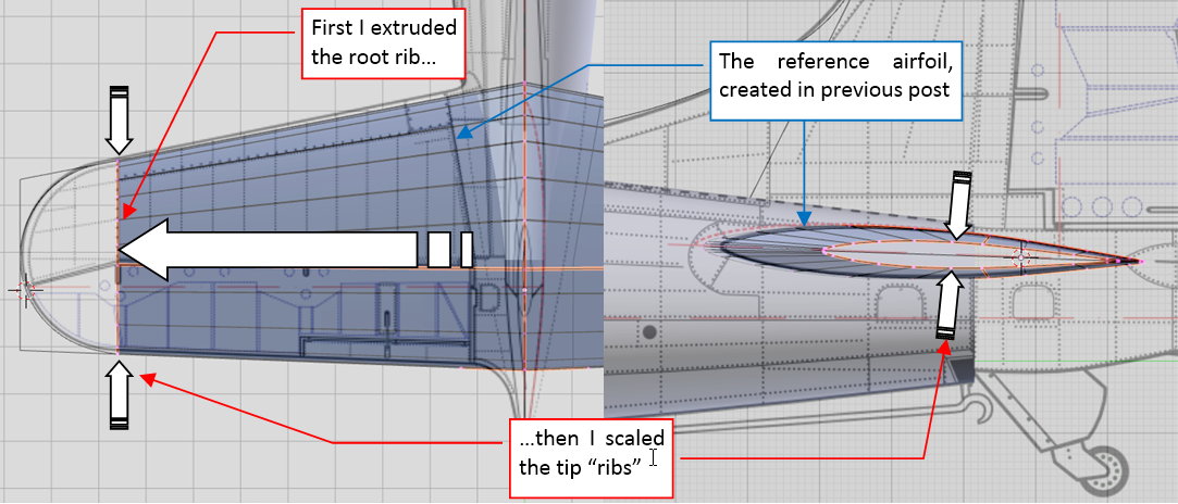
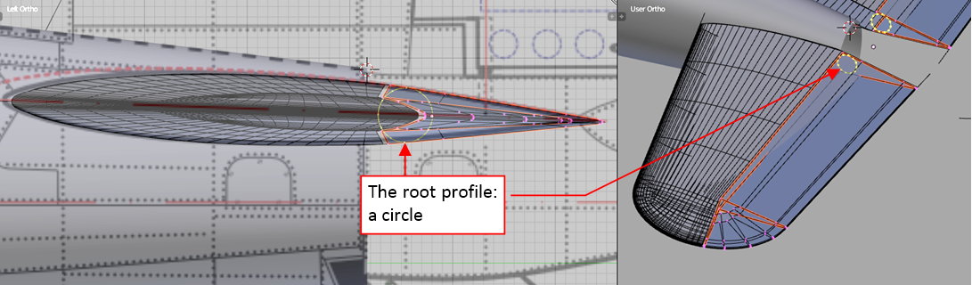
In the previous post I created the reference airfoil of its root rib. Now I copied it into a new object, straighten along the fuselage centerline, and finally extruded spanwise:
I checked the resulting shape, ensuring that the thickness of the tip ribs matches their counterparts on the photos:
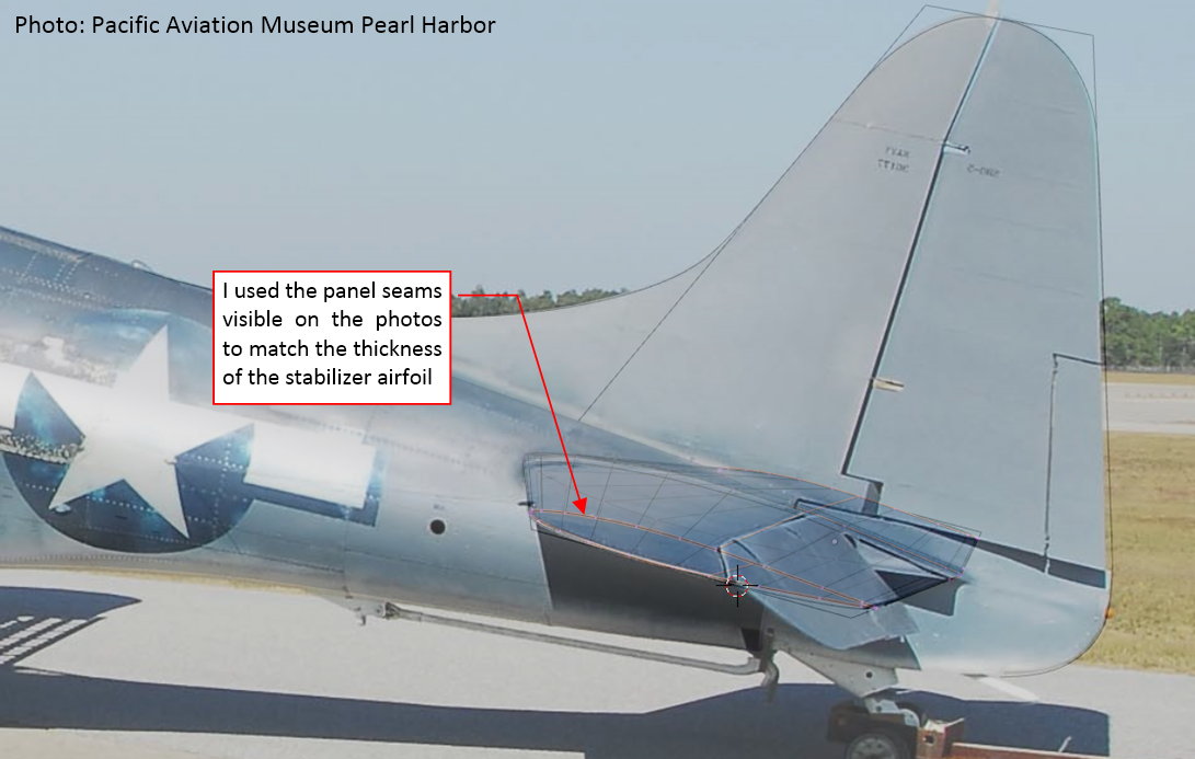
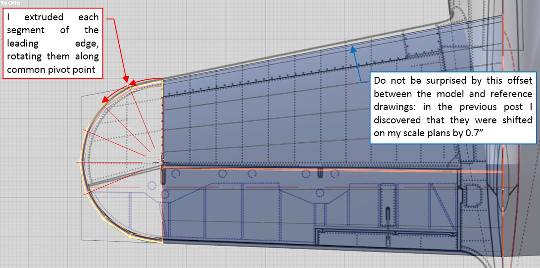
When this base shape was verified, I started to form the curved contour of the tip. Basically, it was an arc, thus I shaped it by extruding and rotating subsequent mesh segments:
Preparing the horizontal tailplane for such a mesh topology, I used the same number of rib vertices to form the leading and trailing edges of its root airfoil.
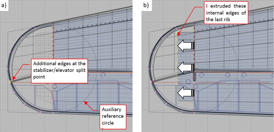
In the next step I created an additional gap in this mesh, at the point where it will be split between the stabilizer and the elevator (as in figure “a” below):
Such a gap deforms the original circular contour of the tip. To restore its shape, I had to move a little two nearest vertices on each side of the gap. Facilitating this task, I used an auxiliary circle as the reference shape.
To fill the empty space inside the tip, I extruded the internal edges of the last rib (as in figure “b”, above).
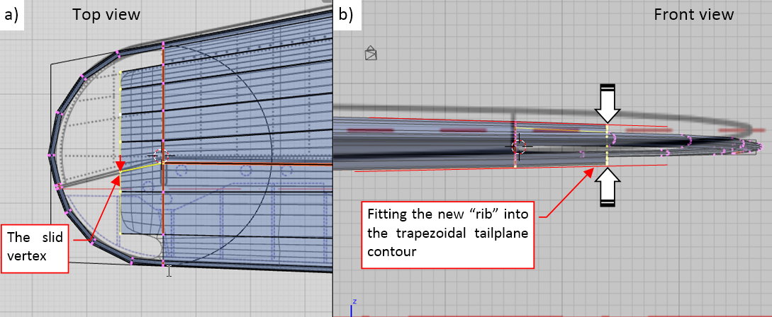
I slid the last vertex of the edge that runs along the elevator leading edge, forming in this way the angle visible on the reference drawings (as in figure “a”, below). In fact, its location was re-checked on the reference photos, thus it lies in a slightly different place than you can see on the underlying scale plans.
Of course, I also scaled the thickness of this newly formed “rib” (as in figure “b”, above), aligning it to the slope of the previous, trapezoidal segment of this tailplane.
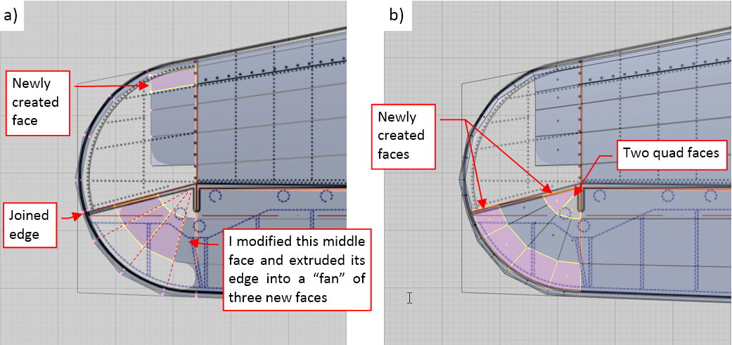
In the next step I started to build different topologies in each part of this tip mesh. In the “stabilizer” part I joined the “tab” of the internal faces and the leading edge (as in figure “a”, below). In the “elevator” part, I removed the first and the last face of this tab, and shifted the vertices of the middle face, forming a thinner trapeze. Then I extruded the outer edge of this face several times, rotating them around the “corner” of the elevator leading edge. Note that each of these faces corresponds to a single mesh segment on the tip external contour:
I also joined the “gap” in the tip contour into a single, “sharp” (Crease = 1) edge. (In fact, I should create it as a single sharp edge in the beginning). Such an arrangement allows me to quickly create an array of new faces that closed the tip of the elevator (as in figure “b”, above). Note that I filled the gap in the “corner” using two quad faces.
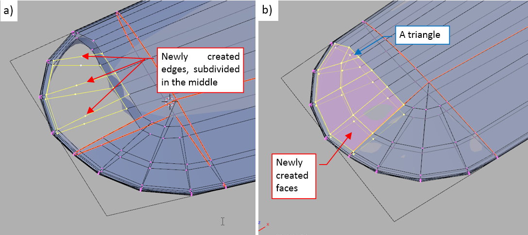
To match the topology of the elevator tip, I had to add additional “rib” to the stabilizer mesh. I did it in three steps. First, I created edges that joined the corresponding vertices of the tip external contour and the internal faces (as in figure “a”, below). Then I split them by half (using the Subdivide command). Finally I used all these vertices to create new faces (as in figure “b”, below):
Note that I had to create a single triangular face near the leading edge (see figure “b”, above). Fortunately, the mesh curvature in this place is low enough that it does not disturb the resulting, smooth shape of the tip.
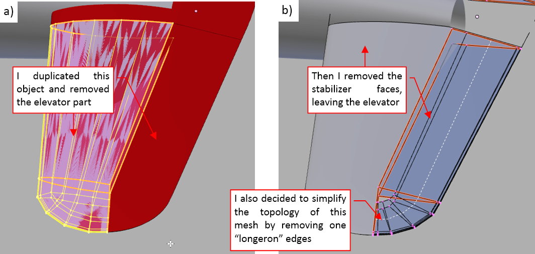
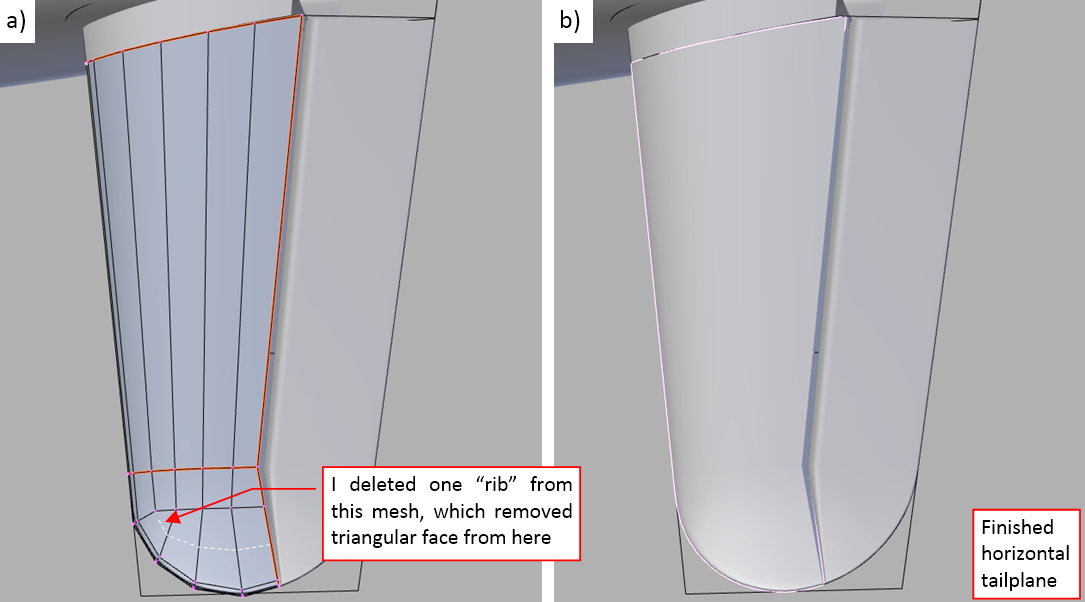
When the overall shape of the tailplane was ready, I split it into the stabilizer and elevator objects. I did it by copying the original object and then removing the “elevator” part of its mesh faces (figure “a”, below):
Similarly, I removed the “stabilizer” faces from the elevator object (see figure “b”, above). Ultimately I also simplified this mesh by removing one of its “longeron” edges. (It seems that the tip contour in the front view requires just a three-point curve).
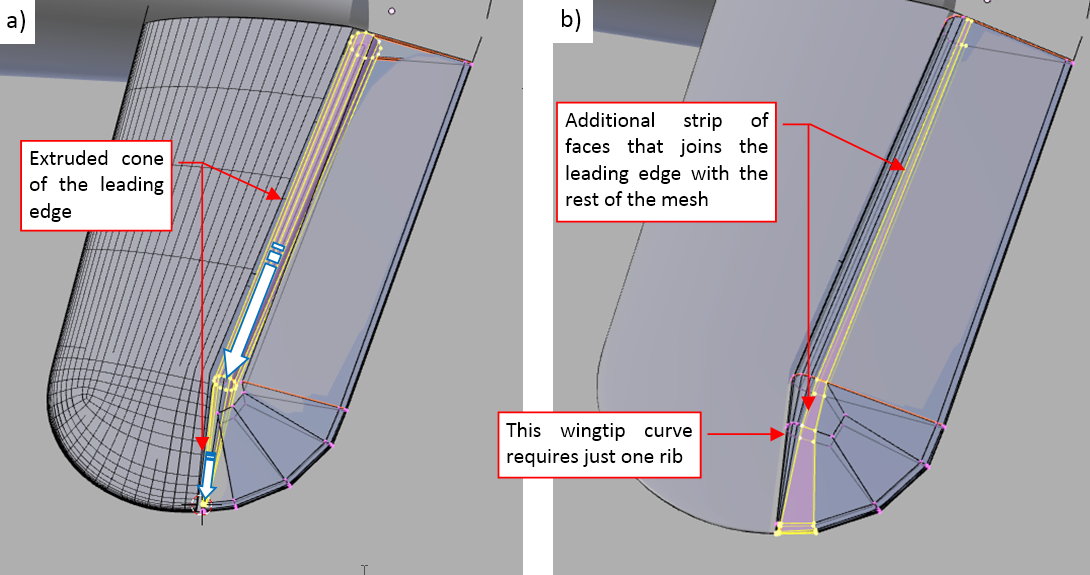
The elevator of the SBD Dauntless had an oval leading edge (it was the aerodynamic compensation, an area shifted in the front of the hinge line). I started to form this element by inserting on the symmetry plane a circle (consisting 12 vertices):
Then I extruded it spanwise, adapting its radius to the local airfoil thickness (as in figure “a”, below):
In the next step I removed the rear faces from the leading edge cone, and joined it with the rest of the elevator mesh (see figure “b”, above).
The presence of a single middle edge in the elevator tip allowed me to remove similar edge from the stabilizer tip (as in figure “a”, below):
Of course, it would be even easier to not create this edge at all — but this is typical situation, when I modify the initial concept of the mesh topology during the progress of the work. Figure “b” (above) displays the resulting tailplane assembly.
In this source *.blend file you can evaluate yourself the model from this post.
In the next post I will describe my work on tailplane fairing.
Very impressive, but I’m not surprised based on your previous works. The SDB is one of my favorite work horses of WW II aircraft. The SDB probably changed the course of the entire war in the Pacific at Midway.
Take care,
Precisely! Thank you, Fred!
OK, back to work:
In the previous post I formed horizontal tailplane of the SBD Dauntless. In this part I will describe how I created the fairing between this tailplane and the fuselage. It is an easier part than the wing root fairing, because it is smaller and most of its cross sections are not circular.
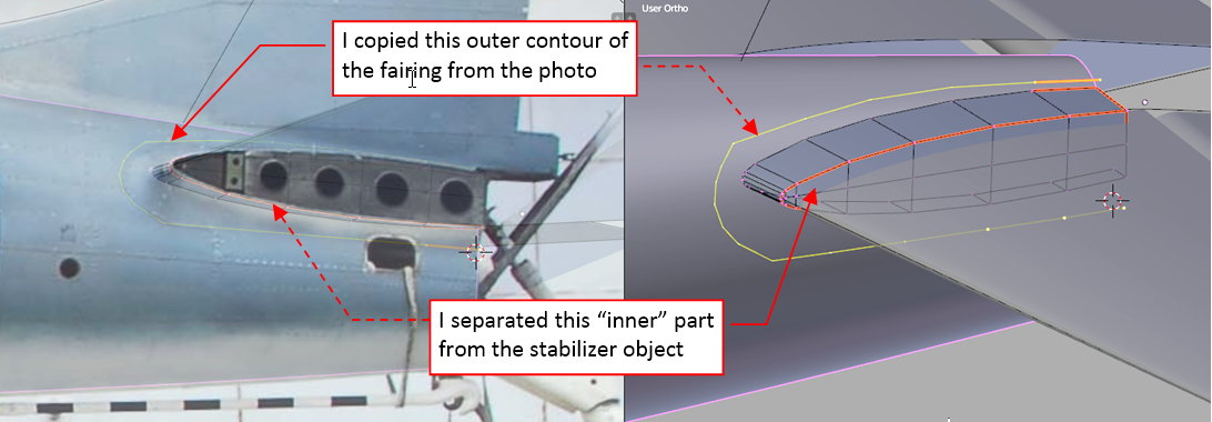
At the beginning I cut out from the stabilizer its middle segment, along the root rib:
Then I “draw” the outer contour of this fairing in the side view. I also checked it in the reference photo (as you can see in the figure above).
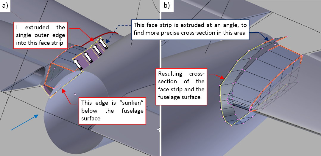
Then I projected this “sketched” outer contour onto the fuselage. I did it by extruding its polyline into a face strip that crosses fuselage surface (figure “a”, below), then finding the intersection edge of this mesh with the fuselage (figure “b”, below):
The intersection edge was calculated by one of my Blender add-ons (named Intersection — you can download it from here). In general, it would be easier to extrude this edge horizontally (because I sketched this contour in the side view). However, I was afraid that the add-on will lost the track of the upper rear part of this mesh (the part that crosses just the upper tip of the fuselage surface). That’s why I initially shifted this contour close to the fuselage, and extruded it in a more-or-less perpendicular direction to the fuselage surface.
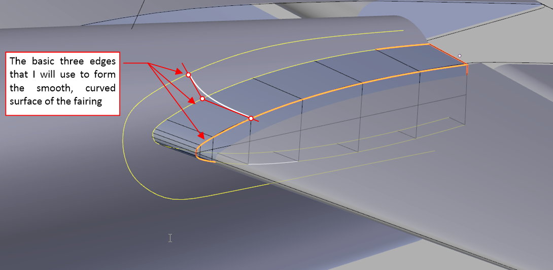
All in all, after this operation I have the three edges, which is enough to create the first version of a smooth fairing:
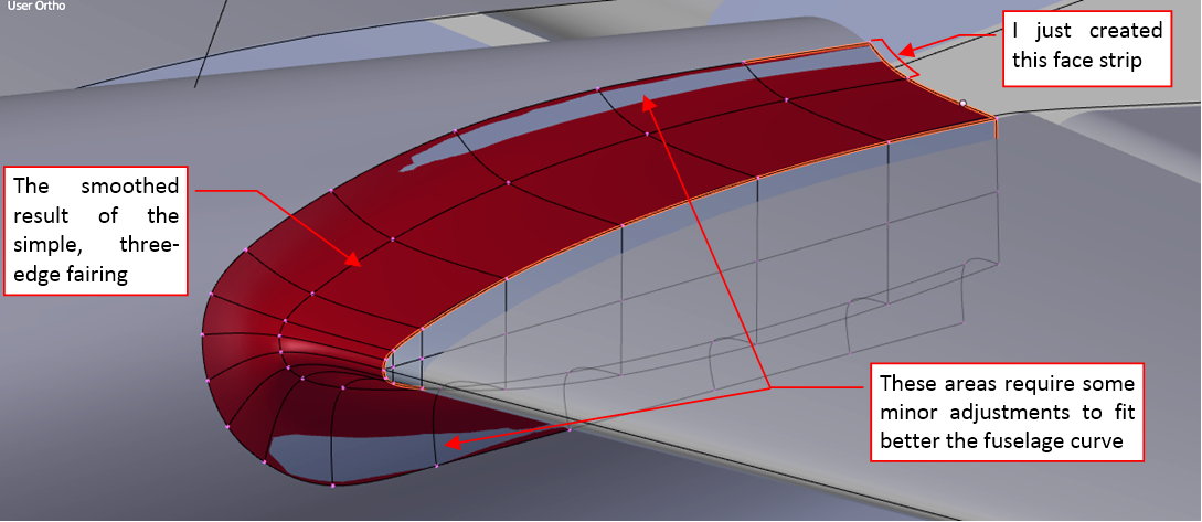
Figure below shows the initial smooth, subdivided mesh based on these three edges:
It starts to resemble the original element. I created here the new row of faces, from the middle edge to the outer contour. Then, before creating this screenshot, I switched the display mode to the resulting subdivision surface.
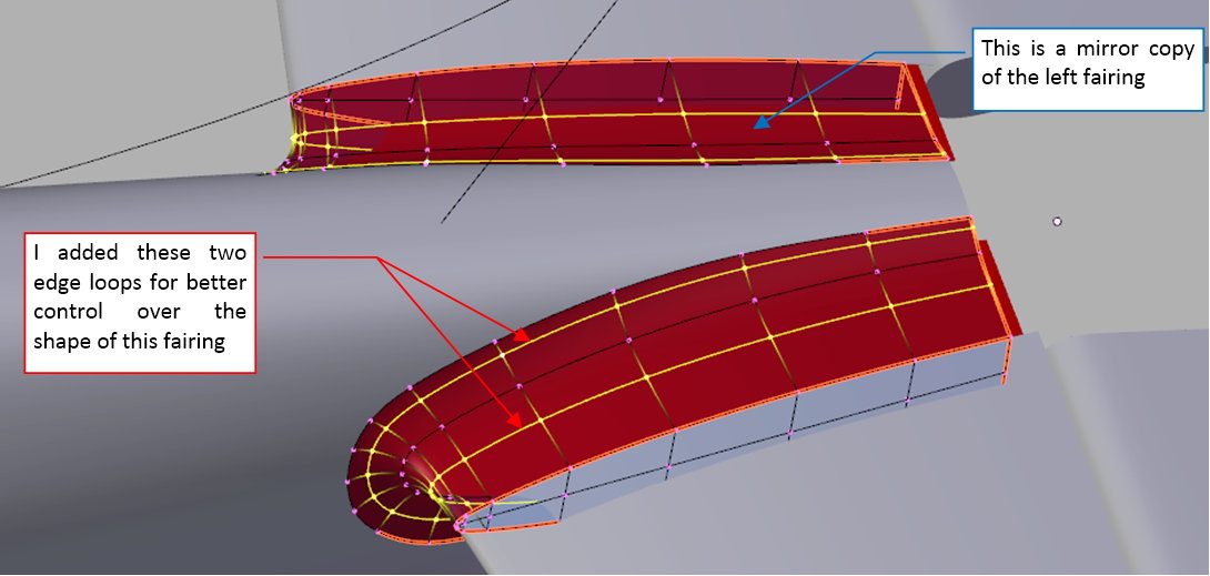
To have better control over the shape of this fairing, I inserted two additional edge loops into this mesh
These additional vertices were extremely useful in shaping the bottom edge of this fairing, which had a semi-circular cross section:
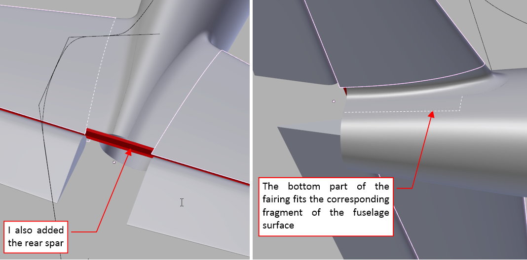
In the most of the aircraft designs the fairing is just a piece of sheet metal bolted over the fuselage skin. In the SBD Dauntless it was an integral part of the fuselage skin (except the area around the stabilizer leading edge). Thus I had to extend the bottom part of this mesh, copying the fragment of the fuselage surface (as you can see in the figure above).
Figure below shows the finished fairing. As you can see, it smoothly fits the fuselage:
It was not necessary, but I also created the rear spar of this tailplane — just because I do not like to see a large empty space in a finished element (the fuselage is not finished, yet!).
In this source *.blend file you can evaluate yourself the model from this post.
In the next post I will create the fin and the rudder.
Thanks for posting this wonderful tutorial. I’m enjoying it immensely, and learning a lot about how to do things in Blender. I can see this being very handy for doing preliminary modelling of things I actually want to build.
One thing I am wondering about is camera angles for overall visualising of models, mainly in terms of correct perspective. Which camera angles and other settings have you found give the closet approximation to the way the human eye would see the same full-sized object?
Thank you very much for following!
When I render a picture of an aircraft, I usually set the Blender camera lens length between 50mm and 80mm. However, I suppose that the lens length of our eyes changes in a dynamic way, depending on the distance to the object we are looking at. (That’s why when we are looking on a flying airplane, it seems much larger than on the photo made using the standard lens. Our eyes switched into their “telescope mode”).
The only advice comes from the Renaissance painters: the focus of the perspective projection (i.e. lens length) depends on the size of the picture frame AND the distance from the spectator who is looking at it. These five points define the “viewing volume”. Thus, if your final picture is reproduced on a A4 page, you can assume that it will be viewed from distance of about 30cm. Using the page width and this distance you can calculate the standard lens length (of a 35mm-wide camera): 50mm in this case. But when your picture has to be placed in one column of a two-column article on an A4 page, you have to render it using two times longer (100mm) lens length.
Final thought: our eyes easily forgive the difference in the picture lens length (you can safely use a 50mm camera for a small picture and nobody will see anything wrong in it). We can see that something is wrong in the picture when you use a “fish eye” perspective, or an orthogonal camera.
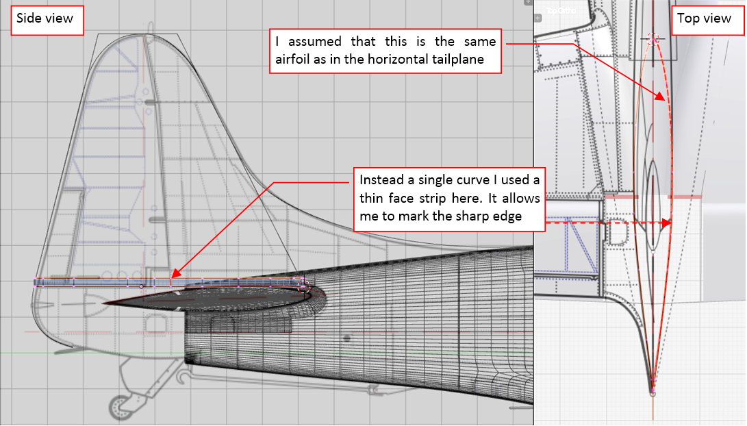
This week I have worked on the SBD vertical tailplane. I started by forming its root airfoil (see the figure below). I had no description nor a direct photo of the airfoil used here. However, the reference photos reveal that it could have similar shape to the airfoil of the horizontal tailplane. Thus I copied that curve into this mesh.
Note that I used here a thin strip of the faces instead of a single curve (which I used in the case of the horizontal tailplane or the wing). The reason is simple: on the single subdivision curve I cannot mark a “sharp corner” at a control point (original mesh vertex). On the face “strip” I can mark the corresponding edge as sharp (increasing its Crease coefficient to 1). I marked in this way the edge at the split between the rudder and fin. Simultaneously I can form such a face strip in the top view as easily as a single curve. (I just have to remember to select its vertices using the group select commands (Border-select or Circle-select), instead of the simple mouse click). Why didn’t I use this method in the previous cases? Well, good ideas require some time to emerge…
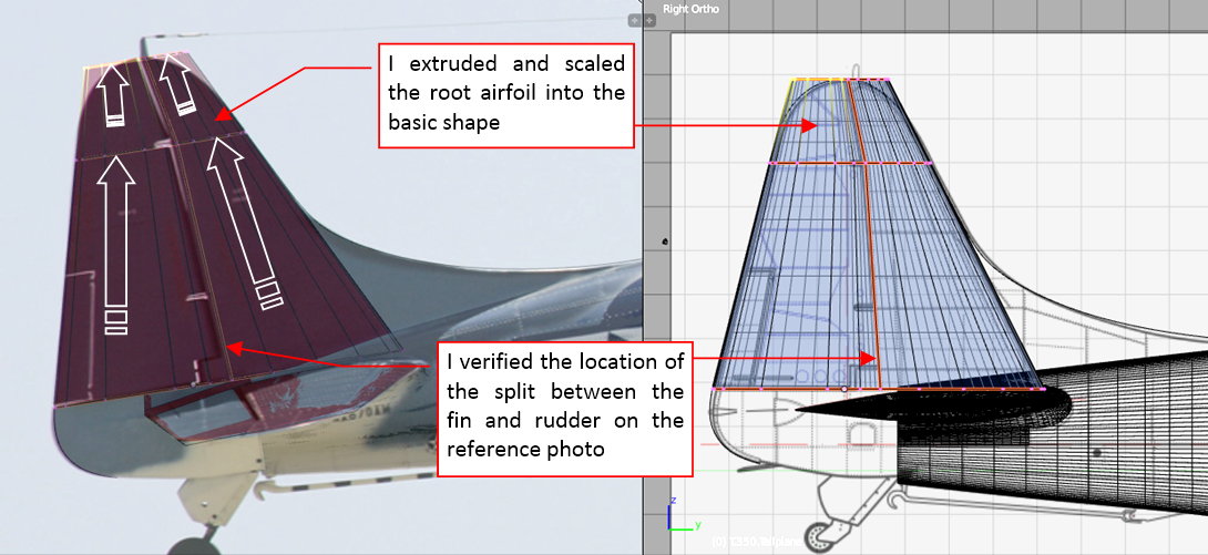
Once the root airfoil was ready, I extruded it into the basic trapeze:
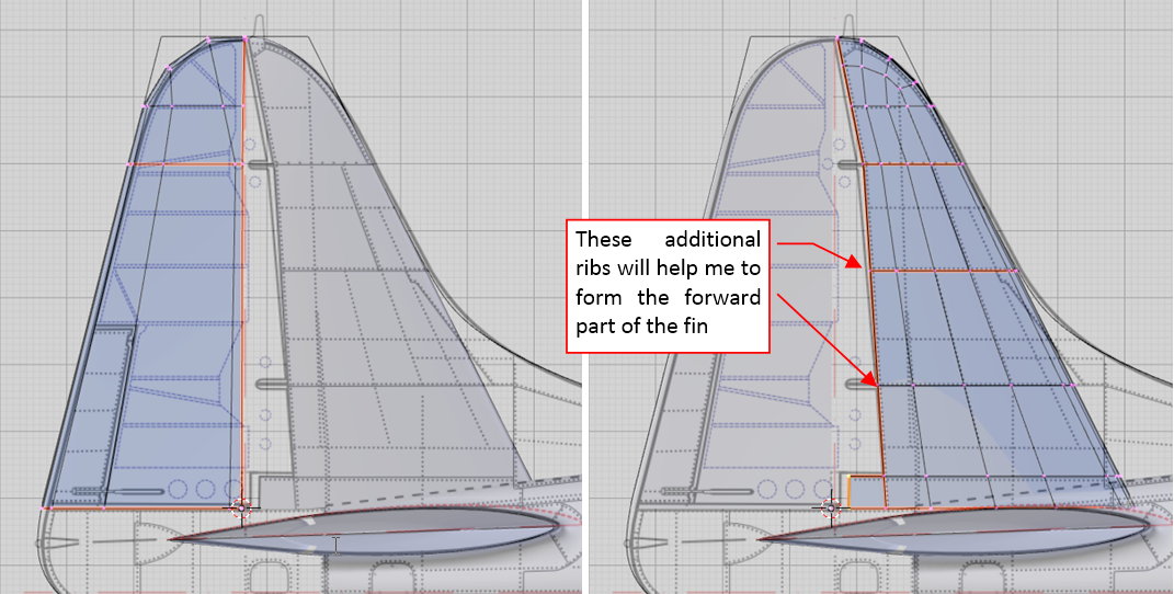
Then I split this mesh into the rudder and fin (i.e. into separate objects, as in figure below):
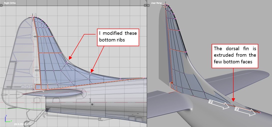
Note that I added additional “rib” edges to the mesh of the fin. They will be useful in forming the forward fragment of this part.
Initially, I extruded the first approximation of the dorsal fin from the bottom edges of the lower ribs:
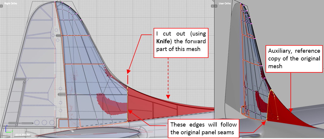
However, I decided that the resulting topology of this mesh differs too much from the original layout of the panel seams (and the original ribs and spars). To make a better approximation, I used the fin shaped in the previous step as the reference object (in the figure below it is in red):
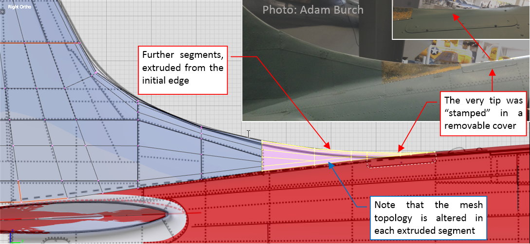
I cut out the forward part of the original fin, forming in this mesh the first vertical edge. Then I extruded it into next segment:
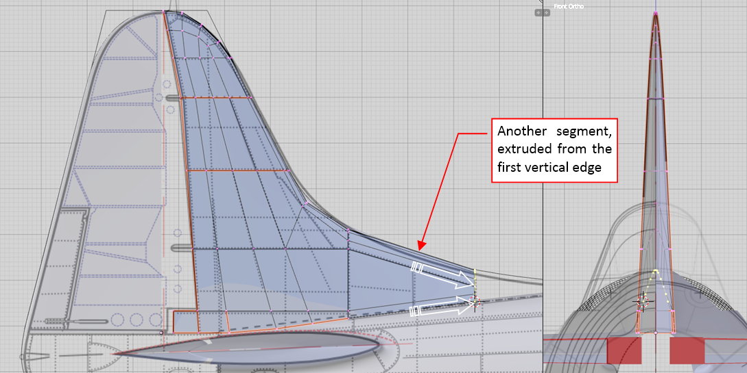
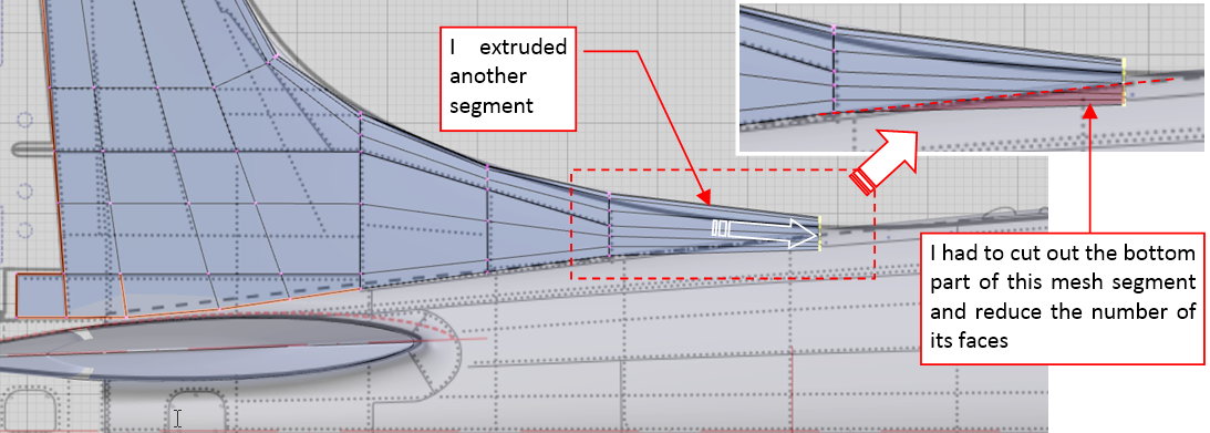
The next segments were extruded in similar way:
In each new segment the vertical cross section is significantly smaller than in the previous one. I had to compensate it by cutting out its bottom fragment (using the Knife tool — as in figure above) and reducing the number of remaining faces.
Figure below shows the resulting dorsal fin:
The tip of this fin was formed in an unusual way — it was stamped in the cover of a fuselage hatch (as you can see on the photo). I will form this cover later.
Figure below shows the objects created in this posts:
You can examine them in this source *.blend file.
In the next post I will describe my work on the fairing of this fin (it seems quite simple, but occurred more difficult than I expected!).
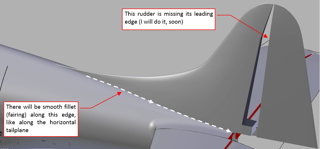
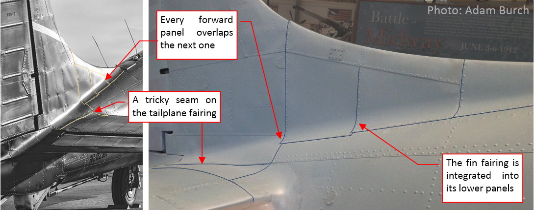
In the SBD Dauntless the fillet along the fin and the fuselage was formed from the bent bottom edges of the fin panels. I am showing it in the figure below:
(To make some of these panel seams more visible on thee photos, I sketched along them thin lines). You can observe that each fin panel overlaps the next one, starting from the tip stamped as the part of one of the fuselage doors (see the second-last figure in the previous post). The outer contours of these panes are not perfectly aligned: you can see small overlaps on the photos (see the figure above). Surprisingly, such a detail makes the modeling more difficult. However, the most difficult part will be the seam between the fin and the horizontal tailplane fairings (as in the figure above). It runs along the fuselage longeron, across the fillet between the stabilizers and fuselage.
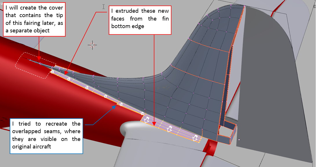
Well, I started this fillet by extruding some faces from the bottom edges of the fin mesh:
As you can see, I already recreated the sharp panel corners in these extruded faces. Then I lowered their outer edges and aligned them to their contours on the top view:
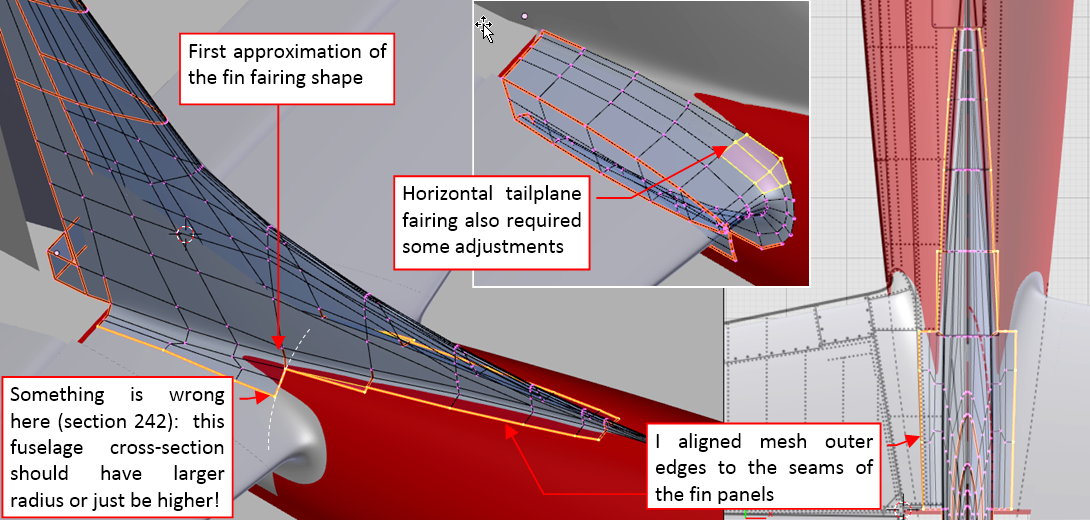
This is the first, rough approximation that fits these panels to the fuselage surface. In this process I discovered that I had to make some modifications to the upper part of the tailplane fairing. However, I was not entirely satisfied with the result: comparing to the photos, something was wrong at station 242 (see the figure above). The outer seam of the fin fillet should be a little bit wider here!
After some additional deliberations I decided that the fuselage under the fin was somewhat higher (by about 0.5”) than on my reference drawings, and the upper arc of these bulkheads had larger radius. Thus I had to modify this part of the fuselage:
I rotated a little this mesh fragment, then scaled up the upper part of each of its three bulkheads.
I had no photo of the SBD fuselage without the fin, taken from the side. In fact, the shape of this fragment on my scale plans is in 80% my assumption! Such small anomalies as this one helps me to discover the real shape of this airplane.
Basing on the corrected fuselage, I was able to fit better the outer edges of this fin to the fuselage and the tailplane fairing:
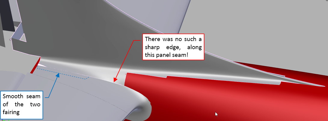
However, I was not satisfied with the forward part of the seam between these two fairings: despite all my efforts, it looked a little bit sharp!
Ultimately, I had to reshape a little bit the tailplane fairing and cut out the excess of its surface along this seam using a Boolean modifier:
This method produced results that resemble the smooth shape that I can see on the photos:
However, I do not like such a “Boolean – based” solution. It seems too complicated. In the next post I will try to eliminate such a “hard” seam between these two panels. I think that much better solution here will be a continuous, smooth surface. The seam can be recreated later, using textures.
Anyway, in this source *.blend file you can evaluate yourself the model from this post.
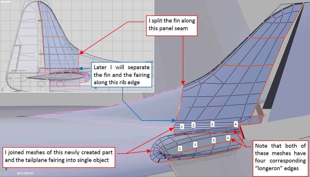
After the previous post I decided to simplify the empennage fairing. Originally I created it from two separate objects: the fin fairing and the tailplane fairing, split across their fillet. Now I decided to eliminate this troublesome seam by joining these two meshes into single object:
I will split it later, along the bottom rib of the fin (there was another panel seam in the real airplane). To simplify creation of the original overlapped panels, I simultaneously split the fin into the forward and the rear part, along one of the original seams.
As you can see in figure above, there are the same number of spanwise edges on both fairing meshes. It is a matter of sheer luck, but it makes the process of joining these two parts much easier.
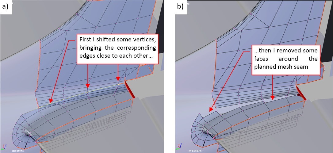
First, I modified these edges, bringing them closer to each other. (I did it by sliding their vertices along perpendicular edges — as you can see in figure “a”, below):
Then I removed the unnecessary faces (as in figure “b”, above).
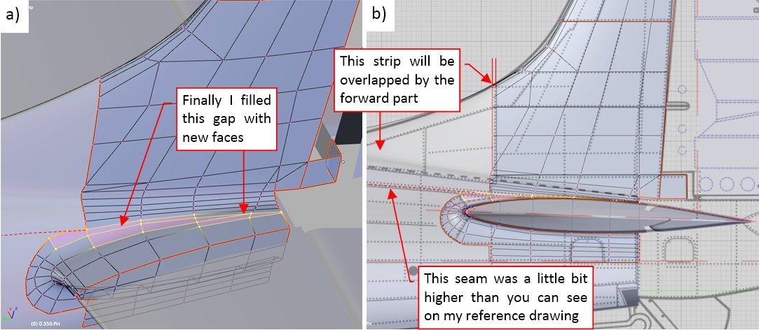
Finally I filled this gap with new faces, effectively merging these two meshes (figure “a”, below):
In the side view (as in figure “b”, above) you can see that the forward part of the fin extends a little the panel line visible on the reference drawing. It will be overlapped by the forward part, which will end precisely along the original seam. (Such an overlap is visible on the photos). Note also that the seam along the fuselage upper panel (marked on the drawing by the dotted line) is somewhat higher than on my scale plans. This is the effect of the modification that I made in the upper part of the fuselage (described in my previous post). My reference drawings are simply wrong about its location in the side view.
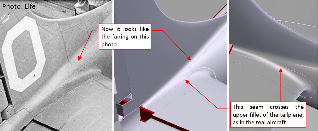
I think that the empennage fairing looks much better after this modification:
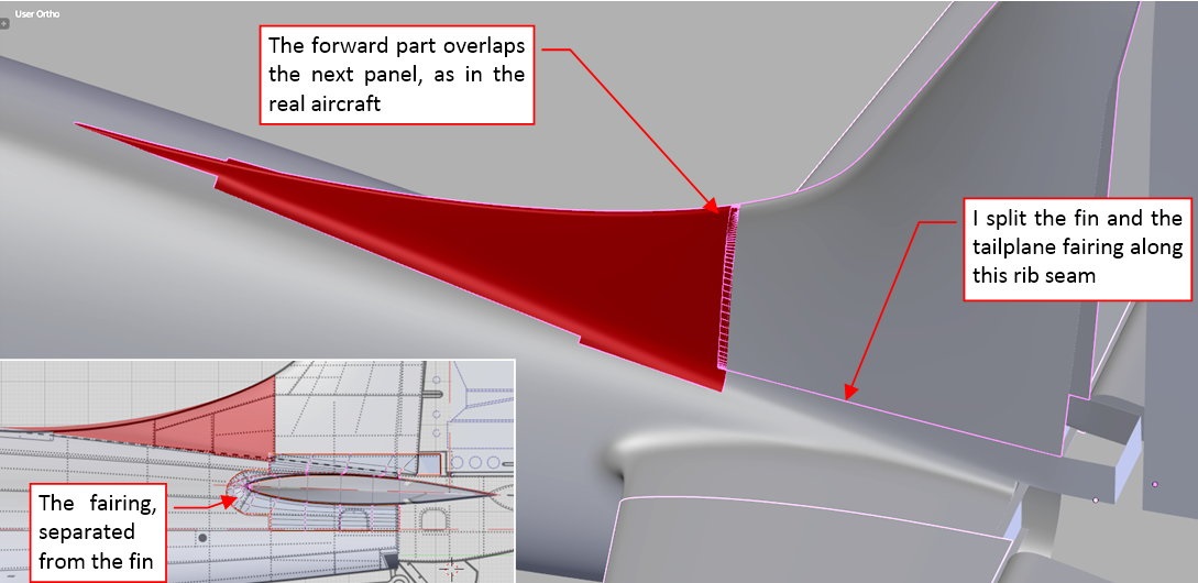
It fits well all the three elements it joins: the fuselage, the fin and the tailplane. The fillets looks smooth and natural. As you can see, I split the fin and the fairing along the bottom rib edge, as I planned. (There was original panel seam). I think that this new arrangement of the model objects will facilitate further detailing of this assembly (for example, now the forward fin panel overlaps the other elements, as in the real airplane).
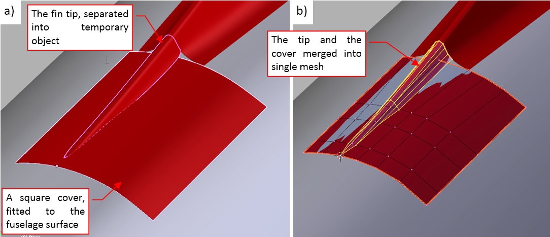
The last element of this assembly is the fin tip: in the real airplane it was stamped in one of the fuselage inspection doors. I started to form this part by creating a plain, rectangular cover placed over the fuselage, and separating the corresponding fragment of the fin tip (figure “a”, below):
Then I joined these two object into a single mesh (figure “b”, above).
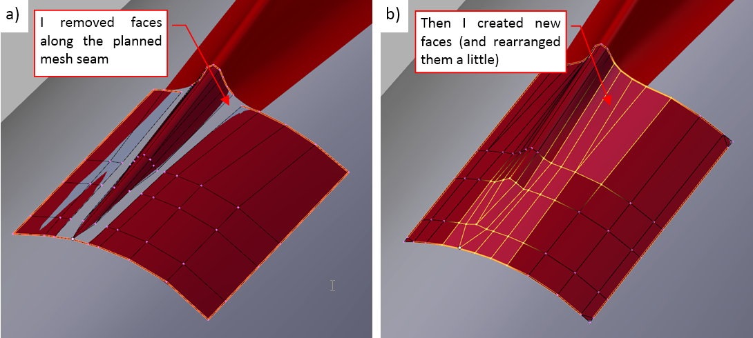
In the next step I adjusted corresponding edges of both elements, and removed the unnecessary faces (figure “a”, below):
Finally I filled this gap with new faces. Finally, after some rearrangements of the mesh topology, the resulting elements looks like in figure “b”, above).
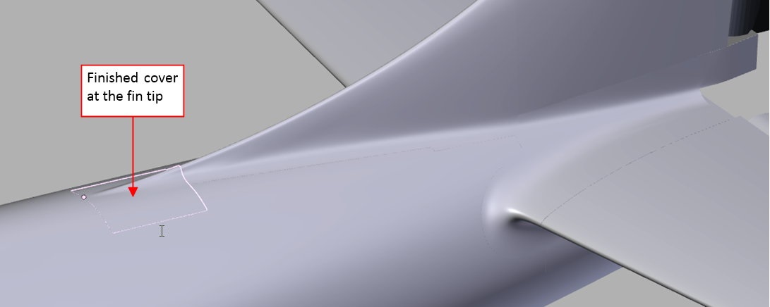
Figure below shows the final object, fitted to the fin and the fuselage:
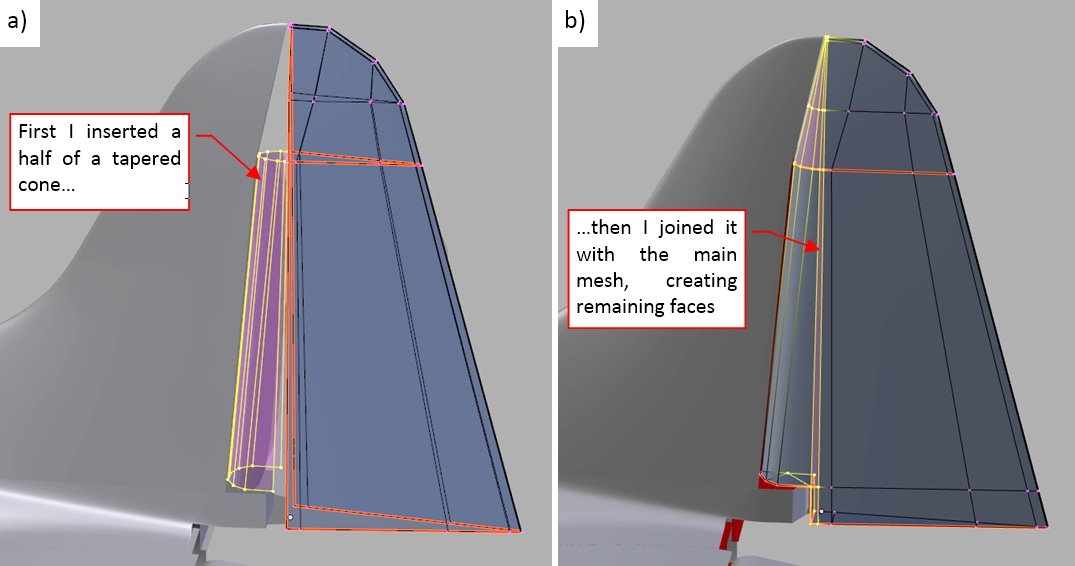
The last element that I need to finish in this empennage is the rudder leading edge. I created it in the same way as the leading edge of the elevator: from a single circle (see my post from January 9th). I extruded it into a cone (figure “a”, below), then removed the unnecessary faces and created new ones (figure “b”, below):
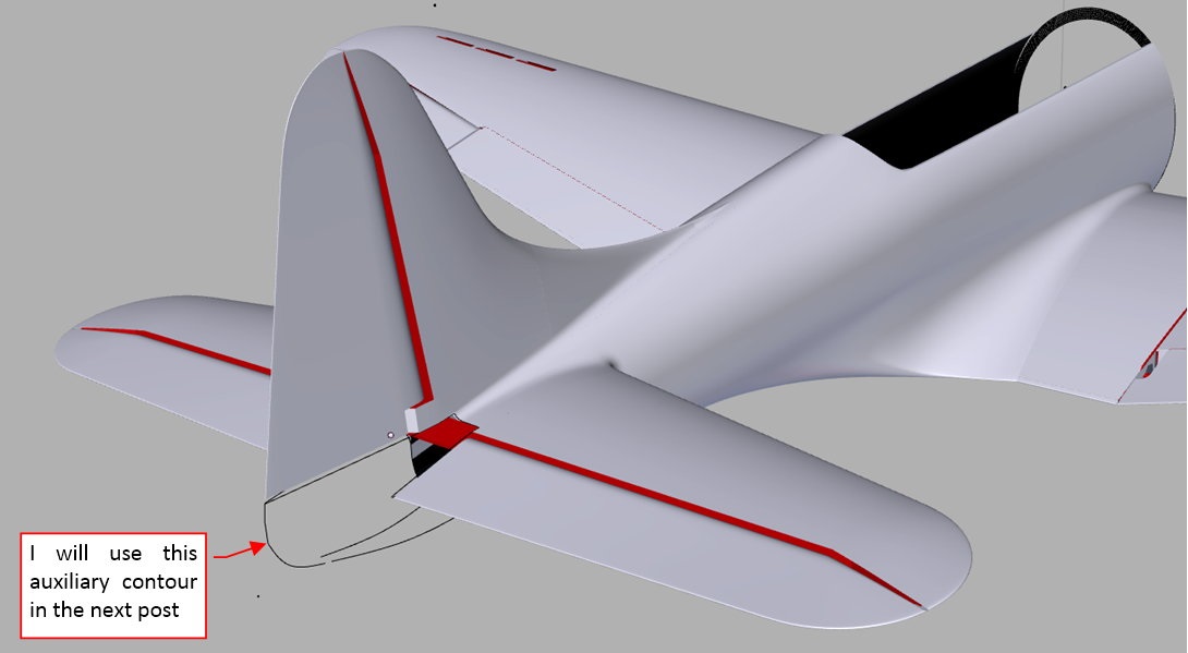
Figure below shows the completed empennage (note that I also created the fin spar):
The last missing element is the tail tip. It has a rather complex shape, so I started modeling this part by copying its outer edges from the fuselage, fairing, rudder and elevator. You can see them in the picture above. I do so when I have no clear idea how to start. In the next post I will describe what I did next.
In this source *.blend file you can evaluate yourself the model from this post.
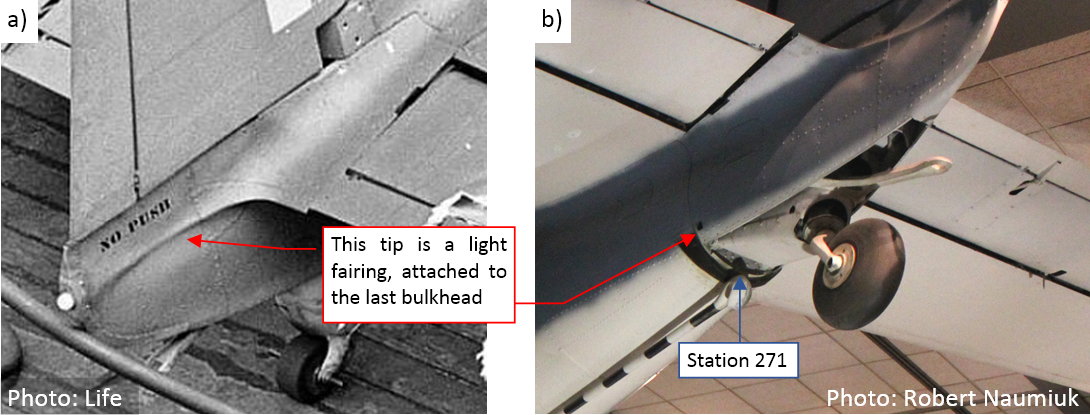
The tip of the SBD tail was a light fairing, attached to the last bulkhead (at station 271 — see figure “b” below). That’s why you can see “NO PUSH” label on the photo in figure “a”. The tail wheel was attached to the bulkhead 271, which transferred the resulting loads forward, via the tail structure. The tail tip fairing was always free of any significant loads. However, the shape of this part is a combination of the empennage fairing and the last fuselage segment. What’s worse, there is a large opening at the bottom — for the eventual tail wheel deflection:
I had no initial idea about the mesh topology that I should use for such a part. Thus I started by copying all of its external edges from the adjacent objects (see figure “a” below):
Then I worked out an idea of its topology by sketching possible mesh edges on a scrap of paper. (I often do that before I start modeling a complex mesh). You can see the scan of my sketch of this tip in figure “b”, above. I “think by drawing”, so this method helps me to better realize the shape that I have to create. These working sketches object do not have to perfect. The more important thing is the order of the individual edges and vertices (identified by the numerical IDs).
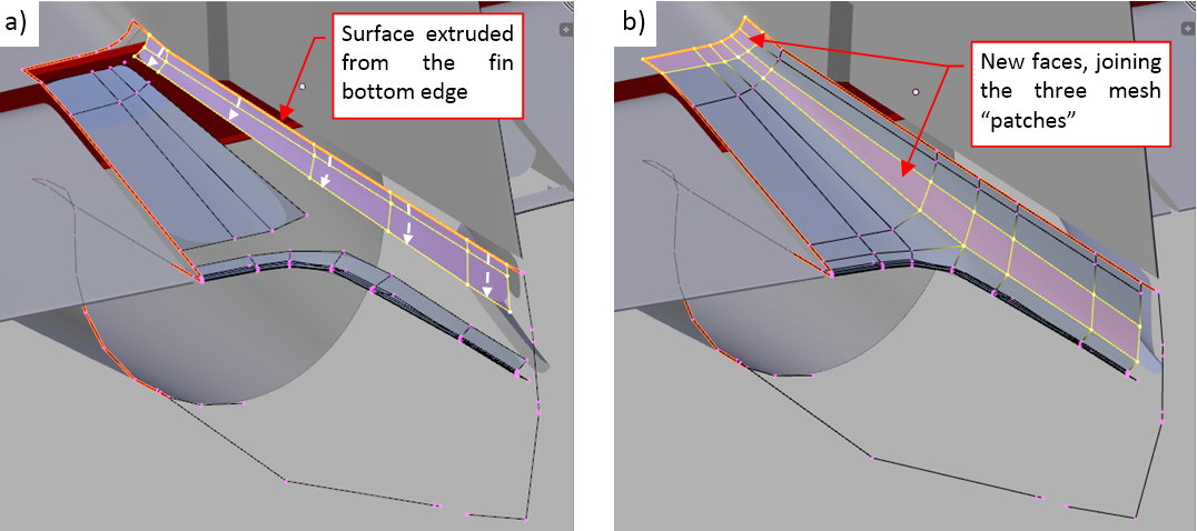
When the mesh topology on the sketch looked simple enough, I started building this mesh by extruding the trailing edges of the elevator fairing (see figure “a” below):
Then I extruded the upper edge of the elevator fairing into another rectangular “patch” (see figure “b”, above). In the next step I extruded similar “patch” from the rudder contour (see figure “a”, below):
Finally I filled the gaps between these three mesh “patches” by creating two rows of new faces (as in figure “b”, above).
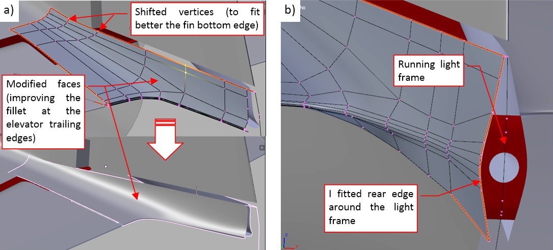
The resulting subdivision surface required some minor adjustments of the control mesh vertices. They formed the proper shape of the mesh behind the elevator trailing edge (figure “a”, below):
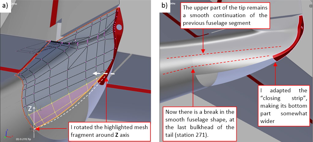
While sketching this tip, I decided that it will be better to close it with a separate object — the “closing strip”. Such a strip reproduces the original piece of the sheet metal that contained the frame of the running light. (I thought that the side-view contour of this tail tip might require different edge distribution than the mesh of its sides). At this moment I created the initial segment of the “closing strip”: the part around the running light frame. Then I used it as the reference object for shaping the mesh of the tip sides (see figure “b”, above)
I split the model surface into separate objects when I expect significant differences in their mesh topology. I “mask” outer edges of such objects by placing them along the original panel seams.
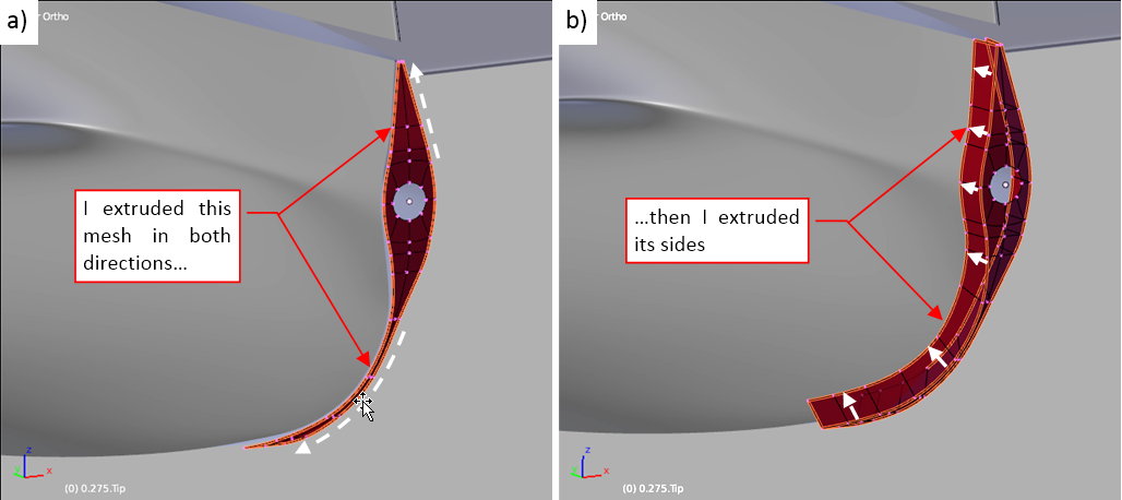
When the upper part of the tip was ready, I started forming its bottom part. As you can see in figure below, I did it in the same way as the upper fairing. First I extruded a part of the bulkhead contour (figure “a”), then I created new faces to incorporate this patch into the main mesh (figure “b”):
I extruded the side faces of this tip from the bulkhead edge (figure “a”, below), then filled the gap in the resulting mesh by creating a row of new faces (figure “b”, below):
(Note that I had to create more “bulkhead” edges in this mesh than I originally sketched (see the second figure in this post). Some of these edges came from the original vertices of the elevator edge, while the other were required by the shape of the bottom edge (around the tailwheel opening).
The ultimate number of edges in a mesh is often the sum of the vertices required to obtain appropriate shape on its opposite border edges.
Finally I extruded and merged the last part of this tip:
As you can see in figure “b” above, I added an additional, diagonal edge below the trailing edge. I did it to obtain a better shape of the elevator fairing
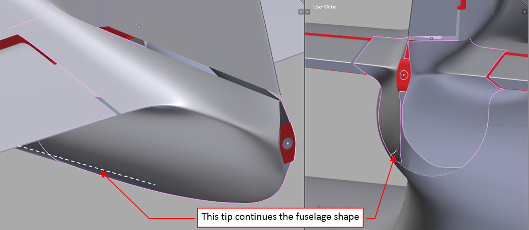
Figure below shows the smooth resulting shape:
I had no photo taken from the top or the bottom that would precisely reveal the vertical contours of this part. Thus I assumed that this tip is a smooth continuation of the tail cone (as I marked with the dashed line in Figure 38‑9). In the next post I will verify this assumption using available photos.
In this source *.blend file you can evaluate yourself the model from this post.
How did you get the various bits to extrude along the lines you wanted them? For example, the “extruded last fragment” in figure a) just above.
Well, of course this requires a sequence of several steps:
[SUB]
(I decided skip these details in the previous post, beceause they would require additional pictures. The “narration” in this thread is less detailed than in my book, where I described all of such basic steps).[/SUB]
In the previous post I formed the shape of the SBD Dauntless tail tip. In this post I will finish its “closing strip” that contains the running light frame. I will also verify the overall shape of the tail tip using the available photos.
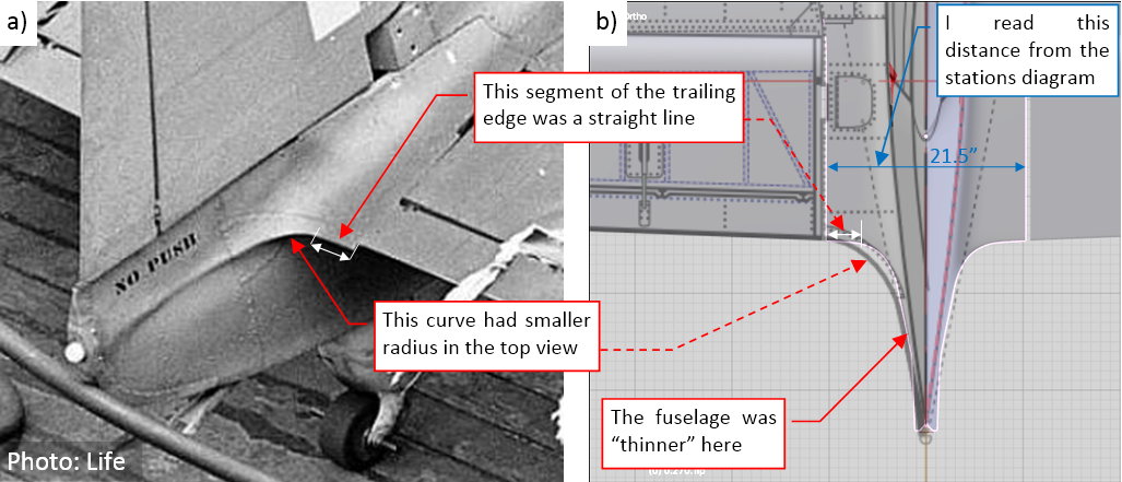
There is one thing I didn’t mention in the previous post, just to keep the narration focused on the pure modeling. Before the modeling I carefully studied the reference photos. In the result I found differences in the shape of the curved trailing edges of the fairing behind the elevator. On the photos you can see a straight fragment of this edge (figure “a”, below). Its presence means that the curve of the trailing edge was smaller, and the fuselage was somewhat thinner here. You can see the differences between the real shape and my reference drawing in figure “b”, below:
I did not notice these detail before. As you can see, I applied this modification when I started to model this part.
When the mesh of the tail tip was formed, I worked on the “closing” strip. I created a part of it as a separate object in my post from 2016-02-13. Now I extruded it along the side contour (see figure “a”, below), then extruded the side faces of this strip (figure “b”, below):
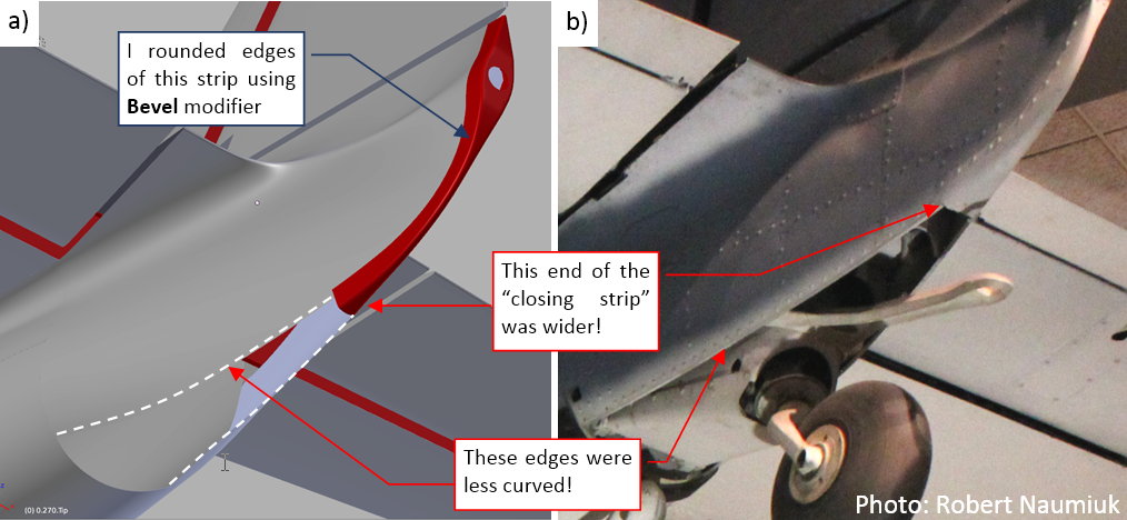
I rounded the sharp edges of this element with a fillet. It is dynamically generated by a multiple-segment Bevel modifier — you can see the result in figure “a”, below:
However, when I compared the bottom part of this tip to the photos, I saw that there are significant differences! Jut compare it in figure “a” and “b” above. The side edges of the tailwheel opening are less curved, and its rear edge is wider.
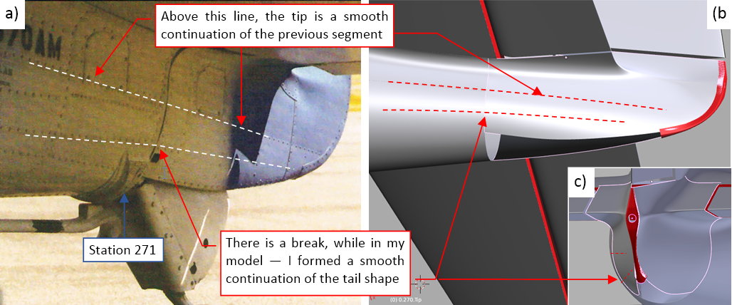
What is the reason of these differences? So far I tried to shape the bottom part of this tip as the smooth continuation of the previous tail segment (see figures “b” and “c”, below). It seems that I was wrong: these lines were broken at station 271, where the tip fairing was attached to the last bulkhead of the tail (see figure “a”, below):
To correct this shape, I first made the tailwheel opening wider by rotating the bottom part of the mesh:
Finally I adjusted the shape of the “closing” strip to this new opening (figure “b”, above). Now it resembles the original in the photo.
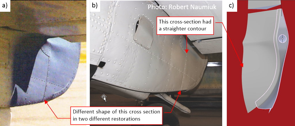
When I fixed the shape of this opening, I noticed another difference, this time in the shape of the tip cross-section. It is revealed by the vertical panel seam behind the tailplane:
This vertical seam seems to be flat, especially in the restored SBD from figure “b”, above. In my model this line is much more convex (figure “c”, above).
The primary reason of all these differences between my model and the real airplane is the lack of the reference: I have no photos of this fuselage tip taken from above. Thus I have to determine its shape on the plans by various indirect means — and assumptions. In such cases, when you shape it as a 3D model, you will often find errors in the reference drawing.
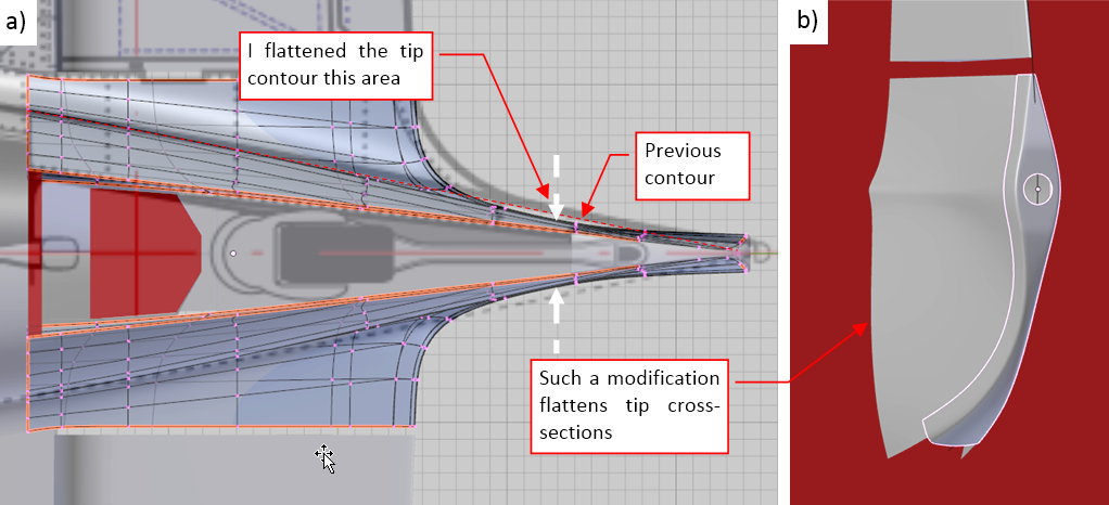
Well, to make this section more “rectangular”, I have to make the fuselage even thinner in this area:
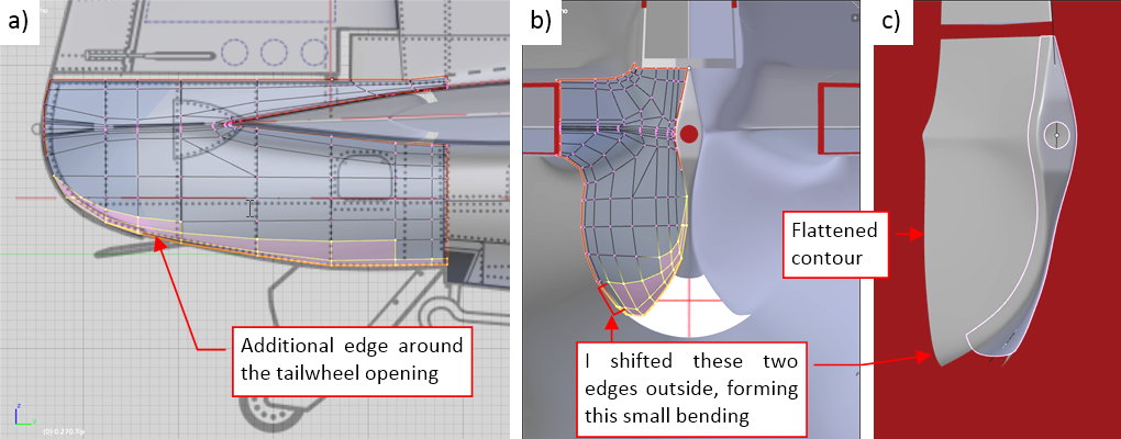
Yet the photos reveal another small difference, this time between the two different restorations of the SBD Dauntless: compare the photos “a” and “b” in the second-last figure above. The aircraft from photo “a” has the edges of the tailwheel opening bent inside, while in the SBD from photo “b” the tip cross-section contour is straight to the end. Which one is true? At this moment I do not know! However, it will be better to modify the mesh of this tip in a way that makes such a rounding possible. (You can always straighten a curved surface. However, bending a flat mesh requires additional edges). That’s why I modified the mesh topology around this opening, adding another “longeron” edge (figure “a”, below):
Then I shifted two bottom edges a little (figure “b”, above), forming such a cross section as you can see in photo “a” (compare it with the shape in figure “c”, above).
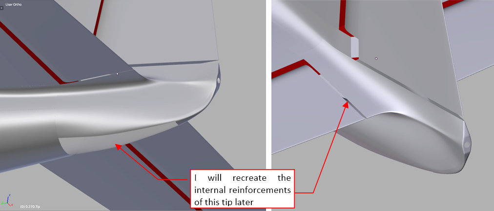
Below you can see tip, finished for now:
I will recreate its internal reinforcements (bulkheads, stringers) later, during the detailing phase. At this moment I do not know whether I have to modify this part in the future. (It may happen when I find a better reference materials). Such a modification would require adjusting these internal structures, so it is better to postpone their creation as long as possible.
In this source *.blend file you can evaluate yourself the model from this post.
In the next post I will start to work on the engine cowling.
Your work is awesome. I am sorry that I haven’t commented on the last updates, but it feels so repetitive as the quality is very high everytime!
The level of detail is impeccable… I’m still looking through the images where you’ve aligned the wireframe with the photo. In awe… Neat stuff, any idea what time-frame it’ll take to complete the HP model?
thorst - thank you for following! (I know that it would be a little confusing to post repetitive comments :)). Within two-three weeks I am going to try flattening the barrel distortion in some of my reference photos (I still encounter the problems with their geometry that you have described). I tried the Hugin software, but for this purpose it requires at least two similar photos. I decided to use a simplified method: teh Lens Distortion filter in GIMP. I will report the results.
Netroxen - thank you! I am going to finish this model in December 2016. (I plan to model many of its interior spaces: not only the cockpit, but also the engine and the whole skeleton - all these ribs, bulkeads, longeron, stringers…)
Witold, if you should have an extensive walk around of one specific machine (>50-100 images), you could try VisualSFM and CMPMVS, both are photogrammetry tools. The second one needs the output of the first, and will automatically determine the camera position and focal length, and it also produces distortion corrected versions of the input images. But it needs good coverage of the object to be analysed.
Hi @Witold, long time no see!
Anyway, this is by far one of the best work out there (I’m surprised you don’t have your 5 stars yet)…I admire your dedication and level of detail.
As for me, I haven’t touched the F-16 since last year and I don’t have much time to dedicate to carry on working on it at the moment, the only time that I have worked on it took me around a couple of hours to get back on the groove of working in Blender :(…but don’t fear as I’ll be posting some work that I did last week on it.
Thanks for this tip! Unfortunately I do not have such large series of the photos, so I will try to use a certain approximate method (I will describe it later).
Hello tommy1441! I am counting on your F-16 thread! As for this one - the stars in this section of the forum are given for stunning results, while I am producing here just a decent work, so far. Maybe the visitors will rank me better when the model receives more details :).
[SUB](post duplicated - due to connection problems)[/SUB]