cool result!
Really cool!
Could you also show the UV layout on the image? It looks so beautifully simple.
Thanks
You can clearly see the seams on the wireframe image.
So, I mostly used reset under U panel-menu
This places quadsmone on top of the others. Selected this stack and placed it on the are I wanted, on the posted already displ+AO maps. Simple. No “follow active quad” this time.
I mean, a grab screen doesn’t show much. In this case.
Still keen to see the UV position on the map. Would like to see how the edges lie on the image to achieve this streamlined effect.
The beauty is in the simplicity.
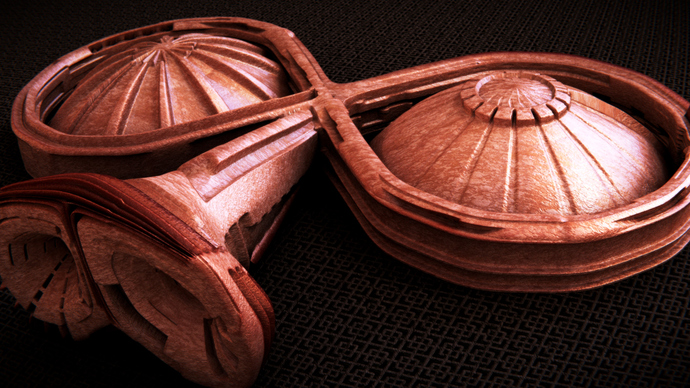
To me it resembles some high-end speaker panel, definitely a change from the usual sci-fi greebled constructions and an example of how this technique can be used for a more subtle effect.
I wonder how much that thing would cost in real-life?
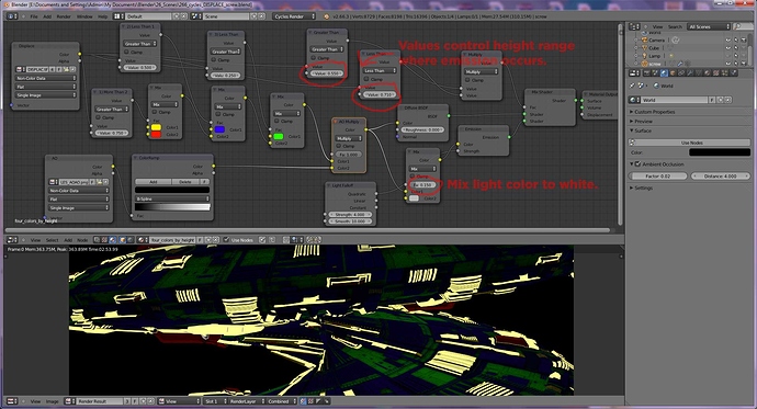
I have extended the four-color-by-height material to include an emission range. These two images show the result of altering the Greater Than and Less Than ranges for Emission. I have also added in a Color Mix so you can mix white, or any color, into the resulting Emission color.
Attachments
@JoHal: Your Welcome!
I started playing around with trying to understand how weight painting effects the displacement. When I read Michalis first mention of it I kind of moved on and did not think about it any more. Then I discovered I was adding multiple displace modifiers referencing different vertex groups to try and control tapering geometry. I just did not make the connection that weight painting creates vertex groups. Not only does it create vertex groups but it allows you to scale/weight those vertices within the group. So by using weight painting you only really need one vertex group and one displace modifier. Use the weight color to reduce or increase features in your model that need reduction or emphasis.
My attempt at trying to recreate Michalis cylinder posted on page 22:
Attachments
Ah, sorry about that Tungee. I guess I read it in Michalis’ cylinder page first. There are so many pages to read…
I put together a short little video to show how I made the cylinder.
I made an attempt to convert this text description into a working scene and shaders. I have updated my previously posted scene with new shaders and setup for Cycles instead of Blender Internal.
First complete baking in Cycles.
AO map and displacement map this way:
Orthographic camera. It’s easy but a little tricky. The distance is critical for good baking.
Assign the following shader to all elements:
Camera attributes / zdepth / (math)subtract / emission BSDF / output.
Under scene properties, linear color space.
16 bit output, save as B&W tiff.
Delete this shader and add a new simple one. Diffuse BSDF/output. Delete all lights, use a grey background at value 1 under environment nodes. Render the AO map. You gonna need lot of samples ~600, so expect long time rendering ~10 mins for a 2048x2048 map.
Again save as B&W 16 bit tiff, linear color space.
I made a guess at the camera distance. I set it to 10, for my scene. I based this decision upon the fact that my camera was 10 units away from the 0,0,0 ground plane.
Hopefully this can help others who want to make their own maps to drive displace. Simply place your own geometry within the FOV of the camera and render out your maps. There are two scenes in this BLEND file. So you need to render out each one to generated a matched set of Displace and AO maps.
Attachments
266_cycles_displace_map_setup.blend (234 KB)
Now that I have a camera setup that can generate displace and AO maps I wondered, what kind of geometry should I place between the camera and the floor?
I revisted the Shipyard files posted on Blendswap and brought in a few of the boxier type ship elements. I scaled them very flat and placed them in front of the camera. Creating a useful displace map with nice features that work together can take a lot of time. But there are already some nice nurnie/widgets out there that we can make use of for map generation.
After rendering the displace map I used the displace map on one of the shipyard shapes for the following result.
Attachments
That’s awesome! I’m inspired once again.
Had some time to dive into some UV’s fun…
Here is where it is so far, lots more I could still do to it. just need more fun time :evilgrin:
Cheers,
~Tung
Hi, thought I’d give a go at this. So here is my attempt using a plane.
But, when I did the same using a different shape (see below) it didn’t work. Here are my steps.
- I created the basic shape (Image A)
- I unwrapped using “Follow Active Quads”
- I applied the Subsurf and Displacement modifiers
- Added a “mapping" node to scale down the size of the .exr map.
The ship is showing no details! 
Click to see large version of image!
add a vector>bump node, plug into both normal slots of gloss and diffuse shader, and input the texture image to the height , scale the value to taste
So it would seem that I have gotten further behind if that is possible…
Hi everyone!
ThanskCraig. I think I figured it out.
Also, Michalis or anyone can you tell me how you can achieve the texture in the image below? I want to do something similar if I can. In the materials I created a “Mix” shader with the .exr on top, then added an image texture on the bottom then set the mix value to 0.500 but it didn’t do the trick.
https://dl.dropboxusercontent.com/u/24090090/alienBelly1.jpg
Nice michalis. Maybe you should put those links in the first post as well.
Thanks JoHal
Done.


