Hi. I have been using a considerable amount of hours to decipher the simulation of a device rotating around an axis accordingly to the ocean movement. The setup is the same as many videos show when it comes to simulating a boat or buoy floating on the ocean. Basically, you have a shrink-wrapped plane on to the ocean (mesh with ocean modifier). The mesh that needs to simulate to rotate in relation to the waves has a Constraint>Copy rotation with the target to the shrink-wrapped plane and the axis is set to the axis orientation you need to rotate the mesh. My mesh (the one that needs to be affected) its rotated in its starting point (when the ocean is flat) therefore I am using Mix>Add to add the degrees generated on top of the already rotated axis.
Unfortunately, I can not share the scene. I would like to know how the hell the rotation gets generated via the shrinkwrap. Are the vertexes moving in the z-direction when the waves come being translated to degrees in the mesh I need to rotate? Maybe if I understand the theory I get closer to achieve my goal.
So one thing is, it’s never going to work unless you specify a vertex group for your copy rotation constraint. And the other thing is, it’s not going to work then either, lol.
If you copy rotation from the plane, you’re copying the rotation of the plane object, which the shrinkwrap modifier doesn’t affect-- modifiers don’t transform objects, they only deform vertices.
If you copy rotation from a vertex group, however, Blender does its best to create an orientation out of the positions of the verts and use that for the rotation.
Unfortunately, “its best” in this context is still not very good. Consider a default plane. Rotate it, in edit mode, 90 degrees in its local Z axis. What is the rotation of its verts? All of its verts are in the same place! And sure enough, Blender chokes on this situation. Although it does something. Just not the right thing.
Instead of trying to copy rotation from a group of verts-- which, remember, don’t really have that quality-- consider instead copying the locations of groups of verts, with empties or something, and then damped track + locked track these empties.
Thank you ! Would you expand your solution?
I am not sure I follow. What type of constraint would you use for the mesh that needs to rotate accordingly to the waves?
I would paint one half of the plane with a vertex group, and a perpendicular half (NOT the “other half”) with a different vertex group. I would create two empties, each of which copied position from the plane and specified a vertex group. The boat would damped track one empty (to Y, for example) and then locked track the other empty (lock Y to X, for example.)
Thank you . I am not doing a boat. I need an arm with a rotation axis lift (rotate in its axis) when the waves comes and rotate towards the ocean when the waves leaves. Imagine you need to have a device “arm” that follows a terrain with its tip. When the terrain has mountains the arm will rise cause the tip of the arm will be following that curve. I am not sure if your technique does the trick.
Maybe another example.
Imagine you have a buoy that is attached to a steel profile that goes to a harbor. When the tide rises the buoy will go up meaning the rotation axis of the steel profile, placed in the harbor, will rotate accordingly to the tide Z axis.
I’m not sure if I’m understanding you properly. However, it sounds like you want to rotate to a shrinkwrapped position-- something I think of, in character rigging, as “rotate to floor” or “intersection of sphere and plane” except your position isn’t necessarily a floor/plane, but a wavy surface.
Doing this (the plane version) perfectly is either: 1) possible, but overwhelmingly complicated, with Blender’s constraints alone; 2) possible, but requires some math knowledge, using drivers or scripting. Doing the “arbitrary surface” version is not possible with constraints alone. It would be possible with math, but probably at the level of the actual code, not just scripting or drivers.
But doing this imperfectly is relatively easy. You make a non-rendering sphere at your center of rotation, solidify it very slightly, then boolean/intersect it with a solidified plane, and you have a surface describing all points within a given radius that also lie on the plane, to which you can shrinkwrap a marker and then track that marker. This is imperfect because the sphere has thickness (which is probably fixable) and because the sphere isn’t really a sphere but a bunch of flat faces (not fixable). The latter can lead to interpolation twitch.
This should work as well with an ocean surface instead of a plane. But you might end up with some unforseen problems because it’s a wavy surface, I’m not sure.
Here’s a demo. The empty is the control. I’ve left the booleaned sphere visible, but it should be hidden from renders. If you don’t want a solidified ocean, you can make a non-rendering copy, surface deform from original then solidify.
I will send a drawing… I got the scene I appreciate. I am communicating wrong, but that is not what I am looking for. If you have a moment I can post a sketch.
If the cube moves in only the global Z axis, then the length of the arm won’t stay constant. However, if thats what you want, you can: shrinkwrap/project (constraint) the cube to the ocean, then have the arm stretch-to the cube.
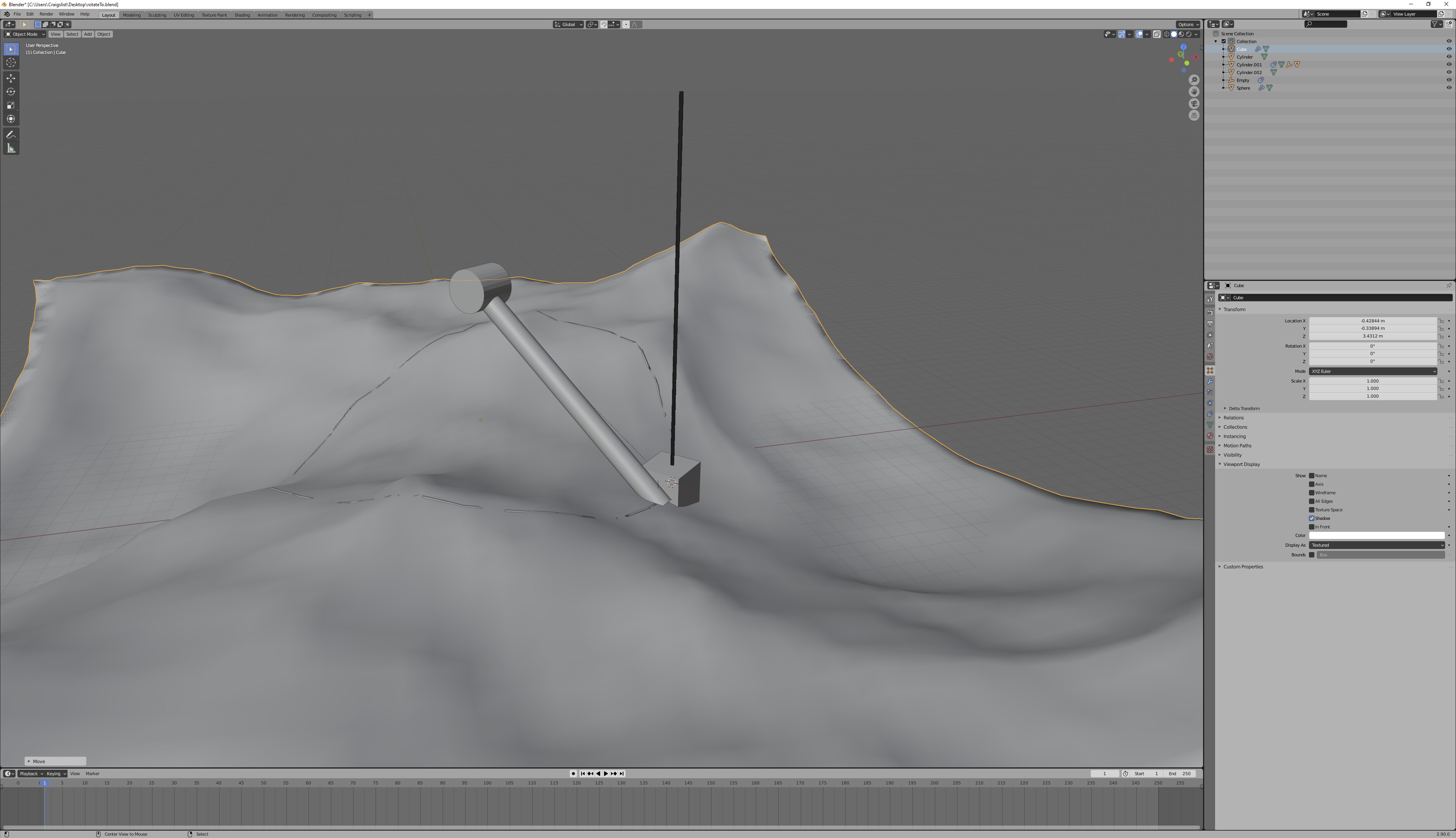
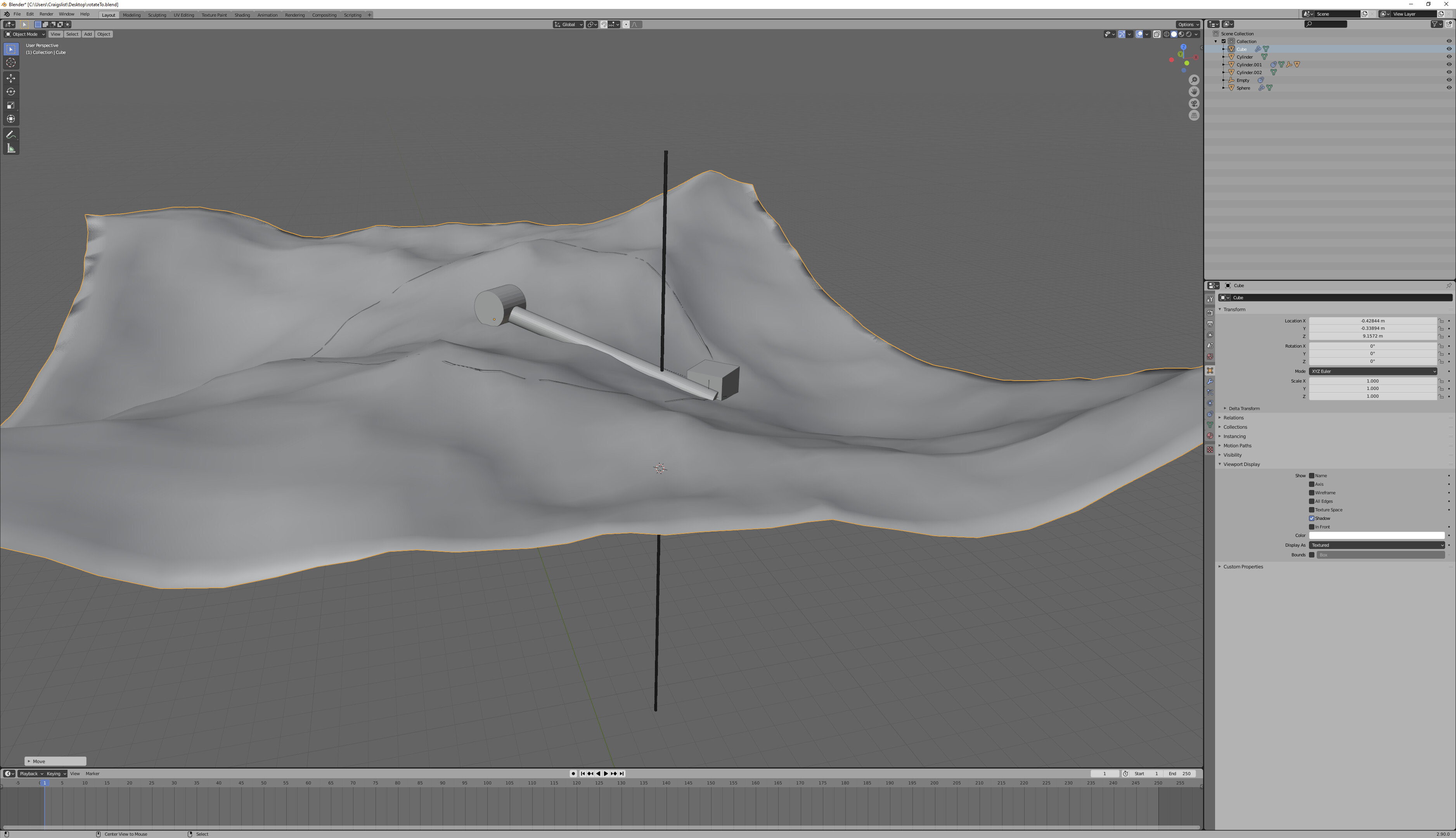
Well I have been doing it for days. Apparently in Blender I can make something attached to an arm be affected by the ocean and translate that to the rotation axis of the arm. The arm does not stretch …it just rotates when waves affects the position of the cube
Notice the length of the arm (the same). Notice the position of the cube relative to the wireframe cylinder marking motion that would occur only in the world Z axis.
Let’s look at what happens when instead, I lock the XY position of the cube:
Maybe I am explaining wrong. Here you can see what I am trying to achieve.
I am using two empties:
One empty is shrink-wrapped to the ocean and the other is fixed to a position.
The rotation of the cylinder is being driven by the distance between the two empties.
I think that it’s not remaining fixed, or that the cube is moving in more than the Z axis, but that you can’t see it because you’re using subtle ocean movement, so your error is also subtle. If you increase the size of the waves, or raise/lower the ocean, you’ll see that it doesn’t work right.
I mean, it’s okay if stuff doesn’t work right, as long as it’s good enough. But if this is good enough for you, I don’t know what you’re asking.
I think now I got what you meant. I understand. Yes indeed a rotational arm will always move the tip in more than z location…if not you can not describe a circle.
I got it. Its more about what you said. In this context the cube moving in other axis is not relevant.
It is relevant, because it will change where, on the surface of the ocean, it needs to float. Look at some more extreme situations with what you have and you’ll see the problems.
I think it’s a problem with how I communicated my problem. This morning, a bit fresher can explain better.
I think we got stuck in the conceptual problem and technicalities.
Anything attached to an arm that rotates in a perpendicular axis will move the buoy in a circular way. The buoy will move within a plan XY or whatever plane where the axis Is placed perpendicularly. So yes, the buoy will move in within a range of coordinates in two axes. I agree and you are right.
My mistake was in the phrasing of my issue. What I need is to input the z value of my buoy (I can not find the other movement) and translate it, if possible, to the rotational axis in degrees…I know that the axis should have the values also of the other coordinates, but I will need to fake that. I need to use Z axis values of the buoy and find the equivalent in degrees to input to the rotational axis.
MMM not sure if now is better hahah
I think I am closer now with the drivers method. Are you familiarized with it? I am going to open a new topic. The title of this one does not correspond to the new method I am trying.