Voronoi Cells gradient or pattern

Can’t figure this one out.

I want to take the voronoi cells procedural - and have either a randomly rotated gradient or a random pattern within each cell.

It’s easy to overlay a pattern over the voronoi cells - however this pattern is continuous between cells. I would like my pattern/gradient to be discontinuous.

Can this be done?

Sometimes you can feed one texture into the vector input of another texture to distort it. Maybe its possible with voronoi?

Perhaps something like this?


Using a similar approach as my world2tangent setup,:


this is suppose to work with 2d textures, but using the cell.value as the Z coordinate can easily be used in procedurals. The object should be unwrapped, for the tangent vector (using the generated tangent will rotate the resulting vector around the Z axis of the object).

3 Likes

Thanks - i’ll take a look.

Oooh nice solution!

Worked great - thanks.

Only problem is (and I don’t know if its because of the complexity of the node setup) - but it doesn’t seem to work with microdisplacement.

I had intended to feed the result of this into the gradient texture and drive the microdisplacement in Blender 2.8RC2. Although the node setup does create the correct result when plugged into the colour slot of say a diffuse shader - when I feed the result into the displacement slot - it does nothing.

It’s strange - I would have expected the displacement to simply take the greyscale texture and apply the displacement - but it doesn’t work, even when run through a math node to multiply it.

This is something I had noticed before. It’s quite odd because it seems to be outputting a numerical range but I also couldn’t get that output to act as a displacement whatever I did to it with ramps, maths nodes etc. yet you can do the same with a noise and it displaces fine.

You might have to scale the output before using it as displacement. I’ve tried manual linstep/smoothstep (math nodes) with success, but not a color ramp yet.

I’ve cross with similar situations before (at least by using the bump node to find derivatives to use them later). It turns out that there’s some limitations on how the SVM deal with this kind of logic, and the only way to pass over it is to bake, or do it through OSL (in the particular case from this thread, OSL is the best option) .

What does SVM mean? Any more info on this limitation?

Anyhow, I tested this and I have to concur with 3pointEdit - nice solution. Although I didn’t quite figure out what the original problem was :slight_smile: It’s nice and brilliant, but I can’t wrap my head around what is actually going on. I’ve setup a completely different way, if the idea was to scramble the UVs up based on colored output from voronoi. I’m getting 6 “different” (enough, 3 last ones is just a hsv modifier using the same color output) outputs plugged into a custom mapping node, since the vanilla mapping node doesn’t allow anything to be plugged in. See Bartek Skorupas tutorial on how to setup your own (nice utility and I use it or parts of it constantly).

You may not need all of it, or need to scale the used values differently depending on your needs, but the flow of it should be easy enough to follow:


You can also take the fac output of the voronoi and separate effects using a series of greater than and less than nodes and just add up the effects in the end.

SVM states for ‘Shader Virtual Machine’, and it’s the part of Cycles that deals with shaders.

The limitation in just because when we use the bump node, Cycles (or the svm), probes the texture at least two more times to get the derivatives at the coordinate being sampled. What I suspect it does, is that it changes P a bit and sample the texture again… (at least I know that if you have an OSL texture and want to use it with a bump node, you need to use P from the geometry node and not P accessible from the OSL::Globals). This limits things a bit when we want to hack the bump node to produce other things than normal vectors. (like producing coordinates from the normal, as in the node setup I posted).

What’s going on is just a projection of the bumped normal vector into the tangent plane of the surface, and use the coordinate of that projection as a UV map. We can imagine the bumped normal is a unit vector placed on the surface, with it’s own inclination; if we Dot(Normal, Tangent) we get the cosine of the angle between the normal and the tangent vector; and we do the same to the cotangent, but because we don’t have a cotangent, we need to build one with Cross(Original Normal, Tangent) which returns a new vector perpendicular to both input vectors. We can use these cosines as U and V and use them as coordinates for other textures. I added 0.5 to them just to keep the origin of the coordinates in a corner, otherwise it would stay in the center of each voronoi cell)

1 Like

Ok, thanks for the explanation. Man I wish I could stay awake during math class back in the day :slight_smile:

I have been trying to make a procedural crystalline texture as a personal project to learn procedural materials but I can’t quite get it to work. My aim is to have a voronoi pattern that has a gradient across each cell with each cell’s gradient being at a different angle, thus creating a bump map of crystalline-like surface with each cell oriented at a different angle in a unique direction.

I found this thread that has helped me get most of the way but the result I am getting is not quite what I was hoping for and its more than likely due to me not fully understanding things yet.

When I apply a gradient texture to the output vector it doesn’t give a linear gradient but rather a radial one around the centre point of the voronoi cell. What should I do to turn the gradient to being linear?

  1. create a local coordinate system tangential to the surface by using the tangent and the cross product between tangent and normal. Compute the x and y coordinates by dot-multiplying the difference between the position on the mesh and the cell center with the tangent and the cross product. set the z coordinate to zero

  2. use the mapping node to rotate the local coordinates. compute the angle from the cell color (so it is different for every cell)

voronoi_gradient_4.0.0_v01.blend (986.8 KB)

EDIT: but if you are only interested in manipulating the normals, you can do this directly:
voronoi_normals_4.0.0_v01.blend (967.2 KB)

EDIT 2: What you can see is that the individual facets do not appear flat but follow the curvature of the underlying mesh. If you want them to be flat, I think you have to bake a normal map first, see

5 Likes

Wow this was a really useful lesson! And I took the time to understand it and since I haven’t seen too many clear explanations of these nodes I thought I would share my understanding of how this works.

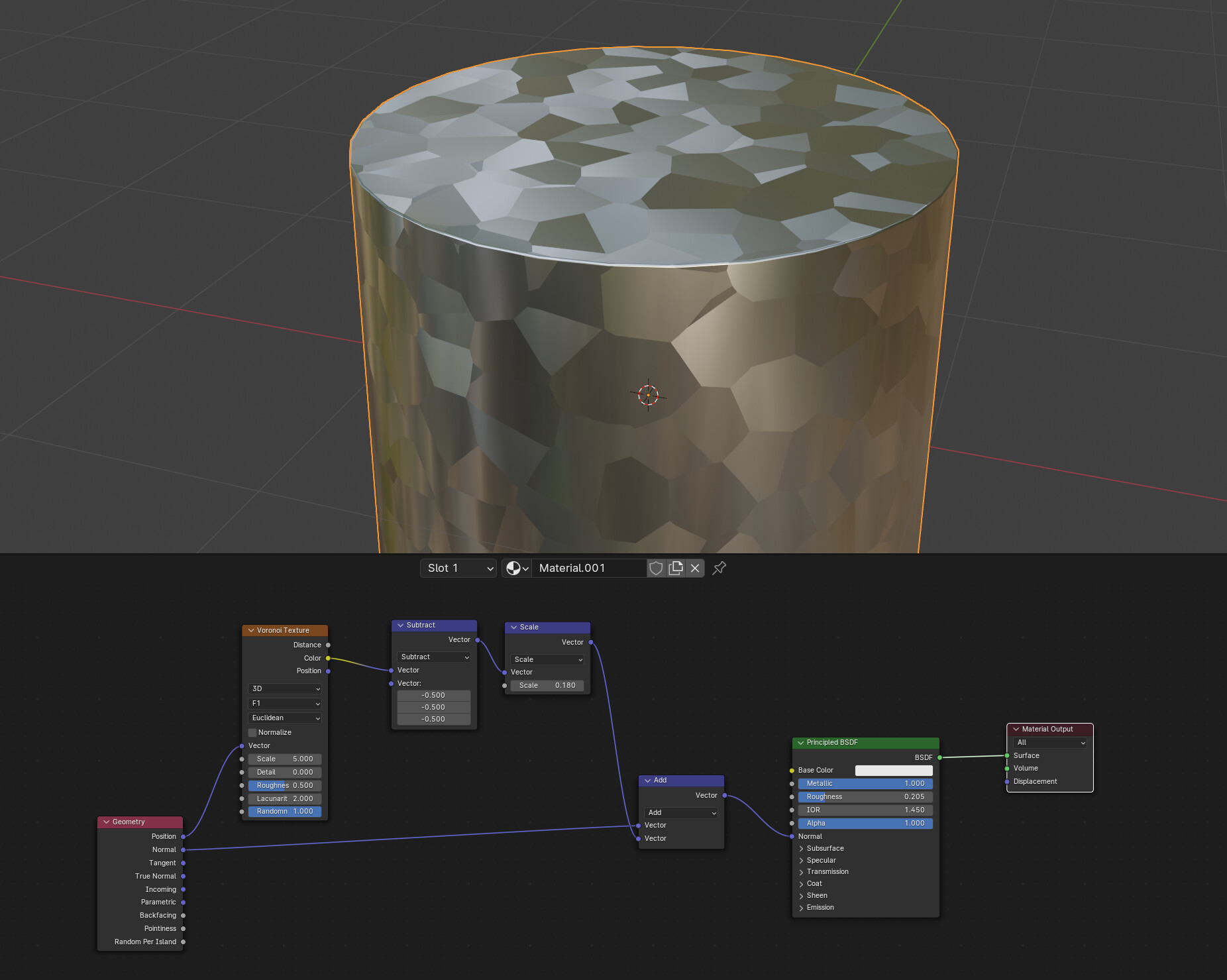
Although quick side note I realised thanks to going through the understanding of the vector maths that using the geometry position vector would affect both the voronoi cells and orientations if I moved the object due to it being linked to the world coordinates. Using the Object Texture Coordinates instead fixes these values to the object itself:

So I hope this explanation helps anyone like me trying to learn procedural methods as well as just revising their vector maths.

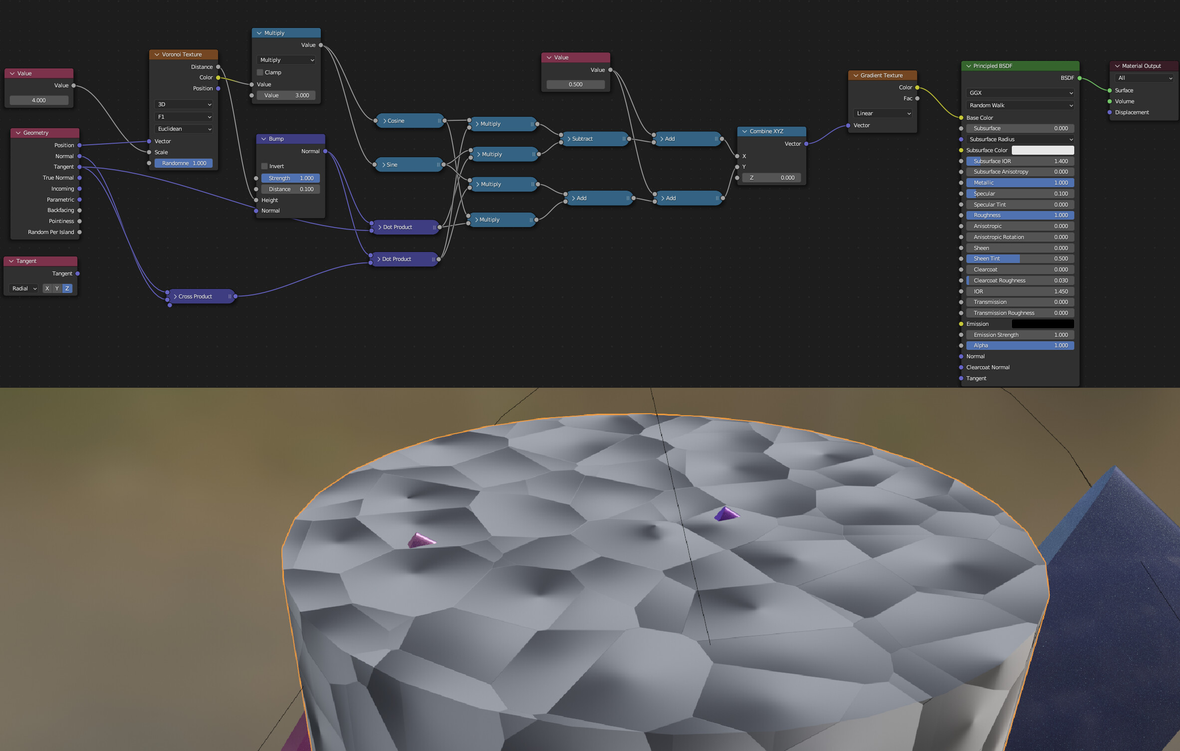
Using the object coordinates to drive the voronoi cells means that the cells all take on the same vector equal to the one at the centre of the each voronoi cells.

Subtracting the voronoi position vector from the object vector causes each cell to produce vectors that are inward facing towards the centre of each cell.

Taking those resulting vectors and performing a dot product with the geometry tangent vector causes the result to be essentiually a measure of alignment of the inward facing vectors with the tangent vector, thus producing a gradient in the tangent direction of each cell.

Doing the cross product of the normal and tangent geometry vectors creates a bi-tangent vector across each surface which is another tangent vector that is perpendicular to both the tangent and normal vector (hence its name of bi-tangent).

Performing the dot product of this vector with the subtracted voronoi and geometry vector (which produces the field of inward facing vectors towards the centre of the voronoi cell) creates another scalar gradient which is actually perpendicular to the previously created one.

Combining these two as X and Y components with Z=0 creates a field of 2D vectors with X Y values along each voronoi cell. These vectors contain gradient information in both the X and Y directions, essentially capturing how aligned the inward-facing vectors are with both the Tangent and the Bitangent (or the secondary Tangent perpendicular to the first).

Then we use a single RGB channel from the voronoi colour cells to drive a random rotational value in the Z direction through the mapping node to rotate the resulting gradients in random directions.

It was so useful to run through a working example.

To @LordoftheFleas, What I am trying to do in the end is also add in the ability to vary the intensity of the gradient (so affect the contrast of the bump per cell), as well as the average height of each cell (so brightness) so that the texture can affect the direction of the crystals, slant, and height. So that is what I will work on next. Thank you for the help.
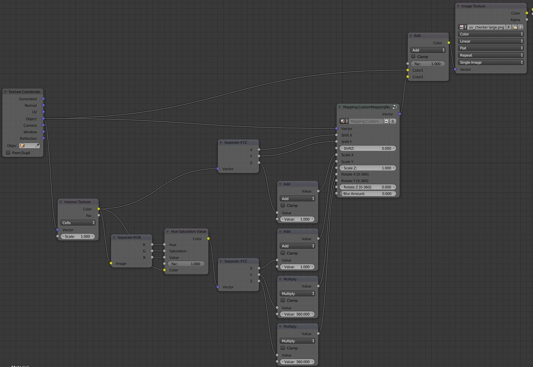
3 Likes