yes, but cycles is not spectral, so no dispersion effects would show even with 10 billion samples.
Just be careful with the quantum computing magic bullet nonsense. By the time that technology is mature enough to be usable, cycles will be hopelessly out of date, and you will need a new renderer anyway. Let’s not sacrifice usability of current technology for the faulty idea of future-proofing.
I do agree that we shouldn’t rely on hypothetical future technology as a driver for development, but there has been a few papers on importance sampling techniques (for spectral effects) that can be applied today (if Cycles had the ability to do the calculations).
One recent paper for instance showed a dramatic increase in the convergence rate for things like chromatic dispersion, such techniques should be applied as part of an initial implementation of such shading.
Shifting everything over to full spectral calculations would be quite the undertaking. It’s not just the renderer, all the materials need to take complex IORs into account.
Spectral rendering, much like caustics, is a special effect which is rarely needed, and if needed, is often easily faked. Cycles is intended to be a fast, semi-realistic animation rendering engine. Bolting on more and more features to make it more realistic will take away speed, and lose focus on the intent of the engine.
If you want a super realistic, spectral rendering engine with caustics and bi-directional support, use mitsuba. Or yafaray. Or luxrender. or any other rendering engine that is built with that end in mind. Trying to make cycles into something it isn’t doesn’t really help anyone.
I don’t understand why the talk about spectral rendering continues when it’s certainly not necessary in order to have dispersion. Even dispersion of such quality required for high end jewelry visualization doesn’t need a renderer to be spectral.
With that being said, Cycles is still a bit lacking renderer, and it lacks in this particular area as well. The theory of dispersion in non-spectral renderers is simple: You add red, green and blue refraction with slight IOR offsets, and you get dispersion. In case of cycles, you need to add negligible amount of roughness to trigger ray splitting/branching:
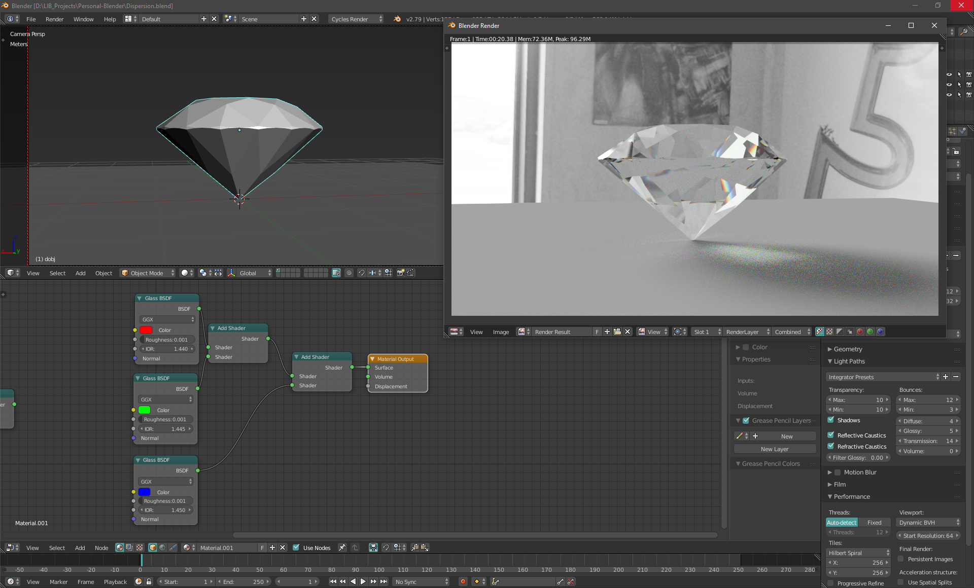
However, there are several issues with this:
1, Glass BSDF roughness affects not only refraction, but also glass reflection, and in case of glass materials, you need to have reflection perflectly sharp
2, Glass BSDF has a reflection layer, and you do not want to add 3 layers of reflection, as you don’t want to break energy conservation.
That’s when you actually realize that Cycles’ glass implementation is completely fubar, when glass color actually tints the reflection color as well… WTF? Glass is not a metal, it’s a dielectric 
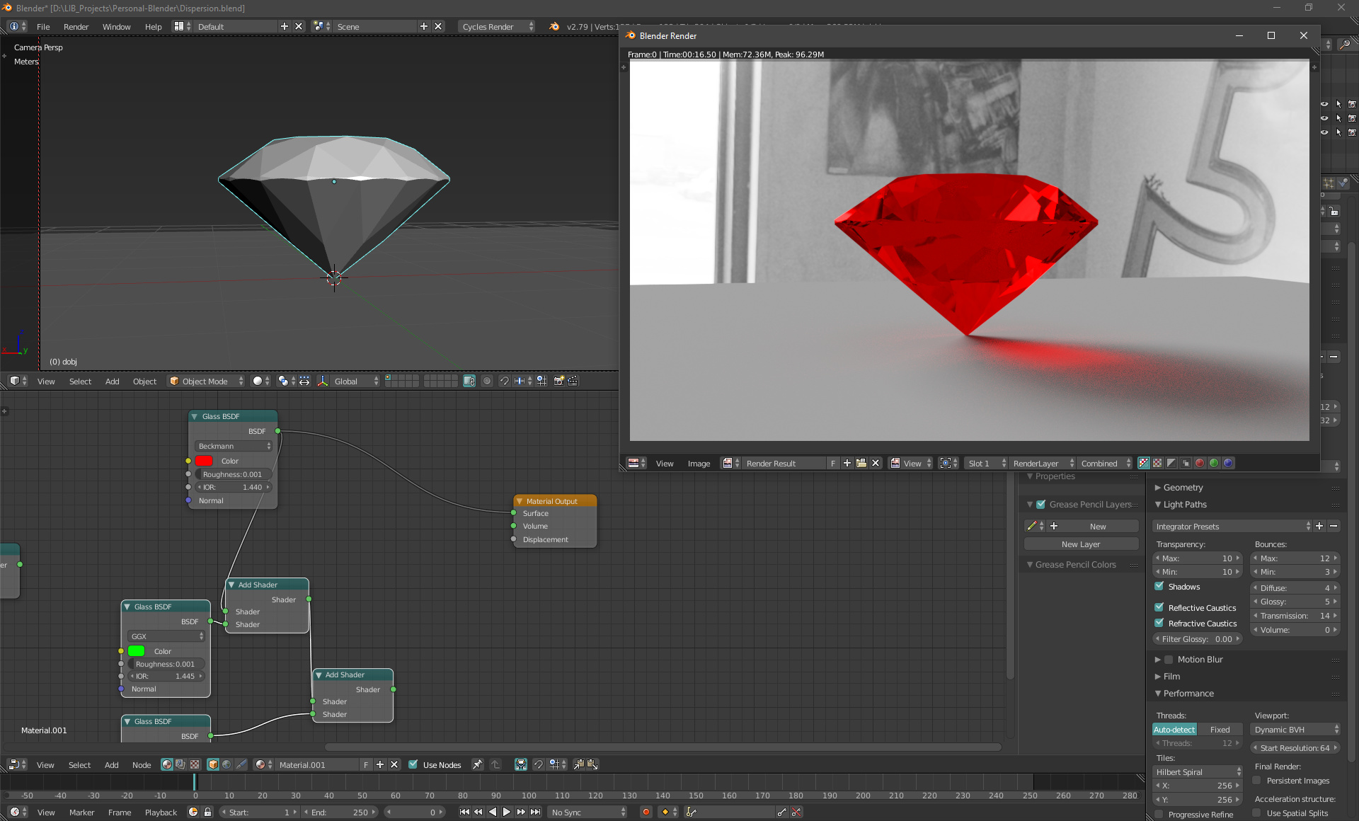
So actually, thanks to a bug in implementation of Cycles’ glass BSDF (I am really surprised no one has spotted something so serious), the second problem of three glass reflection layers being added is absent. That doesn’t change anything on the fact this should be fixed.
With that being said, the first issue is still there. The slight refraction roughness blurs our reflection as well. The proper way to create dispersion would be to add 3 Refraction BSDFs, and then mix one Glossy reflection layer on top masked by fresnel, but that’s when yet another bug comes into play. If I add 3 refraction BSDFs, I get large black areas, which is all the more odd considering Glass BSDF, which is basically just a compound of multiple BSDFs works properly:
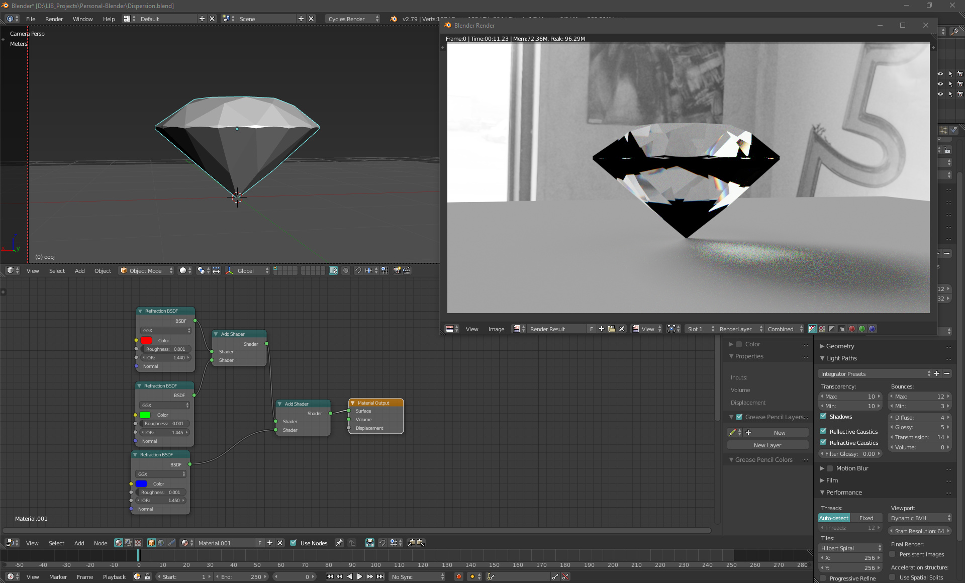
So, if you are willing to compromise some quality, and have your dispersed glass looking a bit dusty/smudgy, the first solution will work for as long as the glass BSDF reflection tint bug is not fixed (Which it absolutely should be). Otherwise, if the refraction BSDF add bug gets fixed, you should be able to get the correct dispersion. After that, hooking up a few more nodes to derive IOR value offsets for different color channels from user input Abbe number should be trivial.
It would still of course be ideal, if this would be added internally into Principled BSDF node
Well i still think Cycles will undergo major changes in 5 years do to massive advances in computer performance, and i do believe even universal quantum computers are coming along way way way sooner than originally expected, thats after the latest comments from experts i read about intel’s 49 qubit quantum chip. if you’d have asked me a year or so ago i was under the impression that a universal quantum computer was at least a century away.
You can get colored glass with a white reflection by using two colors using the fresnal node as the blending factor.
Also, a more realistic colored glass would use a absorption volume shader (making for a deeper coloring in thicker parts).
For heavy customization though, you can make a glass shader via the refraction shader, and transparent shader, and the glossy shader (but you won’t be able to use the great multiscatter GGX model for rough glass). As for the black areas forming, many people have done the three-shader addition to great effect in the past, so it must be a bug.
Getting colored glass with white reflection by using fresnel node would be a quite inaccurate workaround for the bug that should be reported and fixed. It’s really a fundamental problem. Only materials with colored reflections are metals, and at the same time, there are no transparent/translucent metals.
People like me and you know that of course, but we should also think about new users, people who are just getting into realm of rendering, and have tools that naturally lead them to good looking correct results.
HolyfuK:p¬ even volume roughness:yes:… and that’s how it is, running in cycles :spin: but thankfully are here & there & everywhere many helping each other… get out of darkness! - Simply imagine… & puf-pufff… twitty-tweet… there’s a solution 
with 2.8 on horizon, every support is quite welcomed… @ least better then ayayay…
in short be or don’t - a problem or a solution
& have a great Old New Year 2018 
simply amazing, enjoy all
Well, it could be due to no one bugging Brecht over the ‘fundamental flaws’ of the glass node over the years (it has worked like that ever since the engine’s initial debut). The majority of people preferred the method of improving the glass shader using other nodes and bundling them into a group.
Though maybe the devs. will get more inquiries about making sure Cycles gets shading functions correct now, considering that Cycles is getting features that is starting to attract more professional users and how 2.8 is said to be a release that can break tutorials, workflows, and existing scenes.
That the advantage of the procedural method I posted earlier - you can use 100% sharp glass shader.
If you absolutely refuse to use Moony’s pefect solution to the problem… Well, you can do it with Refraction BSDFs as well, there is a problem with ior values for backfaces, you can find some info here. While it is a problem and the bugs should be fixed, you do not have to compromise any quality - solutions exist. Just ask for help in the forums and you are good to go. ![]() Unless of course you prefer it not working. Then, yes, you are right. Cycles is not a capable render. Those darn hobyists and their non-industry-standard software… Hgrrrrr…
Unless of course you prefer it not working. Then, yes, you are right. Cycles is not a capable render. Those darn hobyists and their non-industry-standard software… Hgrrrrr… ![]()
Are you serious?
Moony’s solution is just semi-random tinting of refraction channel based on the brick texture…?! It’s far away from the actual way dispersion behaves. And the link you shared, that concerns completely different problem - simulation of a thin walled refractive material. I don’t even know what to say.
There’s also texture-based changing of the IOR value, so a ray hitting a red micro-brick will bend less than a ray hitting a blue one.
I do agree that there should be the option to have more physically correct shading out of the box, but we need to realize that Cycles is also about artistic flexibility (hence why many shader nodes shouldn’t be used by themselves). There is also the idea that one should just enjoy the process of making art rather than worrying about correctness to the tiniest of details (because in many cases, the difference between a scene with ‘correct’ shading and a scene with less correct shading, but pleasing to the eye is barely noticeable).
In short, there will be many cases with slightly inaccurate shading (just a few percentage points worth of error) being missed by people looking at it unless they have a degree in material science or they closely scan every individual pixel.
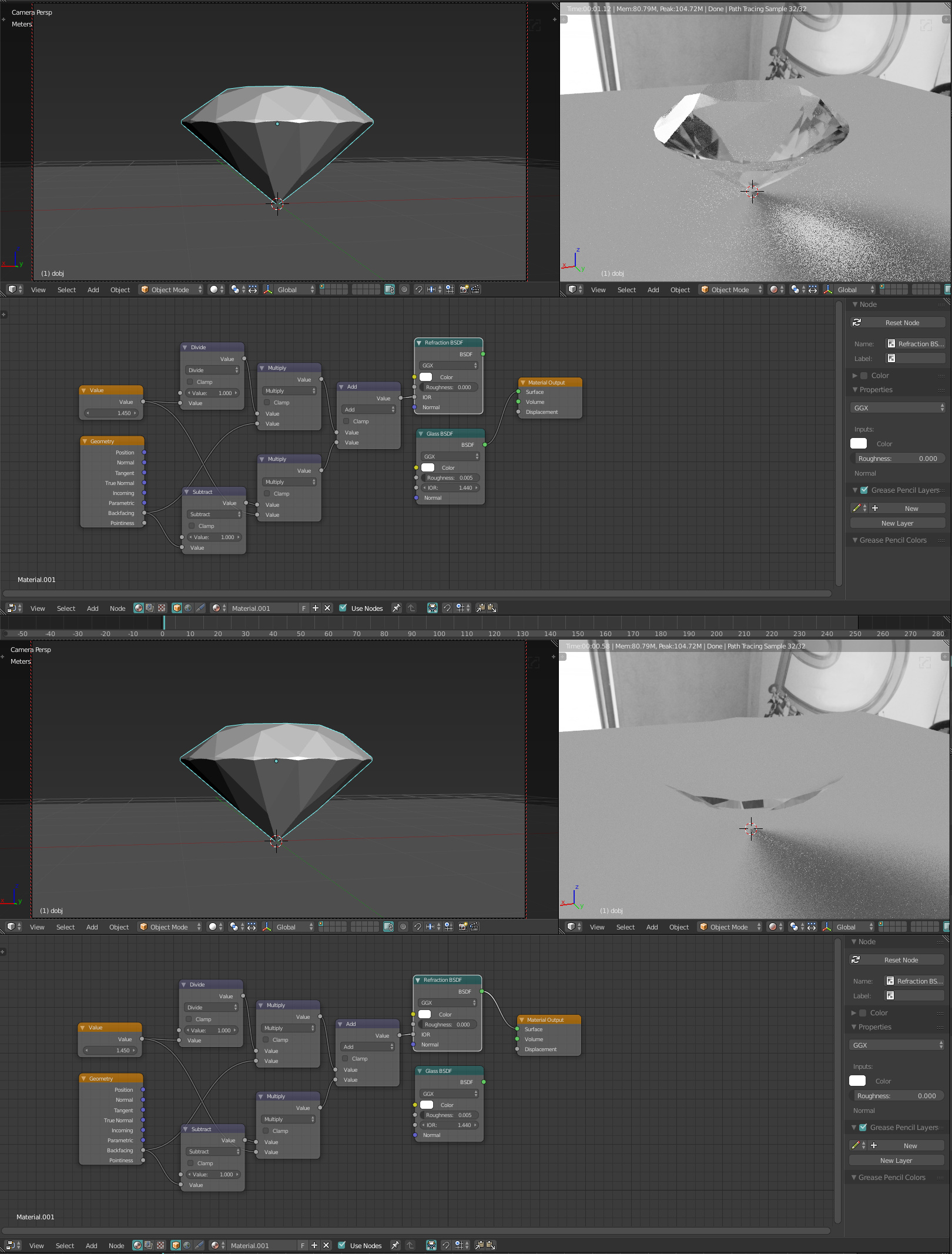
OK I’ll be honest with you, I am not directing my full attention to this - I might be mistaken, however: 
Provided I did not misunderstand anything that I skipped through, it should not be too hard to go from there. Fresnel node also uses IOR, so it needs to be plugged in there as well, or you could avoid it altogether and have custom Fresnel’s curve like this:
It sometimes feels as if you really love complaining about how bad Blender is. Sometimes it feels to me as if it was a bit too much. Sorry if I am wrong.
Oh and by the way, I have no idea, how Moony’s solution works, I just trust the guy. If he says so, I just think there must be a reason. Moony, what kind of magic is that, seriously? ![]()
![]()
![]() Why does it work? Do I understand it correctly? You have a texture that when a single pixel is sampled randomly it happens to match a smaller point on the proceedural texture and then if it happens to be one sort of IOR from the texture, then it must also be the specific color driven by the same texture, so it’s the same as if samples are taken with specific different IOR values that match the specific color for that IOR? WTF, man?
Why does it work? Do I understand it correctly? You have a texture that when a single pixel is sampled randomly it happens to match a smaller point on the proceedural texture and then if it happens to be one sort of IOR from the texture, then it must also be the specific color driven by the same texture, so it’s the same as if samples are taken with specific different IOR values that match the specific color for that IOR? WTF, man? ![]() How do you even come up with stuff like that?
How do you even come up with stuff like that? ![]() I am seriously impressed.
I am seriously impressed. ![]()
I am even more confused now as I don’t see how what you are showing in the gif above is in any way related to dispersion. If it’s just a fix of the black areas problem I described, then fine, but:
1, End user should not be expect to plug a math equation into IOR slot of refraction node in order to have it working correctly.
2, It’s actually not working correctly. There’s an extreme difference between that arbitrary math plugged into IOR slot and actual real refraction. I actually appears to be doing 2 refractive medium entrances instead one entrance and one exit:
3, The second picture I understand even less. I can easily mix refraction BSDF with Glossy BSDF using a fresnel curve, I never said otherwise. I just can not mix three Refraction BSDFs due to the black areas bug, which your workaround doesn’t really solve without severe compromise in accuracy and quality of the refraction. Maybe I missed something, but if you know how to go from there to an accurate dispersion effect, then I would love to know.
And yes, I do complain a lot indeed, and I do realize it. I’d argue I complain about the ways things are done in Blender about as much as you defend them ![]() But I think it’s more beneficial for development progress to point out weak spots so they can be refined. “Things are great just the way they are” mantra never helped to improve anything.
But I think it’s more beneficial for development progress to point out weak spots so they can be refined. “Things are great just the way they are” mantra never helped to improve anything.
It’s actually not all that different when you think about it.
Because the tiling of the procedural texture is so small (sub pixel) - you are in essence calculating multiple IORs and multiple colour channels per pixel - just as you would for true dispersion.
I can not agree with an implication that physical correctness in any way interferes with artistic flexibility. You can see the proof all around you, for example:
- V-Ray being the most used renderer even for heavily stylized projects
- Disney, a company based on artistic expression of characters, objects and environment has been pioneering and pushing hard physicall based workflows
- Games, which arguably require even higher degree of artistic control than offline renderers have been adopting physically based workflows heavily in recent years
On the other hand, I do agree that small differences in quality do not justify significant increase in renderer complexity and speed. However, that is not the case here. The fixes to the bugs I pointed out above would in no way make Cycles more complex or slower renderer. And the reason I said the brick texture workaround is not sufficient is following:
While it will definitely give you something that an average person would perceive as a dispersion, imagine if you were an artist who specialized in the jewelry visualization, and you would decide to make a switch to blender. Blender is actually a great choice for this, because jewelry design is not the kind of work that requires some complex scene assembly, and also the way Cycles rendering is integrated and interactive with blender is a huge selling point for this kind of look development work.
But your clients are people who look at diamonds up close all day, they are used to seeing the nice spectral rainbows when looking at a gemstones, so if you send them a Cycles output with fake brick map driving the dispersion effect, they will probably immediately pick up on all the odd tones and angles going on in the gemstones, and return the image saying it just doesn’t look right. Yes, it will be fine for average blender user who does it for a hobby, but look at it this way - If this average blender user had actual real dispersion feature at his disposal, which is driven with just a single parameter (Abbe number), this user would then be able to render a lot more convincing gemstone, with a lot less setup. It would be just tweak of a single slider instead of cascade of 6 nodes with one minute of setup spent on each of them.
I can’t see how this would be a loss for anyone ![]()
Actually yes, I probably have not spent enough time looking at your image. I apologize. You are absolutely right, it’s the solution I would have never thought of. I am just having a hard time figuring out how would I go about more precise mapping of specific IOR values to specific colors, because it seems that colors inputted in the ramp that drives IOR are passed in RGB values. How does that translate into specific IOR?
Essentially what you have is a random pattern of squares output by the brick texture. These squares are different shades of grey from pure black to pure white (0-1).
I then map these greyscale values via math nodes into to a colour ramp which changes the grey into the RGB value corresponding to the wavelength of light. So what you end up with is a random patchwork of colours.
By mapping the same greyscale values through different math nodes - you can also convert the greyscale values into IOR values.
Put these both together into a glass shader and what you have is a checkeboard pattern - where each colour has it’s own corresponding index of refraction.
You then simply reduce the texture down so that it is sub pixel in size. This means that each pixel in your scene is sampled by multiple squares on the checkerboard and as such, each pixel ends up as an average of all the colours and IORs that make up the checkerboard in that pixel.
Since the contribution of each checkerboard square depends on the color and the index of refraction - it changes depending on the viewing angle, internal reflections etc - so you’ll get different distribution of colour contributions for each pixel depending on how bright or dark the sub pixel checkerboard is for each colour in the pixel.
Think of it a bit like pixels on your computer monitor. Each pixel is made up of an R, G and B subpixel. It’s the same thing here - except I have many more sub pixels of many more colours (if the texture was small enough - each pixel could in theory sample 256 colours and IORs)
1 Like