A Script to Import a CSV File and Create IPO Curves/Meshes (for Blender 2.4x)

Hello everyone,
This is interesting, Hans! Flat files into 3D, lol. Clever work, and highly useful. Thanks for showing.

For the post regarding the river bank data: are you hoping to view the resulting vertice cloud as a final representation of the data? Or, are you looking to put a mesh together?

I’m working in a .blend file with 66,665 vertices from a 360-degree scan. I am having a very hard time creating faces by using point to point selection or ALT+B marquee select. Not only is it numbing and slow, but I can’t easily read the topo, not in orthographic views nor in trackball mode. All verts are the same color, all represented on the view-plane-- easy to join verts into faces that cut through rather than over the object.

I was hopeful that Hans’ work could be a base of inspiration to deal with the results of importing point cloud data. There is a company, SyCode, that has successfully “skinned” clouds of terrain data. It is hundreds of US$ to purchase the solution, but hopeful for Blender that they used a draped plane to achieve it. Blender has such a drape, in theory. I haven’t found a way to “freeze” it once it rests on its target…

I need to assign faces to my cloud. I found this thread after trying to create a binary file of the .blend, in hopes of converting the file to .sfl format, which is specified by the makers of Pointshop3D. My attempt at converting .blend > .vrml > ASCII failed to be recognized by Pointshop3D… I’m sifting for ideas but I’m an art director, not a programmer. If this problem interests anyone, here is what I found:

http://www.sycode.com/products/point_cloud_ac/index.htm

http://graphics.ethz.ch/pointshop3d/documentation.html

http://www.stanford.edu/~ctj/f2003/cs468/week1.html

  • opinions, conjecture and wild ideas are welcomed for where I should wander to find a solution. ;o)
[edit: duplicate deleted.]

D’oh!
I regret the double post-- my wordy response hung my machine, and I did not see my reply posted… so I tried again… first-timers…

Thank you for taking a time to tell us useful information, davinci990.
I wonder if what you said shows that there is already software which solves the problem of converting point data to a 3D mesh but which is not for free, in the world. I guess that it is not easy to make surfaces among vertices with connecting them if the vertices are located totally at random, because they have no information on what vertex to what vertex should be connected.
I just took a trial in Blender briefly. I made an Icosphere with pressing Space key and erased edges and faces with pressing X key. Then I got a mass of vertices which looks like a cloud as you said. I tried something like making edges again by hand to find out an algorithm for scripting, but it seemed to be too difficult for me because there could be so many ways of connecting even very neighbor vertices.
I just want to keep it up and your post let me know where the difficult point is. Thanks again.

Thanks for responding, Hans. Yes, I found the same as you. Here, heavily edited, is my post to a different forum, and it may be a way to get around:

"…I reasoned… a center plane intersection, segregating the outer verts into quadrants, is a useful way to measure their position in space from object center (0,0,0).

By (listing) trigonometric position(s), … a script could be used to always draw an edge along the bottom of any resulting triangle, using 0,0,0 as the peak.

…any set of adjacent triangles describing a 3-planed cone from the 0,0,0 peak would trigger a face being described at the base. …Beyond that, any butting triangles would be converted into quads."

Hans,
In better words, use the object bounding box to establish 0,0,0 reference planes that pass through the entire model at X, one at Y, one at Z or any box created by the user deciding with the existing ALT+B selector.

Then, begin finding acute triangles, all of them, and decide adjacency by comparing distance from 0,0,0. This way, even with toroids, you would be fairly accurate in describing outer walls from inner… even if results are large numbers of poles and n-gons to be re-topologized later. (Can’t v2.45 now do re-topo more easily than previous versions?)

The quadrant idea is to cut down on massive file size, (with seams stitched last, or by hand?)

Or,
you could step through the cloud like Stereo Lithography does-- a horizontal layer at a time-- drawing edges based on adjacency by distance/range from 0,0,0 reference based on selection by the user. The user would be advised not to select in-line verts (e.g., toroidal sections). This could be done by using the best view allowing selection of an uncomplicated section of cloud data.

By joining the slices edge by edge, they could be stitched into triangle faces from the level above, just edged. Ultimately the result, wherever the user stopped the process, could call the tri2quad conversion script already included in the application. Any n-gons or bad topo would need re-topo by hand.

Further, you could help the user “see” into the cloud by assigning each vert a color based on its distance from the view-plane. Borrowed from vert paint, this would show blue to be farthest away… up to red: closest. Could you then use a plane, parallel to the view, comparing the segments AV to VB?

|------------±----|
A V B

where:
A = stepping down (Z?) axis, computing verts on plane perpendicular to view-plane.

V = axis position of vert

B= bounds of model’s outermost vert (or selected portion)

There would obviously be need to re-topo the mesh, due to point cloud noise. And it would take some time, but surely this scripted attempt would be faster than point-to-point select by hand!

Where an inaccuracy would occur = |--------±-------±-----|
A v1 v2 B

(unless coordinates are compared from a table of coords?) In any case, automated basic skinning would be a huge help…

Hi Hans,
Thank you for your quick response and sorry! for my late response.
I send you a part of the points in CSV format (the original file is 45 MB) . I send you also a 3D image of the scanned points(area) to be able to imagine how it looks like.
Thank you very much for taking time to do what I have not yet been able to do.

Oh Sorry!, I though I could upload files, but I couldn’t. My email is [email protected], if you 'd like, you may send me your email address, so that I can send you the files, or if you know a way to upload a file in this forum please let me know.

best regrads

Hassan

Any way, here is a small part of my data:
3558425.449;5985726.14;13.04459095 3558425.421;5985725.898;12.68387413 3558424.99;5985727.52;13.16442108 3558424.753;5985728.276;12.67506313 3558425.889;5985720.218;12.57442093 3558426.051;5985719.739;12.84770203 3558424.415;5985729.576;12.81700039 3558425.253;5985727.431;12.79333687 3558425.051;5985727.141;13.13214207 3558425.89;5985724.183;13.12424564 3558425.847;5985724.064;12.80084801 3558425.797;5985723.799;12.64003468 3558424.049;5985730.104;12.64321423 3558425.105;5985727.137;12.68910885 3558424.957;5985727.052;12.60177135 3558425.641;5985724.831;13.16944981 3558425.936;5985724.197;13.03111458 3558426.007;5985724.226;12.8912468 3558426.474;5985722.27;13.00529194 3558425.716;5985719.254;13.09852123

Thanks for your replying.
@ davinci990: I’m thinking how I should implement the functionality (I became busy again because of starting the week, though.) The way that I’m planning to do for the implementation is similar to the second thing that you mentioned. But it’s in a more easier and specialized case. In point data, each point will have 3 components of x,y,z, and the users should set all of the x-coordinates at the same intervals, for example. Then the script will make n-polygons at each x-coordinate by connecting between the closest vertices which are searched around with measuring the distance. You will see the many polygons which are parallel to y-z plane, like a thinly sliced model. And next the script will bridge the polygons in the x-direction and skin faces by searching for the closer vertices in the same way. Such a way will not make everything be going fine but it’s simple and I think it’s good for the start line. Also I think it will work well for topology’s point data. (Sorry for my bad English if you can’t understand what I’m saying.)
@ topology: My email address is [email protected]. SaveFile file hosting service is also good to use for uploading files temporarily, which is found at http://www.savefile.com/. It allows you to upload files even without creating an account to sign in.
I feel like the data you provided at the bottom of your post has no regularity in the x-coordinates and it appears that it takes the values at random. If the points are located in such a random way, it would be a difficult problem as davinci990 teaches us.

Hi Davinci990,
Thanks for the useful information. Actually what I need as the desired end product is a 3D mesh out of a point cloud.
It stroke my mind right now, why not to use a 3D Delaunay triangulation method to create a 3D mesh out of 3d point cloud. I check it now if there is something in internet…

I have found right now some works regrading what I suggested:
http://vcg.isti.cnr.it/activities/geometryegraphics/dewall.html

http://www.ncgia.ucsb.edu/conf/SANTA_FE_CD-ROM/sf_papers/lattuada_roberto/paper.html

http://www.wias-berlin.de/publications/annual_reports/2002/node50.html

Yes, topology, I agree that triangulation keeps appearing as the best candidate. Thanks for your idea about Delaunay as an engine. I am not aware of this method; I go back to more study!

Can Delaunay be confined to an axis as it seeks combinations? As Hans’ test with the icosphere, there are MANY possible triangular positions. I think XY edges seeking triangulation with the XY slice “above” shows promise…

It would be convenient to have the entire cloud faced during a single operation, but not essential. I feel results could be enhanced by facing smaller sections–say, allowing the user to ALT+B select a small portion of the cloud to begin this algorithm using only active, selected verts as a cloud subset. Nevertheless, any holes or narrow crevices that were unavoidably filled might be corrected by hand.

Random considerations:
Topology, if Hans script failed to accurately describe the riverbank negative slope, could you accurately reconnect its faces? No verts would move location, but original profiles might be confused… so
Maybe the user should decide the “Z” axis? The viewer could recognize which slice axis would most preserve accuracy, and it would be easier for system RAM and screen redraw if the script could accept a variable for axis constraint, than to turn the model to fit the script. What is possible?

[badly worded comment deleted. My best wishes for your script, Hans]

Dear Hans, Thanks a lot for taking care about my problem. I have just send you a part of my point sample as CSV, with an image of the point cloud produced in the laser scanner software. You are right my point clouds are completely irregular. However, since the laser scanner emit laser ray as it turns about 140° around its base, the radial distance of the points with respect to laser scanner position is almost constant, every point is about 3 mm left or right of the neighbor point, also in vertical direction, It means it is already a gridded mesh, but I can not make any computation or analysis on it , unless a 3D surface has been made out of it.

Dear Davinci990, unfortunately, I am no graphic programmer and I don’t know also how Delaunay triangulation works, I have just used a software that applies this method to generate 2D meshes from topological data.
About post editing the triangulation faces,the problem is that, the surface which I would like to model is a very uneven surface, so I can not adjust the created mesh vertices afterwards (If I have understood you correctly).
I am going to test also 3D Delaunay to see if it works.
By the way, I tested the Point Cloud plug-in software for AutoCad, and it could not produce a correct mesh out of my data. I don’t know why, but I am waiting for the answer of the supporting group of the company.

Thanks, topology. I got the file and image. I will try to write a code briefly to import it into Blender and to make a vertices cloud tonight.

No need to delete your comment, davinci990. More comment will help me imagine what you’re considering.

lol-- Thanks, Hans. I try not to write comments that I regret later, but I have an imagination that isn’t always a help to more structured minds. Since I have difficulty with proper coding, I have a great respect for what your thought structure is able to accomplish. I was tired and frustrated from failed experiments, so my comment was less than helpful…

So, I turn my enthusiasm to rooting for your success. I believe 3D scanning is the future. As topology’s latest test shows, there is still considerable room for Open Source solutions to triangulating Point Cloud Data. This has been a stimulating run. Thanks for the discussion so far.

Now I finished making a vertex cloud from topology’s CSV data (but haven’t bridged any vertices yet.) Looking at the cloud that I got with easy coding for a short time, it looks more difficult than I expected. The riverbank negative slope is so bumpy as you said, topology. I guess it will confuse the script to decide what vertices should be connected, but I still keep it up.
I would like to ask you a question. Do you mind if I put a .blend file including your scanned data here in this thread to show the result and the script which I wrote for it.

Thanks, davinci990. I write codes a little but I’m clearly much more immature than those who work for the deveropment of Blender and its plug-ins. So the things that I can accomplish might be limited, but if someone makes a script to do that and shares it with everyone, it will be really great.

In order to show how to use this script more clearly, I just made video tutorials as follows. I have only the software that is translated into Japanese, so all the menu contents in the videos are seen in Japanese. However, I believe taking a look at the videos will make it easier to start to use it than only reading the tutorial at #1 post. Here are 4 videos and they are the main usage of the script that I expect.

+How to Use CSV Importer v0.5 beta2 Most Easily
+How to Import a Mesh with CSV Importer v0.5 beta2
+How to Import an Ipo Curve Automatically in AutoMode with CSV Importer v0.5 beta2
+How to Import a Mesh Automatically in AutoMode with CSV Importer v0.5 beta2

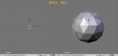
I still put my work for the point cloud this weekend. Topology’s data is tough so for now I started with a simpler point cloud, Icosphere cloud, which can be made by erasing edges and faces of a default Icosphere as I did in #23 post. And it was successfully turned into a skinned mesh which is the same as the original. I got a good result. Of course, it’s easy because all the distances between any two vertices in the cloud is about the same. So it could be done with an easy algorithm in which closer vertices were searched and sorted around each vertex appropriately to make faces. The following image is the point cloud and skinned 3D mesh.

http://bp0.blogger.com/_d4nbesSwQqc/R0AqSIy-ptI/AAAAAAAAAI8/uffIYXCeDDc/s400/PointCloudTo3DMesh_t7_20071118Pub_1.jpg

Here is the .blend file including the script code that skins faces.

All I can say is WOW. As an engineer way back when, this is FAN-FREAKIN-TASTIC Hans! YOU GET THE COOKIE today AND tomorrow. Thank you for this.

  1. Data points created by any simulation program, motion capture, or AI engine can be used to animate objects, including object motion OR bone motion.
  2. Data points created by any surface function program can be used to visualize the actual object.
  3. Data points sampled by any input device (2D or 3D) can be used to visualize the actual object surface, to include topographical surveys.

IMHO, this opens up a whole new world for Blender in Engineering departments.

Thanks a lot, PapaSmurf. Your comment is encouraging me. The third thing is still under development.
I haven’t ever seen people like you who gave such a summarized overview for data points. It shows exactly what the script can be used for and I can’t find any lack of explanation. It’s perfect, thanks.

Hi Hans,
Sorry for coming back with delay. Of course I don’t mind if you put my data in Blender forum.
I have just an idea and I don’t know if it works. but is it possible to make a search algorithm so that it selects a vertex and looks around it in a distance equal to a small sphere, find points around it and make triangular out of it. then select one of the triangular vertex and do almost the same to find some points around it and make a new triangular. The problem is then connecting the triangular together with new triangular. the algorithm seems to be not so easy!

The problem is then connecting the triangular together with new triangular. the algorithm seems to be not so easy!

I also guess it’s not easy. Connecting neighbor triangulars with no duplications and holes will be one of the most difficult problems as you mentioned. To make it possible, you will have to pay a lot of attention to where the points are located and what faces have already been made.
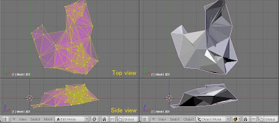
Last weekend I imported the point cloud from topology’s CSV data, and made it skinned using the simple algorithm I considered in #34 post. The way is almost similar to your idea, selecting a vertex, looking in a distance and making triangulars out of it, but it doesn’t consider the problem with connecting triangulars continuously. So you will see the bad result like the following image if you use the script based on the simple algorithm. It has a lot of duplicated faces and contains many surface holes.
The next thing that I have to consider is to find out how the duplications should be avoided and how the holes should be covered in. I have some idea for that, but the new week began again, so I’m going to do that this weekend.

http://bp1.blogger.com/_d4nbesSwQqc/R0MG4oy-puI/AAAAAAAAAJE/5GimmIDmEIQ/s400/PointCloudTo3DMesh_t5_20071120.jpg

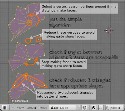
It is at night in Japan now and my weekend is going to end. I couldn’t complete a new script which I kept writing this weekend, because there were a lot of things that I had to consider when I wrote the script. What I have done is adding two new functionalities to the first simple algorithm. Now the script can check if angles between adjacent two vertices are acceptable. If the angle is too small, it will ignore the vertex. If the angle is too large, it will stop making a face. That will avoid making quite sharp faces which will make the final mesh look bad. Also the script can check if adjacent two triangles have appropriate shapes. It will reassemble the triangles into better shapes.

The following image is showing what I did for the script:
http://bp0.blogger.com/_d4nbesSwQqc/R0l6I4y-pvI/AAAAAAAAAJM/O7CRnu-Tnh8/s400/PointCloudTo3DMesh_t8_1_20071125.jpg

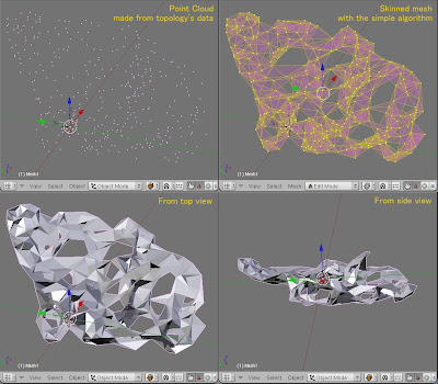
And when I finished implementing these two functionalities, I just realized that it was not so important. I applied it to topology’s data, but it still looks bad as follows because the script has no ability to conider what triangles should be connected. As you know, the most important thing is that I find out how to connect the neighbor triangles without overlapping them.

I applied it to topology’s data:
http://bp3.blogger.com/_d4nbesSwQqc/R0l6Joy-pwI/AAAAAAAAAJU/RdAsHGq_AjI/s400/PointCloudTo3DMesh_t8_2_20071125.jpg

However, I got another useful idea from thinking of the script and applying it to topology’s data. I know that the data is so bumpy that I can’t deal with itself using the algorithm that I’m thinking. So a different idea is needed for it. When looking at the point cloud, I felt like it looked as if it was including a lot of noise. And I wondered if some ordinary ways for noise reduction can be used also for the point cloud. The average of vertices in a larger distance around could be useful to know what direction the point cloud spreads toward. From such a direction you can caluculate an average normal vector around it. And what I’m thinking the next is to make faces based on the normal vector. I will transform the vertices and drop them on a plane which is orthogonal to the normal vector to treat them in a 2D way. Then I will make faces on that plane and transform them back again to restore to their original positions in 3D. This will allow the skinned faces to have a proper bumpy formation. Your criticism or comments are welcome (sorry for my bad English).

recusive programming programming approach might be good for this sort of AI thing you are trying to do. I would make Tris first, then when that is running move on to quads.

In other words, start with a face, any face. Then take the 3 outside verts in pairs (AB, AC, BC) and make faces from them as well by including one more vert as well (ABD, ADC, BCD). If the face made intersects with an existing face, try a different third vert.Repeat until all verts are part of a face.

OR, use the brute force method, and make faces from all possible combinations of three verts. Then go through each face, and if any of its edges intersects (passes through) another face, delete it. Something like that might work for constructing skinned meshes. Of course, if Solid display is on, you will only see the outside faces and all the interior faces will be hidden automatically (but your face count will be HUGE).

Either of these is very unintelligent. I like some previous’ suggestion to start with a seam, so you get a somewhat intelligent analysis/skinning of the object.

Another idea is to compute the center of mass of the verts. Then, start with a vert that is farthest from the center, and pick another and connect. I think the main issue with skinning is that a single solution will not work for all surfaces, and if you can skin an orange, or other relatively smooth surface, that would be a very very good thing.