A Script to Import a CSV File and Create IPO Curves/Meshes (for Blender 2.4x)

Hans, you are coming up against some of the considerations I tried to solve.

  1. Since I couldn’t assume any particular shape, I couldn’t assume any particular noise.
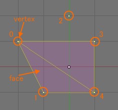
  2. This lead me to solve for triangles.
  3. Identifying triangles lead me to solve for edges, as I reasoned that faces could be asigned by CSV data on describing the edges, no?
  4. This identity problem lead me to naming all triangles in cloud with unique names.
  5. In several other forums, a brute-force algo has failed, so I assumed that finding intersecting faces would produce chaotic mesh.
  6. To reduce chaos, I considered divide and conquer by referencing = a single point established in the cloud to hold all triangles in relationship.
  7. I think that a way can be made to automate identifying by name the shared angles, so to group adjacent edges into triangles that can be faced.
  8. For simplicity, I assume a box model, where all faces are to the outside. This made indentations and crevices impossible, so
  9. I suspect all verts in a cloud must be further identified arbitrarily; I chose to use vertical layers. This would allow an orderly matrix, and therefore tables and CSV handling, no?

I apologize that I am at the limits of my abilities here. The point of my outline was to hyper-identify the point cloud, as brute force did not care about topo, but mass.

topology,
I think I have stumbled onto a Blender way to accurately depict the surface of your river bank data. Do you only require a surface representation, say, for a slide show image?

If so, I am awaiting permission to show the method on this forum.

I’m not sure I believe this statement. A single solution should work as long as the 3 closest points always form a surface. If this does not work, then the spatial sampling rate is too low, correct? In other words, a rough surface requires a higher sampling rate than a smooth surface. Skinning an orange (or a donut or a cactus) is easier the more points you have. The problem with the previous river bank data may be low sampling rate. If the sampling rate is too low, then it’s mathematically impossible to form the correct surfaces without additional data (e.g., normal vector, slope, etc.).

I hope this helps Hans, because this would be a great addition to Blender, for engineers and artists alike :slight_smile:

Thank you for so many replies and giving me so great ideas and your thinking. I was just a bit more busy at the beginning of this week, and now I could have a time to consider your suggestions, sorry for this late reply.

PapaSmurf’s second idea at #40 post is seemed to be very cool and I think it will promote to solve the problem with the trianglar connection which I just come up against. What I have learned from PapaSmurf’s idea is that it focuses its attention on the edge which hasn’t been connected to other triangles when you make surfaces, while I kept only looking at the vertex which I used as a center point to seach for the closer vertices around it and to make surfaces out of it. So your suggestion is very useful and it is definitely the one that I really want to know, thanks. I will try to think of it to write another script using your approach.

Honestly, I didn’t know the name, brute force method becuase I really have little knowledge about this field. It is however a way which I first came up with, but I gave up it soon because it could be easily imagined that so many ineffectual faces would be made, which would heavily waste memory and time to process.

I still don’t understand what is the advantage of the third idea at #40 post, but it uses the center of mass and that reminds me of something like a physics approach. Now I’m mainly thinking the way of looking at a vertex and aound it, but I also have another ideas for it. One of them is something like a physics approach which uses an energetic method and in which some particles are simulated in an appropriate field like gravity field, electric or magnetic fields etc. If you take a simulation by calculating numerically in such a field, it will give you an answer in which the particles have moved to their energetically lowest or most stable positions. And I’m hoping that it allows you to get correct positions of faces which skin the point cloud. But this method has a serious problem to overcome. I still can’t find out what kind of field models can make the particles move to the correct positions. I guess that the well known fields like gravity field etc will not calculate the answer for the skinning and it will not work well.

Maybe I think I understood the 1 to 5 steps of davinci990’s idea at #41 post, but I still can’t imagine what specifically it is like. Have you been researching the problem with point cloud for a long time? I feel like you have a lot of knowledge and hints on it, or even an answer for it.

grimey, thanks. It will really great if a way to skin any types of point cloud is found and a point cloud can be easily transformed into a 3D mesh. At least your mention is encouraging me. Of course, the higher sampling rate will reduce the difficulty of the skinning. If topology’s data has more vertices for example, just an easy algorithm might work well. However if the skinning technology is often needed for the point data measured by a laser scanning system or something like that like topology’s data, then the algorithm should have the ability to deal with it. I know the measurement always makes some of noise which is always bothering me. And a laser scanning system will be more expensive if you want to get the higher accuracy. So maybe more people will get happy even if the data has a bit low accuracy or low sampling rate.

At the end, let me show you a summary of the ways that I’m considering or that I got from your suggestions for the skinning.
+the way of looking at a vertex and aound it to make connected faces out of it (now mainly under development)
+the way of looking at a edge which hasn’t been connected to other faces (from PapaSmurf’s idea)
+the brute force method
+the energetic way of taking a simulation in an appropriate field (uncertain about the future)
+the way of taking averages of some vertices around and transforming the vertices into 2D (at #39 post)

Thanks again for lots of your help.

Hans,
I apologize for my deficient math skills. My Step 6 that you wonder about expresses verts in terms of trigonometry–

The idea is to generally assume that topology wants to be on the outside, for first pass simplicity.

Further, the idea is to divide the entire cloud into adjacent, irregular tetrahedrae, using a single location. In fact, all sides of the tetras are found using this single point. Thus, all topology made is formed opposite this peak common to all adjacent tetrahedrae.

You could make other possible tetras, so one way to assure adjacency is to assume working outside first then gradually back to the axis, and forbid faces drawn to a triangle containing (0,0,0).

So far, are trying to figure out all relationships in the adjacent verts without knowing any relationships to the whole.

I see no difference between a point cloud and a series of random coordinates on an XYZ number line construct. Is it not the fundamental of Trigonometry to describe any shape of triangle in any direction?

So, I ask a Python question: In what way can we describe the locations of a set of verts, even if they number in the millions? Once we do this, it occurs to me that we can more easily compare adjacency needed to draw tetras.

For example: [one vert, plus the center, plus another vert], would be named: {(1,1,0)(0,0,0)(2,1,0)}. It looks cumbersome but will be useful.

Located on our finite number lines as (x=1,y=1,z=0). This vert creates a “side” with our center, expressed as (x=0,y=0,z=0) Say the next available vert identified is found in space at (x=2,y=1,z=0)
Assuming that we forbid faces or edges that involve (0,0,0), we could assign an edge at {(1,1,0)(2,1,0)}

If we find the next vert at (3,1,0), we could automatically form angle {(2,1,0)(0,0,0)(3,1,0)}, and edge the side named {(2,1,0)(3,1,0)}

and so on…

Thank you for your explanation, davinci990. I’m a little familiar with trigonometry but not so much, and my ability of English is bad, so I’m sorry if I have a misunderstanding.

I’m wondering if you are showing the way to know what two vertices are the best to form an angle around a given vertex to make a face around it. I can’t express my thought with words, sorry. I hope the following image can give you what I’m considering.
http://bp0.blogger.com/_d4nbesSwQqc/R1QsGDqulqI/AAAAAAAAAJk/isuL3Kcgvng/s800/000052.jpg
A way to minimize the summation of the yellow colored angles in the image? As you can see in it, the two types of connection lead the different looks of the faces. The right pattern looks better than the left one.

I could have little time to spare a thought for your ideas even in the weekend, so I have nothing to show any results that you can see visually now. However, in order to decide what faces should be connected in the script, I created a new class called FacesManager to manage the existing faces last weekend. It can be used when you want to get the faces which a specified vertex makes around it. If you give a vertex, then the class will return the faces which is connected to that vertex.

I don’t know that Blender Python has such a functionarity already. If it has, I want to use it instead of my class, because it would have something like a bug which isn’t yet fixed and it has low performance. Please let me know if Blender Python has a functionarity to do that or something like that.

Now let me show you briefly how the class treats the data of the faces. I assume that you have a configuration of vertices and faces like the following image.
http://bp3.blogger.com/_d4nbesSwQqc/R1QsFzqulpI/AAAAAAAAAJc/5t4ml11b89Y/s800/000050.jpg
The vertices are named by the numbers 0 to 4 and it has two faces in it. And the data structure which the class has is as follows ([] means an array and it is the same symbol as Python language has):
Data = [ [[0,1,4],[0,3,4]], [[0,1,4]], [], [[0,3,4]], [[0,1,4],[0,3,4]] ]
When the structure has such a style, you can easily get the faces which a given vertex makes, for example, if vertex 0 is given, then you can easily get the set [[0,1,4],[0,3,4]] by calling Data[0]. The set represents two faces which are connected using vertices 0,1,4 and 0,3,4, and you can see the both faces have the vertex 0 that was just given.

Your comments, criticism, suggestions or anything will be greatly appreciated. Also it would be happy if you let me know another better way for that.

Good progress, Hans. I’ll look around for a similar Python class to the one you invented. But even with bugs, I like what you have been able to test so far with your FacesManager.

Must FacesManager depend on assigning an actual vertex as v0 for an array to gain a face?

In post #46, I agree your Pattern 2 looks better, but Pattern 1 is possible. Since the script cannot know which is which, I proposed that:

  1. An actual vertex may not be used as “center” or “v0” when it is possible to draw a face that includes that vertex.

  2. A temporary center, based on volume dimensions of the point cloud, or the subset selection of verts in the cloud, is one way to avoid using any vertex as “center”.

You are working on a different idea, so I’ll keep watching your progress!

Therefore, FacesManager would continue to assign a face = [0,3,2] ?

Hans, I see problems with your FacesManager. From your drawing, the faces you created [0,3,4] and [0,1,4] are not unique since [0,1,3] and [1,3,4] also define the same space. Since you don’t know which face set is correct, your algorithm could easily pick the wrong face set and, ultimately, run into problems.

You MUST have rule(s) for assigning faces…which is why I stated the 3 nearest points ALWAYS form a face. I believe this is the only approach that will ever work.

To calculate the distance to all points for every vertex will be very slow, so we must approach it intelligently. To speed things up, maybe try sorting the array of points based on their location in space. This will give you a 3D matrix. Your distance calculations only need to look in the vertex’s surrounding neighborhood of points (which is 26 points).

As your doing this, keep a running average for the distance between all the points you’ve assigned faces. With this average value, you can discard points that are in the neighborhood, but (probably) on a different face.

EDIT…

In fact, keep a running average and a standard deviation. If the distance falls within the average plus/minus a standard deviation…the vertex is part of a face. Otherwise, it can be discarded.

What do you think of this approach?

Thanks a lot for your replies, and sorry for my late reply. I would like to response your suggestions and comments step by step. So please wait for another minute.

Thanks, davinci990.

Must FacesManager depend on assigning an actual vertex as v0 for an array to gain a face?

Yes. You need to give an actual vertex to FacesManager.

Therefore, FacesManager would continue to assign a face = [0,3,2] ?

Yes. In that image, vertex 0 could be the center vertex to form faces around it, according to the algorithm which the previous script has. And it would continue to form other faces around vertex 1, 2, …4. As you know, it causes the problem with making too many faces.

I proposed that:

  1. An actual vertex may not be used as “center” or “v0” when it is possible to draw a face that includes that vertex.

  2. A temporary center, based on volume dimensions of the point cloud, or the subset selection of verts in the cloud, is one way to avoid using any vertex as “center”.

I’m not sure if this is the same as what you proposed but I would like to confirm whether I’m saying a proper thing or not. In your approach, you take a way of deciding somewhere as a center, but you don’t use an actual vertex as the center, because the center vertex shouldn’t have a face.
I would understand all that you kindly have been teaching me since #41 post if I learn the reason why the center vertex shouldn’t have a face. Like you mentioned, it makes a difference to use or not use a vertex as a center. I wonder if you don’t use a vertex as a center for some reason to avoid the intersection of faces. But even if the guess is correct, I still can’t imagine how it can avoid the intersection and what results from the difference is still not clear for me.

Thanks, grimey. I took a lack of my explanation on the purpose of the class. I’m thinking that I’m going to use it only to find what faces a given vertex has around itself, not to avoid overlapping faces, so it doesn’t have to understand the intersection like the sets of [0,3,4], [0,1,4] and [0,1,3], [1,3,4].
Instead, I’m planning to implement the functionality of avoiding intersection in another area of my new algorithm, so I have to keep working for that.

You MUST have rule(s) for assigning faces

Finally, what I’m planning to do all would turn out to be the same thing as you mentioned like the rules for assigning faces, since solving how to form faces would be the most important point in a point cloud.

To calculate the distance to all points for every vertex will be very slow

I know that calculating for all points is not so cool, since I saw topology’s data, which has at least more than 65,000 vertices. Like you mentioned, there is surely needed a way to reduce the amount of the calculation.
And I’m planning to use an ordinary way which you use as usual when you process a huge size of point data. With grouping all vertices by an appropriately meshed xy-grid and putting them into the grid cells respectively, you can get the vertices located around a given vertex by looking at the cell which includes the given vertex or the neighbor cells. Sorry that my explanation is bad. I will have to say more clearly with some examples.

keep a running average and a standard deviation

Wow, it seems to be cool. Such a mathematical way can often simplify the algorithm rather than repeatedly using many if-elif-else statements in a script. I can imagine it but I’m really not sure if it will really work well. Anyway, that is a good new idea worth considering.

In order to solve the problem that the script had before, I tried considering how to avoid making the intersection of faces, and I got an outline for a new algorithm not to make the intersection, of course thanks to all your suggestions. It was established based on the previous script and it would have twice as many steps in the algorithm as the previous, so it would be needed to prepare enough to plan a well-made strategy of how to write a code.
Now I have just thought the outline and have written no codes for the script, so the next I’m going to think about how to create the codes out of the outline. When I have completed it, I would like you to see how it works and also I will show you what the new algorithm is really like, by the next weekend at the earliest, if possible.

grimey,
I agree, and that is why I considered that a 3-axis number line, where 0,0,0 is the calculated center would be the most consistent rule for determining face assignments.

To avoid intersecting faces and filled crevices, my assumption is that all models but the very simplest will require user selections and the hiding of verts to make the process accurate, anyway. So, finding a rule to standardize all possible selections caused me to work from a formula for center. Why not x=0,y=0,z=0 as center of the selection made of the verts needing faces??

As you stated, a 3D matrix is exactly what I was after, for the same reason-- comparisons of locations in space.

However, your suggestion appears elegant. While I am troubled by others’ chaotic results from crawling sequentially over the surface of the topo, how or why is ‘26 points’ constant enough to be a rule?

The 26 point neighborhood results from the vertex of interest in the center of a 3 x 3 x 3 matrix (which has 3 x 3 x 3 = 27 total points). Understand?

got it.

So, to get my head around your comment:
A. your neighborhoods use an existing vert
B. to map a small local sample
C. in a fairly flat 3D space,
D. over the surface of the topo?

hmm…not quite…:no:

a. the vert in question is in the middle of the 3x3x3 cube
b. check 26 neighbor verts to see if they satisfy your “vert selection rules”
c. assign a face to every three verts that satisfy the “vert selection rules”
d. move to next vert…

Obviously, at the begining and end of this process you may only have 3x3 cube, so you only need to check 8 neighbor verts.