Couldn’t post multi-links in one post. The X-Plane community forum you are looking for is here! 
what is the site for this group of people for the propelers ?
this booklet seems very intersting
it would also be interesting to see a solution for this in python
may be can find this on this group site
have you prepared your little intro for you project ?
so we can try to help you
Ok, as I previously posted, I’ll try to make a summary of what I’m doing for my research.
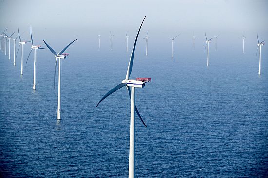
The study of wind turbine blades is crucial as the size of commercial turbines tend to grow exponentially. The blade of a wind turbine could be seen in a simplistic way as a propeller blade. Let’ s make the first big difference here. On a propeller, a torque is given by the engine and the propeller produces thrust force interacting with the air. On a wind turbine, the blade captures the energy from the wind, the aerodynamic forces produce a torque and finally that torque is driven by the shaft to a generator to produce energy. Thus, the design is similar, but the functions are not. Ok, a blade could be simply modeled as a cantilever beam. If we imagine this, it is not too difficult to see that the structural efforts will be concentrated at the root of the blade. Here comes a second big difference with propellers. Propellers are normally short blades made from a single airfoil section, a small change in the airfoil chord along the blade, and a specific twist according to it’s design. (mmmm… I’m assuming here that you understand what an airfoil chord and twist is!). Now if you see a wind turbine blade (mostly for big wind turbines) you will see that from the root to the ~25% of the span (blade lenght) the airfoil sections tend to be thicker than usual. Why is that? Because of the structural forces that the blade needs to deal with in that zone! As you go upper in the span, to the “aerodynamically active” part of it, the airfoils tend to be more like the ones used for helicopters (NACA64 series) or thinner airfoils families like the Delf series DU300 – 250 – 180.
Ok, why all this intro? Just to say yes, while they operate, wind turbine blades deform and they can deform A LOT. The ultimate deformation (and the one that everybody wants to avoid) is when they bend so much that they hit the tower and… end of the story. Moreover, the blades should be as light as possible, you don’t want to waist energy moving it, you want all that energy to go to the generator so, you want a light blade! …but wait, if it’s light it will deform even more! Yup, that’ s why is so important to get a clear idea of how much and in WHICH WAY it will deform.
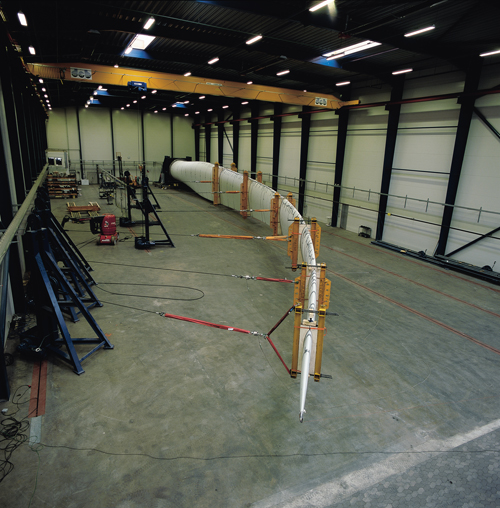
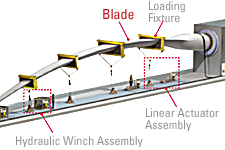
Today’s physical testing on the blades could be like in this picture, where you bend it and measure the deformations. That is call static testing. You could have a very good idea of how the blade is going to behave as the design condition is also a “pseudo-stationary” condition. You suppose a “constant” wind, design your turbine to operate with that wind and get the best of it… and so you could expect blade deformations in the order of the ones you got while testing. Again, very important is PSEUDO-stationary, as the machine is turning, wind is never constant, you have the electrical grid commanding the decisions over the turbine controls, etc, etc, etc.
When you do blade testing with computers, you have many options. The most expensive one (computational resources and time) but the best would be to do a full 3D analysis of the blade. You have composite materials, funny shapes, changes in thickness and distribution of internal structures along the blade so…. Imagine my Blender friends how dense should be the mesh to do a good analysis of what’s going on there! Wait, don’t get me wrong! You CAN do this, and there is always a compromise with the mesh and the level of description you want to achieve to make things feasible! But a good analysis could take a huge amount of time even in today’s super computers. Also, forget about this under dynamic simulations.
Another approach, the one I’m using, is to divide the 3D problem into a 2D problem at the corss-sections of the blade + a 1D problem modeling the blade as a 1D cantilever (and rotating) beam. The 2D problem is very complex to explain in simple words, but you can find a brief introduction in the PDF I’ m attaching as well as in the inside references. The idea is to obtain a full stiffness and inertia matrices for the cross-section (and repeat this process in as many places along the blade as you want/can) This matrices will provide information for the flexural modes, torsional modes, combinations and interrelation of this modes. This is something extremely useful and rather new technique. It could only be solved by finite elements methods (I mean, there are not analytical solutions) and the method is called Variational Asymptotic Beam Sectional technique (VABS) based on a Generalized Timoshenko Beam Model (GTBM).
The 1D model consist now in a dimensional reduction, where the properties of the cross-sections computed before are now assigned to a node in a 1D mesh (imagine a long rope with knots along it  ) . Now solving time-dependant problems or stationary problems on a 1D mesh is orders of magnitude cheaper than solving a full 3D problem. The advantage here is that the information at every node of the 1D mesh corresponds to the 2D cross-section and is very reach. This dimensional reduction technique is also complicated mathematically and you can find a small introduction as well as references in the PDF.
Ok, I haven’t talked about the aerodynamic model but this post will be kilometric and will go far off-topic. The description of it, at the time of my proposal defense, changed quite a bit. Nevertheless, the basis of it still the same.
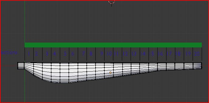
All right, now you may understand (or maybe now you are totally loss) why I’m trying to deal with Blender. The idea, as stated at the first posts, is to post-process the data coming from all the above model. Among the data I can output, I obtain displacements and rotations at the nodes of this 1D mesh (which I called my “Blade’s reference line“ ) and those displacements and rotations correspond to the cross-section on the blade at that location. Solving a dynamic problem I get a set of data for every time-step of my simulation. That’ s why I also said that I have defined a time frame with all the steps. My animation could be think as animating a collar, but instead of little balls, you have airfoil sections (yeah yeah, interconnected and looking as a single solid body, not like an accordion).
Ufff! That was long. I hope you could get now a better idea of the general picture.
I think this forum and this post won’t be a good place to start discussing the theories mentioned in the PDF or in the above introduction. The intention of all this is to apply Blender (and python scripting) to a project. Take it just as that and let’s leave this anecdotic long post as the catharsis (uops! …general description? ) of a specific application.
Thanks for the interest again to all of you reading this!
Lucas
PS: I couldn’t attached the PDF here due to limitations with the file size in the forum. I put it here
Attachments
mmm… I did a big post a couple of hours ago with a long description, but it seems it was not published. Maybe it is under revision 'cause it is too long? Anyway, I have a copy so if tomorrow I don’t see it posted, I’ll re post it in 2 or 3 parts.
Thank you, I think I have understood the “beam” approach to this blade (it is similar to the 1D “beam” simplification, used sometimes to model the wings of small aircraft).
So there will be two sets of input data (ASCII text files):
- the “non-deformed” geometry of the blade (all sections, as the airfoil data, are described by the same number of vertices, aren’t they? I think I would be very simple to generate the mesh model from this data, you do not need to make any specific “skinning”): section number, height (on the blade), x, y-upper, y-lower (let’s assume that the point of the Blade reference line - the origin of the section - is at x=0, y=0. This assmumption would be wrong, if the non-deformed blade reference line is not a straight line. In this case we need to specify its x, y per each section). This is very similar to the format, you have proposed on the previous page, in the post #5. Just the “header” of each section:
Blade NREL5MW intermediate airfoil # 0026 @ 0.7717
has to have at the begining a keyword (it can be “Blade” - but it has to be a fixed text) which would allow the program to immediate recognize it as the begining of a new section. This line would contain the section id (#0026?), the height (@ 0.7717), and the eventual information about its x, y origin, if the blade reference line is not a straight vertical line…
- the airfoils deformations: section number, translation (x,y,z), rotation (Euler angles? Quaternions? I think that quaternions are better): one file per each frame of animation? We can also to interpolate the deformations “between”, linear or by the Bezier curves, but for the larger differences of interpolated rotations it may give some strange results.
Using these data, the Python script has to create in a Blender file the mesh model of the blade, and set up the animation sequence. It would be ready to play…
The “static” content of the Blender file would contain the lights, background, and all the other “artistic” stuff needed to create a properly looking renders of this animation.
At this moment it seems quite simple.
Let’s begin with the geometry (point 1). Is the proposed format OK? If it suits you, could you give us a real sample, to test the script that would generate the mesh? The key point is the easiest way to apply to this mesh the deformations from point 2, but I will try to propose something…
very interesting subject
this will lead to the desing of what windmill size in terms blade size and of Megawatts ?
also you seems to say that all these algos cannot be resolved on PC it has to be done on a Super computer
on ly general note i did not see is the effect of bumps on the blade surface which could increase the Efficiency of energy transfert
Some research where done on this subject at CNRC a few years back studying whale’s fins
i mean nature has a way to solve problems which is amazing and usually simple!
can you give us the first part and what the data is and what to do with it !
here i’m assuming your running blender on a simple PC and not on a supercomputer
don’t know if it will be able to handle all data’s in a realistic time may be you could use a PC farme to do the rendering !
Does ProE do a lot of stress analysis and flow dynamics already? Are you looking into writing your own algorithms?
by the way i wish gyou ood luck with your project
if you can find a way to use PC to simulate this engineering (Mech/structure problems with finite elements)
instead of using Supercomputer i guess it would be a step foward in terms of simulation/modelisation
and would help make the design of windmill blades or other propeler types faster and easier by using PC
I’m stil trying to find if there are any simple Python scripts to do simple Finite elements modelisation for simple beam!
mind you i’m not into mech/structural design
but still an interesting in this subject
and even more if it can be use in blender
so bring us your first step which i guess is the blade model in blender may be
or give us what has to be done as a first step
I have quickly checked the possibilities for applying mesh deformation, and finally come to the conclusion, that an armature is the best solution. It will contain disconnected bones, one bone per each section, and each section will be defined as a mesh group. It seems that it will be relatively easy to generate such an armature programatically.
RickyBlender, we have to process the results, not to make the main computation.
(BTW:
- the beam model is an simplified one, that’s why it does not require a “supercomputer”. You underestimate the power of your PC :).
- the skin of the whales actively controls the boundary layer, which is still not possible for human technology, at least in the practical applications).
Hey!
Nice to hear from all of you. First of all, commercial codes now a days doesn’t allow the type of analysis I need to do. As I said, yes, you could do a full steady state 3D case , but it is not what I’m looking for. Also, great thing there are no commercial codes doing this! Otherwise my thesis proposal would never have been approved as something innovative!  About the super computers and standard PCs, yes you can do this on standard PCs too! It will take longer, but you can still do it of course.
Ok, going to business!
Witold, All your assumptions are right, but I can tell you that it could be even simpler! I’ll tell you why:
- The data I posted contains only XY data, but you are totally right! The blade axis could be a non straight line!!! This is SUPER important as blades can be pre-bended, contain a swap back, etc. What I can do is to process the coordinates of the airfoils multiplying them by the corresponding rotation matrix which will output the coordinates in their real final position. I mean, only by loading airfoil after airfoil, you could have it positioned along the blade axis and with the corresponding twist. I think that would help a lot. What you think?
1b) The 1D mesh (blade axis) could be imported and positioned exactly in the same way as the airfoils, instead they will be just a collection of XYZ coordinates in a form of a line. It is important to note here that I could have, for example, 20 blade sections, but 150 points on my 1D mesh. Why?! Before the solution of the 1D problem, the calculated property matrices for the 20 airfoil “stations” are interpolated for the 150 nodes of the 1D mesh. Again, details of this process will be totally off-topic if discussed here, but it is important to note that my blade “model” could have 20 airfoils and the 1D mesh (where displacements and rotations are computed) could be for 150 points. This also simplifies what you said about interpolating later displacements and rotations!
- You don’t have to worry about the “deformed” coordinates of the airfoils! Great second news! Why? Deformations and warping are recovered after the solution of the 1D problem, for every section. For This blender project, let’s say that my intention is to animate the 1D mesh surrounded by the external real blade “skin”. It would be like animating a whole snake just by doing it by it’s skeleton. That’s why I thought at the beginning “bone animation”. The “deformation” of the blade should follow the rotations and displacements of the blade axis. This is not totally and perfectly accurate, but for the sake of showing what’s going on a dynamic study, with 3 displacements and 3 rotations at, let’s say 150 points along the axis, is more than enough. To compute stresses, real deformations at every section, etc. I wouldn’t use Blender by now.
OK, once again I’m super happy to find people like you guys wanting to help this Blender noob here! Thanks! I will try to post a complete package with the ASCII files for the airfoils and for the blade axis as soon as I can.
See you around!
1- Whale’s fin
this has already been done at the CNRC and verified on a practical point of view!
and it works but very modern only 1 year old
2- I’v seen a script for 2.5 something to make the shape of wings !
don’t know may be it can be use !
i’ll check out this script but it does not have animation
3- data
can you upload some sample files of data for the different parts so we can begin to look at it
like one file for the chord or center line i guess something like 150 points that should be easy to do
The 1D mesh (blade axis)
then may be the first cross section which i assume would be the first frame for the simulation
or the first frame has all 20 sections may be with a certain shape like twisting and bend!
not certain how you want to proceed here
4 - do you want this as an addon with a small panel in tool pro section may be?
i can begin a small script like that easy to do !
I am just curious, how this blade will be deformed under load (maybe because I have studied on a faulty of similar profile :yes:).
Ricky, the add-on you have pointed generates airfoils from the so-called NACA family. They were widely used in the middle of previous century - really a great, good family. This case is different: the airfoil will be our input data of point 1. We have just to generate a mesh from it.
santasemilla: I have exactly the “snake” idea of the blade reference line in my mind, writing this proposal, as you have dscribed. So single line of the data file from the point 2 should contain:
#ordinal number of the reference line point,
its current location (x, y, z)
its current rotation (a quaternion)
the frame will be identifed by the file name?
We will need also a “zero frame” file with the geometry of blade reference line for the undeformed blade (could we assume, that the points on the undeformed blade line have no rotation?)
I think, that the simplest way to couple it with the “skin” will be to interpolate the additional sections between the given airfoils, to obtain a 1:1 relation between the reference line and the airfoils of the mesh. (The script has to do it, adding to the mesh additional cross-sections on the level of each reference line points) Otherwise we can have troubles with realistic deformation of the final object.
well if you do it with bones and let say you have one frame with 20 sections
you can assign verts group for each section and have an armature with 20 bones then apply a rotation localy and may be a translation
for each bone
then the weigth factor will adjust automatically the deformation for each section and should be smooth
for the next frame you can readjust the verts location then change the bones rotation and it will self adjust for these new verts locations!
if that’s the idea here!
Ricky, you are right. I have proposed to generate a section per each blade reference point, because it seems to me simpler and I think it can give better results, than to play with the weights, having, let’s say, 3 bones per each original section. I have just checked, that you can freely control rotation and location of each disconnected bone. Here is my test file: blade.blend (369 KB) (just three sections and three bones, just to check if it works)
ok but he armature 's bone line have to follow the center line of the prop
i think you still need to define vert group here!
or if you don’t use vert group how do you change the location/ rotation of the sections?
so we need this line from our friend here!
please load up some data file here for the center line and may be one or 2 frame of data 20 sections per frame or less
to start with to begin testing
but how do we get the continous shape of the whole prop here
we have to do it manually from each section to next section?
by the way is there a way to copy the name at the top of a post without the color problem?
in fact, the bone line of the armature will be the center line of the balde - because the propeller sections will have not any specified origin point.
Examine the mesh and the armature in the blender file I have enclosed in the post #36. You will notice, that there is a vertex group per each bone.
Yes, I think that the Python script has to create the mesh - it is not so complicated :).
In each point of the center line (let’s say 150) we will have to place a bone.
The additional operation will be to calculate coordinates of the the arifoil section of the blade, that matches (1:1) the position of the bone. It could be calculated as an linear interpolation of two neighbour sections, got from the geometry file (Let’s say that we have a section at Z0, another at Z1, and the bone is located at z, which is Z0<= z <= Z1. The coordinates of the section that corresponds to bone at z can be calculated as v = V0t + V1(1-t), where t = (z-Z0)/(Z1-Z0)). From these vertices we would build the mesh, naming each section as a vertex group having the same name as the corresponding bone. So per each reference line point the script would have to perform following operations:
- create (by duplication) a new bone and assign it an ordinal name (like “026”)
- identify in the input geometry the “neighbour” sections
- calculate the points of the new section, which corresponds to this bone, from the identfied input geometry
- use these calculated points to add another “collar” of faces to the mesh of the blade
- make from these new vertex loop another vertex group and give it the same name, as the bone (like “026”).
The input geometry data could be kept in a dictionary, where the Z position of the section would be the dictionary key: {Z0:[V0], Z1:[V1],Z2:[V2], …} because it would make easier the lookups
Then the input data from point 2 would allow to set the key position and roatation per each animation frame.
i did look for the V group but did not see these in file
i’ll check again!
but don’t think you need more then 20 bones one per section in any case he does not have other loc/Rot values so not very usefull to have more then that !
one idea here why not add some V color function of the rotation so you can see a better representation of the rotation in viewport on function of the translation may be!
not certain with dic never really use it a lot before but might help!
another thing here is that this could be made with Nurbs circle extruded or Bezier extrude may Be
at least no problem to make faces!
then transform into a mesh and cap it may Be
then play only with bone weight and Rot/Transl
ounce the basic model is made for the prop only ting left is to re adjust the Rot /Loc for each section!
if you have an idea start it for the basic shape for the whole prop which can always be change afterward and add all the bones from B1 to B20 with V vgoup and Vert color may be
that part should be easy and only done ounce i think for a prop model
after only thing left is the Rot/Loc for each section per frame
i’ll try to come up with a little script for tool pro with an operator to read file and do it
salutations
got this model i did here with 20 sections
let me know what you think
ok did not do armature and V group but it’s basic shape unless he can provide us with a given shape
blade2251.blend (282 KB)
ok got a tool pro panel script with a simple menu for different actions
got to add the file read operation in this later waiting to get more data so we know what to do with it
prop251.blend (345 KB)
made it with CC licence
added your names guys
you can add more doc if you want in it
try to change the version at end of file name and script name if you make a new version
have fun