Well,
After many many days of my last post, I’m here to add part of what I promised. I’ve been very busy with other things and my plans to submerge my head into Blender had to be postponed… and will be a bit more unfortunately. Nevertheless I keep preparing the things for that time and work on the Matlab side of the project with the things that I will need to pass to Blender.
Ok, here we go! In the zip file you will find basically the skeleton of a test blade. This test blade is made of 23 airfoil sections, every file contains the structure mentioned way ago on the sample data:
-First archive line: A description. Let’s just don’t pay attention now to this, let’s say that in the future we can put some information here as “section # out of xx” etc.
-Second to last line: This are the X Y Z coordinates that define the airfoil in the exact position on the blade. With this, after loading all the files the blade will be defined, including twist and, if corresponds, the initial design deformations (in this case the blade axis is straight, so don’t worry.)
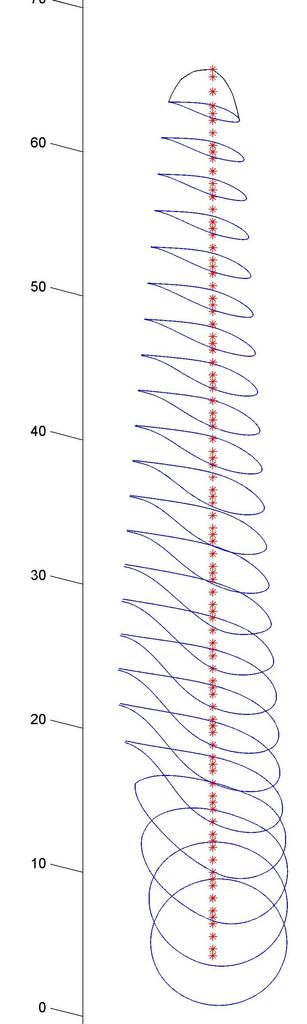
In the same way we have the axis coordinates. As I just said, the axis is a straight line so for this case only the Z coordinate is nonzero. Here, instead of 23, the points are 93. In the figure I’m attaching, every node of the blade axis is marked with an “ * ”. These nodes are the ones that later will be animated! So yes, you guessed it, the “vertebral column” that we talked about before is this axis. Bones for the animation should be defined by the segments from the coordinates.
The last file in the package contains the coordinates for the blade tip. What is this?! As the blade is a solid that is going to be “extruded” along it axis, there should be a way to define how it ends! If you see the example of the boat I used to describe the idea in the OP, the last cross-section, the after-peak, is inclined to define the way the boat ends. Here the case is a bit different, I know. The boat is an open solid (mesh), here the blade is closed. Here the blade tip is perpendicular to the cross-sections and “extruding” of the blade should have this exact shape at the end. …How I do that in Blender?? I have NO idea. Couple of thoughts:
- Easiest: If it’s there a command or function under modeling and the problem is easily solved but I just ignore it from my lack of Blender knowledge… just forget about this discussion.

- Maybe the blade tip could be part of a second “auxiliary” solid to then subtract to the main blade and get the final shape. Autocad/SolidWorks ideas coming back to my mind after long long time. (mmmm… am I clear here?)
- I can re-define the airfoil coordinates so I can load them in two halves. Let’s say a bottom and a top one, as if the final blade were made out of two molds (…hehe that’s how they make it in reality!). In this way, the blade would be exactly the same as the boat example, but with a bottom and a top “hull” hehe.
Anyway, by now, I’m just uploading the data, otherwise I’m delaying too much the progress here.
If all is loaded into Blender, you should end up with something like this:
(sorry for the awful perspective! …Matlab’s fault! Hehe)
Well, here the zip file: Blade2BlenderTest.zip (117 KB)
Note: I almost forgot it. You will see that some airfoils are not closed at the trailing edge (the tail). This is not an error. Thick airfoils could have a blunt tail so don’t be surprised if you see this. …mmm yes, again, I don’t know if this could complicate the extruding, hope not. If it does and we need to close it, just let me know.
Note2: All units are in meters.
I have to thank again all the help and interest you are providing to this project people! I really appreciate it.
See you around!
Santasemilla