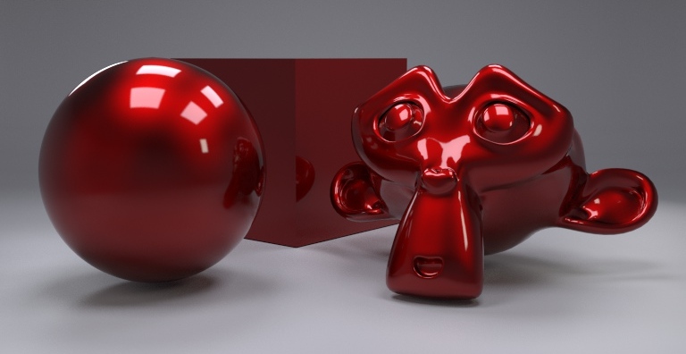
As you can see, I have changed my usual test scene. I’m using one blender test scene, made by @Tuqueque. This file contains three scenes. You must select the one for clothes that you can see in my image.
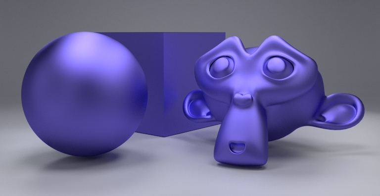
The test scene is very important and must be suitable for the material you are looking for. See how this material does not stand up in my usual scene:
Thanks a lot for all this. I’m learning tons! Keep them coming, but I really take my hat off to you for putting the effort in and giving it to us for free!
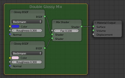
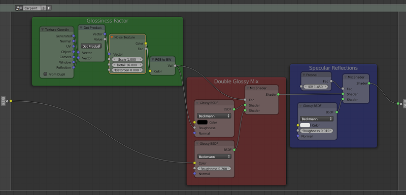
Don’t look for an explanation of the glossy factor setup. Just I tested several options and that dot product shows an effect I liked. Apart from that, I used a double glossy mix, with the color parameter and pure black. I wanted a dark color back.
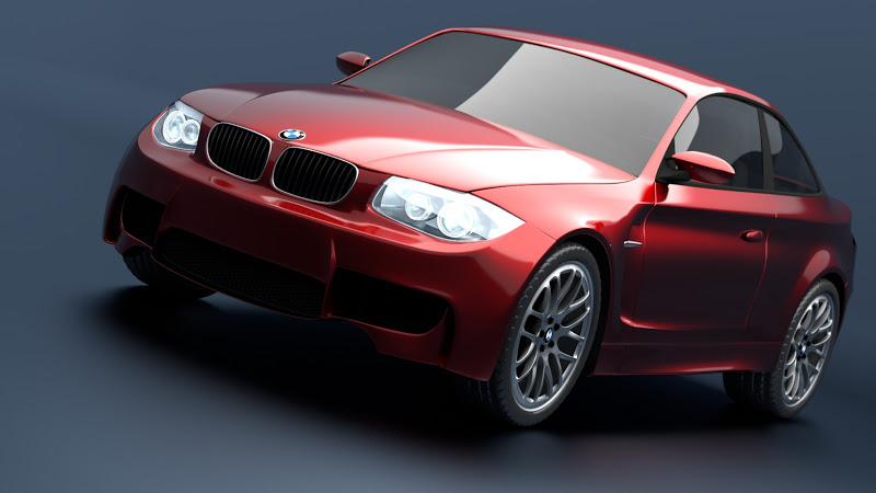
In the next post you can see this material in the mike pan bmw model.
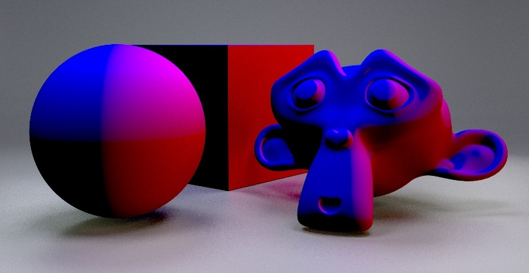
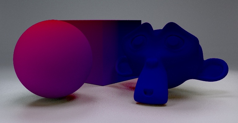
what about the incoming one you get 1/2 red 1/2 blue
i get redish and almost black!
edit
i’v uploaded a new file showing all attributes in geometry node
not certain it is usefull
but would like to undertand the effect of normal incoming and other attributes here
i’v uploaded same file but corrected
and i adde all the var for the geometry node
i know the Backface does not really do anything with vector
use to control emission on 2 faces!
seems also that real normal is for mesh without subsurf !
Thanks, but I was actually referring to the previous examples where you are using node groups.
I have figured out how to create and edit node groups, but I am unable to figure out how to add the things that are embedded in either end of the node group, that function as the input and output.
In the jewelry gold example you have five on the left, and one on the right.
How do you add these?
Ok, I didn’t understand it. You can use the same way explained, simply drag the socket you want to be your output/input and drop it in the border. Or you can make your material without groups, and when it is finished, you only need to select all the nodes you want for your group (pressing SHIFT) and then press CTRL+G to create the new group. A button asking to you for creating a new group will appear in the node editor.
You can download one of my test scenes in this link.
Basically I use:
Four square meshlights located in four corners, with different strengths and sizes.
One square meshlight above. This is divided in four faces with emission material and others transparent. Instead I could have created four meshlights.
All enclosed inside a box.
Very importat for my lights is they only emit light through one size. The other size is transparent. See blend file of my link.
With this setup the scene is a bit dark, so I have preferred to use some scene compositing and increasing the film exposure instead increasing strengths. Again see my blend file. This way I think materials look better.