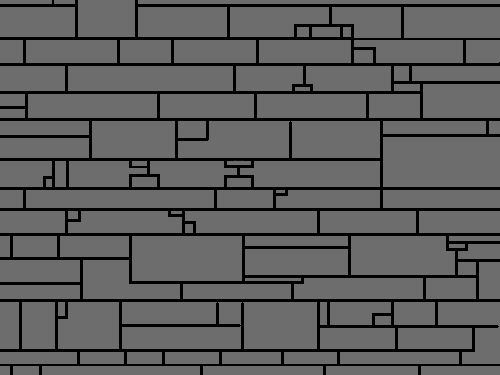
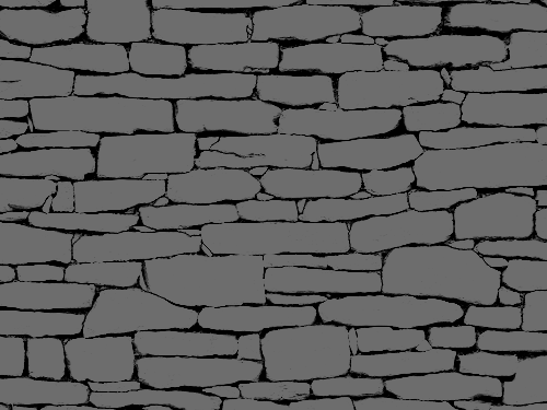
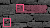
In between the main branches are smaller branches with more frequent splits.
These splits visually appear as a T, Y, or K.
These splits can be further simplified as a single split (a T). When the angle at the intersection of the T is altered, it appears as a Y. When the branch is immediate, it is a K.
Depending on where they are, they either form cracks in a brick or define a new brick.
It occurred to me these features are similar to procedural tree generation: branches with variables such as turbulance, split angle, and split frequency (and thus proximity). It also bares semblance to fracture.
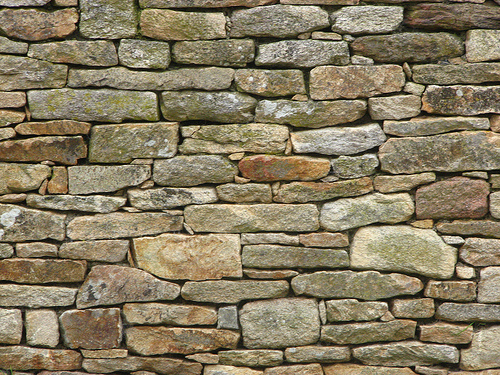
To test this theory, I looked at otherphotos to see if it held up.
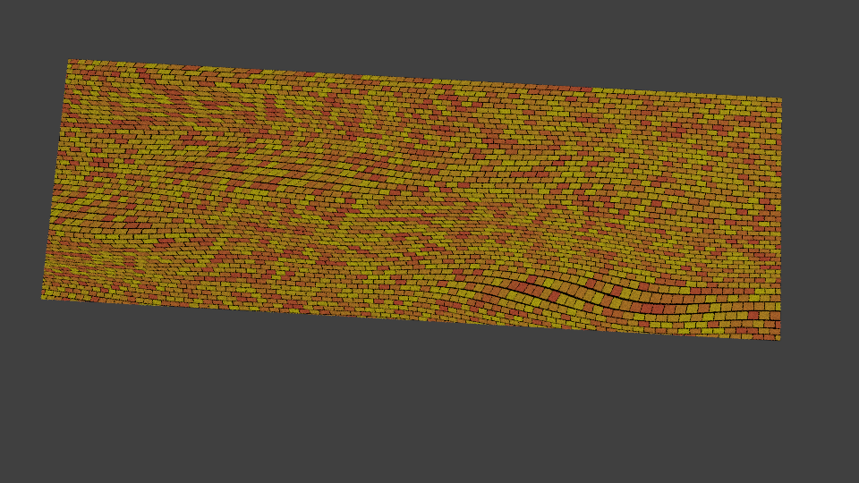
If the first branch split frequency is high, split variable low, and turbulance low, and rotated with UV mapping, you’d get straight lines with regularlt spaced splits like this:
If the first branch split frequency is high, you’d get something like this:
Other facets I noticed:
Bricks are distinctly different in tonal pattern and possibly color.
Aged bricks may have another layer of grime or erosion that blends them together.
Brick depth may be calmly similar or wildly turbulance. Some bricks are flat, while others are jagged, and everything in between.
Capstones also vary in surface turbulance
Larger stones are typically (but not entirely) employed where walls turn or holes constructed.
How to program this procedurally? I don’t think it can be noodled with nodes, but then again, there are some clever folk in Blenderland. If not, surely a script could make short work of these parameters.
I tried those options and failed to get the desired results because the brick and checker have no provision for creating branches. At best, you’d have to hack it together with UV maps for each branch you want to connect. In order to achieve procedural branching the way I’m describing, I think a script may be the better solution. However, I’m open to being proved wrong.:eyebrowlift:
If I want to create a city made of stones or bricks like an Aztecian pyramid or English castle, I don’t want repeated patterns, so modelling and baking is out. Textures would be huge and time sunk on a menial task placing the branches randomly a million times. However, if it could be created procedurally, then memory is lessened and time spent on more important tasks.
I don’t know anything about OSL, but I will look into it. I’m not a programmer and I suspect my introduction to the Weber / Penn approach to describing trees used by the tree generators may need closer scrutiny. Maybe if I review the tree addon code and/or contact the author, I might be able to make progress. Thanks for the heads up.
with cycles you do have an option with info node to add some randomness to certain variables like location ect.
but don’t think this will make super define stone like you describe!
@ion8: interesting problem I agree there us some resemblance with tree like structures but even if you could somehow codify it I doubt it would be a feasible approach for a shader because basically for each pixel we would have to generate the whole tree to determine in which part the pixel was (OSL has no global shader storage).
But another way to look at your brickwork is this (and that would still be tree-like in its self similarity but straight forward to implement in OSL):
start with a basic pattern of bricks, that is rows of bricks, each row possibly a different height, each individual brick a different width
assign a random ‘pattern’ to each brick. The pattern comes from limited set, for example divided by four, chipped corner, etc. The result is that each set is divided up in smaller bricks
maybe repeat this for the newly created smaller bricks
The result would consist of a pattern of large and small bricks, yet still be rectangular, but by distorting the input coordinates (like rickyblender showed) you can break this rectangular pattern.
I will have to think about it some more to see if this really is workable
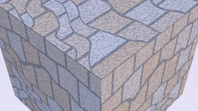
@Ion8: To show what I meant in my previous post I cooked up some code to illustrate the concept of creating irregular stones and replacing some of them by smaller patterns. I documented it in an article on my blog (where you can also download the code for the OSL shader) but shown below is the basic pattern I had in mind:
Of course this is still far from what you have in mind but I think some of the basics are in place and I will certainly explore this approach some more.
Thanks for the feedback, Michel. I expected you’d have insight, but a prototype and a blog entry? Above and beyond the call! Kudos.
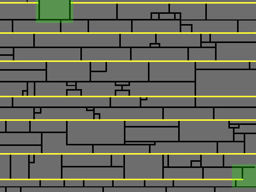
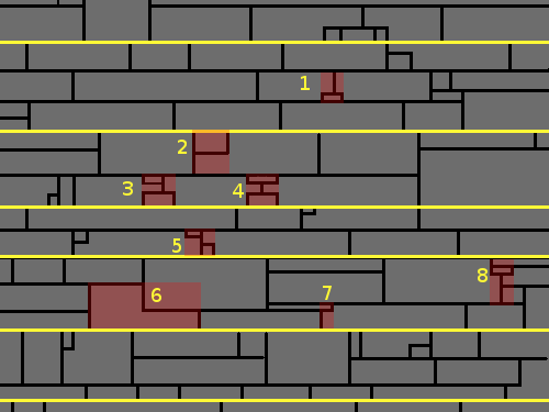
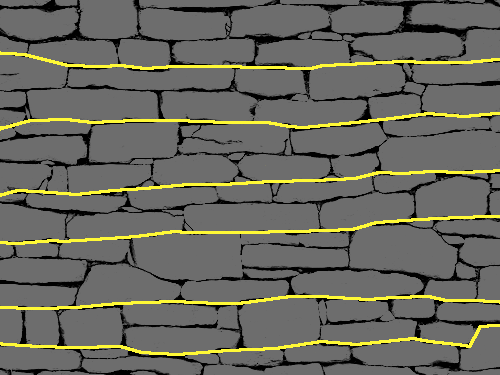
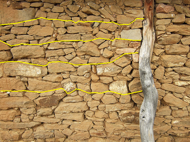
I like your idea of thinking of each rectangle as a container for possible fractalizing. I’d be curious if mathematically distorting the rectangles and adding turbulence could match the basic container enough to appear life-like. I imagine twisting the layout via UV is useful for broad strokes, but lack knowledge of brick edges enough to provide details. Another trait I noticed is a brick may be positioned that it breaks the horizontal row line completely, as seen on the yellow line in the lower right of the image.
@Ion8: I just enjoy interesting problems and I liked your clear illustrations
You might be right that distorting the coordinates might not be adequate. I think it might be useful to add small disturbances but larger distortions might probably simpler (and better) to implement by the script itself (for example by moving the four corners of the generated rectangles a bit in random directions. the math for the fractal infilling becomes a bit more complicated though). Anyway, we’ll have to experiment
YAbout stones popping out a horizontal row: I think that would be quite difficult to do, but on the other hand it remains to be seen how much it it needed to create the effect of loosely stacked stones that you are after.
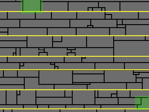
However, if we move the main row lines, it solves itself.
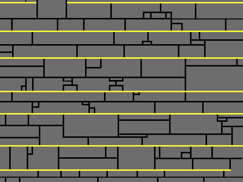
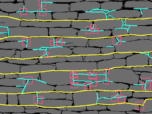
I see two rules at work here:
A row split into 2
A row split into 3 has a retangle that divides 2 rows
A row could be 4 high, or 10 million for that matter. May as well be user input. However, these rules would not work for long, horizontal spans because the pattern would be obvious and nullify the entire point of the exercise.
However, there is another problem - smaller rectangles that cut into bigger rectangles that become L shapes.
Another way to look at it is the splits resemble a T, P, or H if they are close enough. Sometimes the shape is inverted. More importantly, most of these smaller cuts are not rectangles in the photo, but V’s. Coding would need to tag and distort them specifically.
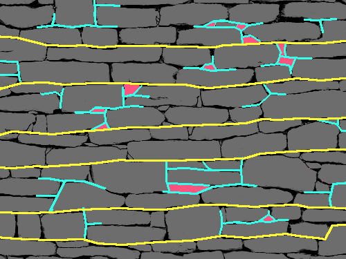
After all was said and done, I manually distorted the shape to see what it might roughly look like. Intelligent line width would be needed, especially for intersections.
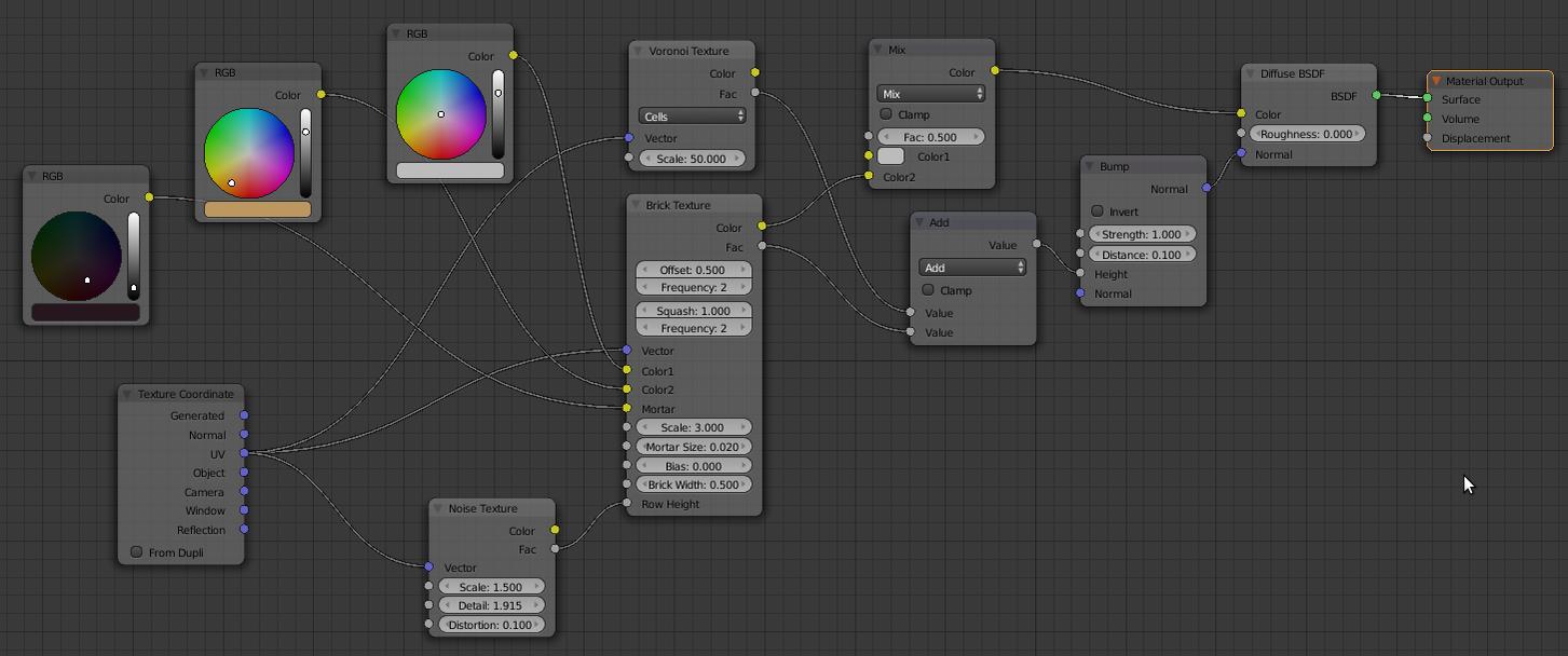
Just reading through this was thinking… Brick Texture… and Voronoi Cells Texture Branched together with a Math node (or color mix node) into one… The Voronoi Cells would give you some nice ‘Y’ cracks… the only problem then would be that there is no control on how wide the crack can be made in the Voronoi like you can with the Brick Texture…
When it comes to using the Voronoi texture, you can’t easily use it to create the cracks because of the functionality removed as part of a texture code cleanup (during the Cycles branch days).
Back then, it was possible to easily create cracks by using the noise texture and setting the type to ‘Voronoi crackle’. Nowadays you could (perhaps) use math node and vector wizardry with the Voronoi node to get close, but I’m not sure how you would do that.
It is possible however to manipulate vector coordinates to distort image textures, so you may not need to do it manually in a paint program.
I think broad distortion is fine, but it can’t possibly account for every split. Manual UV tweaks are a dead-end. The only solution I can think of is a split parameter on a shader. I’m not even sure a more controllable Voronoi would solve this particular problem, but it does bring up an interesting question - what would it take to get that code back in?


 I agree there us some resemblance with tree like structures but even if you could somehow codify it I doubt it would be a feasible approach for a shader because basically for each pixel we would have to generate the whole tree to determine in which part the pixel was (OSL has no global shader storage).