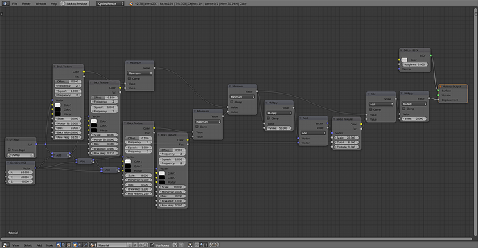
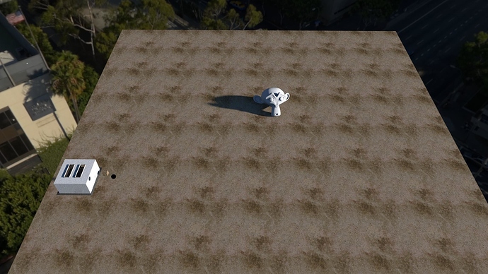
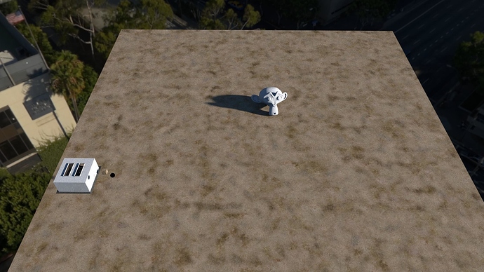
I haven’t found much very good tutorials. If beginning, they may all prove useful to some extent, keeping in mind they may not be very accurate (it’s frenell, not freshnell or fritzschnell or whatever :D, not to mention diffuse metal, diffuse roughness, or that anisotropic is not just about metals). Also, don’t restrict yourself to Blender only. I have learned everything myself (with help of Secrop above and others off course), but no courses or tutorials - only experiments. In fact, I wish I paid a bit more attention back in school (ages ago), especially maths and physics, because some knowledge is extremely useful. Both in terms of figuring out stuff for yourself, and for being able to read and anticipate results when implementing things already done.
Make yourself a favor and build yourself a big library of math functions that can be handy, they can be linked into your startup file (although I have to make all local if I plan to take it to work, haven’t figured out how that stuff work yet). Stick everything in a dummy material and remember to fake user everything.
Although the color ramp offers good flexibility, it lacks ability to be controlled. Stepfunctions (linstep, smoothstep, smootherstep with numeric inputs which can be controlled) and fLerp (same as color mix node in mix mode but on floats with visible numeric inputs without additional nodes) are key to all my library stuff (both have many users in my function library).
Remapping Coordinates is a utility node you can make if you need other coordinate systems accessible to procedural patterns. Such as spherical, cylindrical, disk (and compounds of these, although it’s much more useful to compound finished result than to compound the coordinates), pyramidial (useful for simulating light projection mapping, but we’re getting proper UV for lights soon so may diminish in usability) and so on.
Custom Mapping Node is another must to create (see Bartek Skorupas tutorial on this). Check against original mapping node that it delivers the same result when everything is combined (to ensure proper order of execution if several is combined in a row). I have no idea what the min/max options are supposed to be useful for, I prefer to simply have a mask output as well. Possible improvements could be builtin “texture coordinate blur” and skewing controls. The big point of this node is to be able to control everything using connections and expose things to a node group interface (very lacking feature in Blender).
fInsideOutside is also a nice utility, which has above and below masks, as well as above and below keeps. It has an input value and upper and lower boundaries.
fSplitter is similar to above, but it only has an input and a single splitpoint, with several outputs you may want.
fValueNormalizer is critical if you want to explore the world of Musgrave texture, possibly also others. This is a fantastic texture which can have tons of values outside the visible 0-1 range. Input value, Measured Min and Max which you tweak in preview mode, and a Preview On/Off switch are nice features. In my own I let (in preview mode) n<0 show as black, n>1 show as white, and 0<n<1 show as mid grey. I’ll tweak the min and max values until I get all grey and turn off preview mode (if I’m working in visible range). Although not always 100% intuitive what goes on, you can also preview the musgrave through a bumpmap node and look at the normal modification that would take place. It gives an indication of the pattern hiding in it even if you have to scale the result to make use of it for color and value based texturing. Always add some random vector to the input coordinates when using musgrave, as some weird stuff may happen around 0,0,0.
Make also special versions of math nodes that “fail” when using object coords. Notable example is modulo, which you may want to have a version that is continuous around zero. Or be prepared to add some random vector to avoid being near 0.
Plan to have your node group expose only 0 to 1 ranges, and temporarily use color mix fac input to connect it up. It is a slider type rather than a value type and you can have much better slider control when tweaking the exposed value. In terms of math, it is much easier to predict what will happen if you stay within this range. Of course trigonometry should have 0-2pi, but only inside the node group - keep exposing it as 0-1 (same as anisotropic rotation). The only time I use value node is for pure on/off switches (connected to a math round node inside). Or rather, I wish I knew this when I started, now I can’t even find all users so I could replace the slider control with the slider type, and they’re stuck with “uncontrollable” value inputs instead 
It makes sense to combine some of the float math functions to operate on vectors (such as vRound, vLerp, vModContinuous, vScalarMultiply, vMagnitude and so on).
Sometimes it pays to think out of the box. I could not make a version I found online for atan2 to give proper results in the crossover angle (was a way back, so I could have gotten it wrong). For this, now I use gradient texture set to radial mode, and it works perfect 
Do stresstests. Some function may have different formulas that ends up with the same answer. Do you want to do n*n or n^2? In this case shader compile may handle it automatically (don’t know), but other cases such as vDistance (euclidean distance) it may not. It also involves what kind of node/code you prefer to see.
Use nodewrangler. Did I really have to say that? 
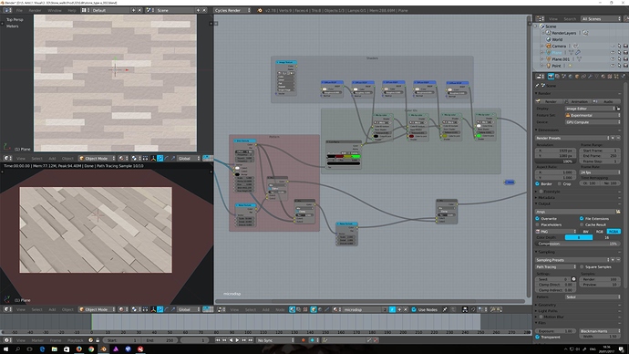
For testing, I suggest using a small preview window. For F12 renders, use a small output window (replacing the preview if you can). The UV window output lets you measure the values. Not sure if this was updated, but if the values differ in the UV window, switch to none in color management to have the non corrected values shown. This is priceless for debugging. Just don’t forget to turn it back on when rendering the full material or scene 
For shader trees, plan ahead. Marble should have subsurface scattering, but do you really need it on a marble tile floor? Do you prefer to obtain randomness from object info (requires more objects) or create random color output from within the material setup (one object, but takes a long time to learn and setup in some cases).
Be sparse. Don’t add a noise detail slider if it’s not really required, and don’t pump the detail up more than absolutely necessary, and try to randomize/scale the color output separately for the noise when you can instead of adding lots of noise nodes. Texture generators, especially on high detail, can be way too heavy to render, especially when combined and/or plenty of them. Similarly for the actual shading stage, try to do as much as possible within a single shader instead of combining five glossy shaders. If all that is happening is color change going into diffuse (usually diffuse roughness is ignored), control the mixing with a color mix node rather than a shader mix node. You want as few shader calls as possible. Let’s just say that a layered shellac is extremely time consuming to render (many glossy nodes required).
So, not pointers to resources, but things you should prepare yourself for when going down this road. If displacement is what you’re looking for, I would expect better results trying to implement irregularities compared to implementing repeating patterns. Pattern generation, although fully possible, can be a pain trying to wrap your head around - especially if others made it. Irregularities are more experimenting until you are happy enough. And I’d like to stress that use displacement only for the major features, don’t ignore bump and normal mapping. True displacement is still too heavy for me to use effectively. For regular patterns, get your linstep, smoothstep, and smootherstep functions working - they are key to pretty much everything. Don’t jump straight into 3D patterns (although some are pretty easy). Get the basics done in 2D. Then the advanced done in 2D. Get more variants done in 2D. Then jump onto 3D. Then just stick with the 2D when you figure out 3D is way too hard or give you unexpected problems 
Yeah, huge wall of text right there. Now… Bedtime…


