Ok, in an ongoing effort to disprove “there are no stupid questions”, I am going to try…
I have a simple rod shape made of a carbon fiber weave (think fishing rod or pool cue shaft, or javelin). I’ve done quite well in blending a number of shaders (anisotropic and principled) together so that the light hits the material and reflects the various directions of the fibers from different angles. I have mixed the shader nodes together, applied some nice noise to create irregularities in refraction so it looks “used” and has finger smudges etc…
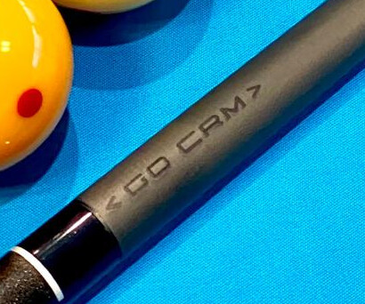
BUT, I would now like to simulate an laser-engraved logo on a specific part of the shaft. It should just “roughen” or depress that part of the material with the company logo or other text.
Ive searched tutorials, youtube, these forums etc. and feel like this is such a common thing, I must be going full NOOB.
Do I need a second UV map on the same object (rod)?
Should I try to use an alpha map on all the other shaders to exclude it there?
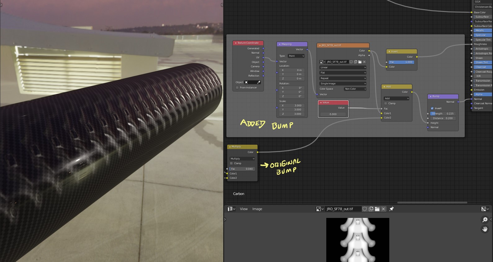
There are several ways to approach this…depending on your node tree…you could add a second normal / bump map a mix with the one you may have…like if the carbon has its own ( the one I made does)
EeVee screenshot…
Since this was a pure Procedural I could add in another mapping / coordinate group to control size…also this could be with a displacement for cycles or a displacement modifier with texture for EeVee!
Make sure that if you go the Bump and or Displacement be sure to blur the Logo so that it blends well ( most use a gaussian blur on the greyscale once or twice.)
You can also bake a normal map with the logo and add it to the normal input on the Principled or Bump Node…there a just a bunch of ways to go about this…
Hi RSEhlers, Thanks for the reply and tips! I had gone down the route you describe in the last tip, but here is where I run into issues.
There are 3 primary shaders (principled and anisotropic) that mix into the final effect. They are mixed in varying amounts to achieve subtle relfective/refractive effects. To which of these would I even apply a normal/bump?
Secondly, the logo only should appear on a small piece near one end of the object. The procedural patterns repeat all over, and are tuned optimally now. The logo just appears on a few faces of that mesh…
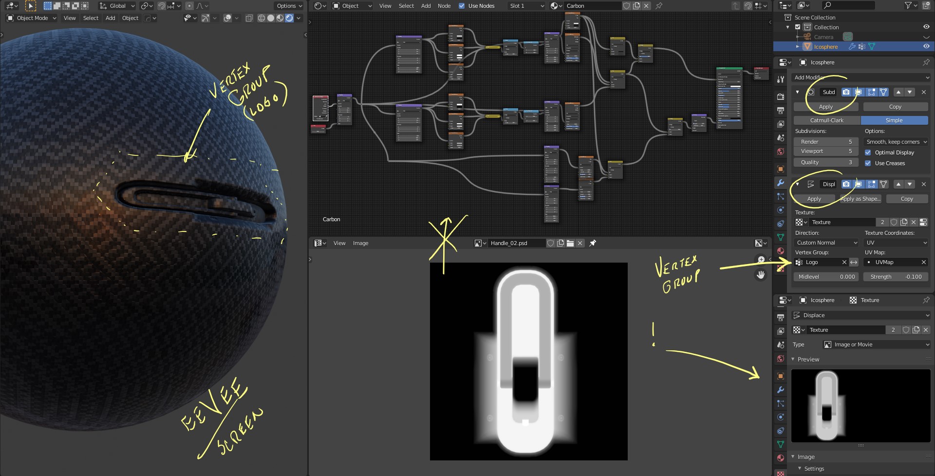
ah OK…I would really need to see your complete node tree…but I do have a quick idea…and that is to select the location for the logo on the mesh…and set it as a vertex group, name it LOGO…then Make sure that there is enough subdivision on the part…so that you can add a TEXTURE in the Bottom Texture and a Subdivision Modifier if not already used… add a Displace Modifier…In the displace set it For UV and pick your Vertex Group also…
Select the vertex group…and open UV editor add your Logo image and fit the vertex group UV to the Logo…( it should be in there as soon as you enter if you used a standard Cylinder to make the rod…
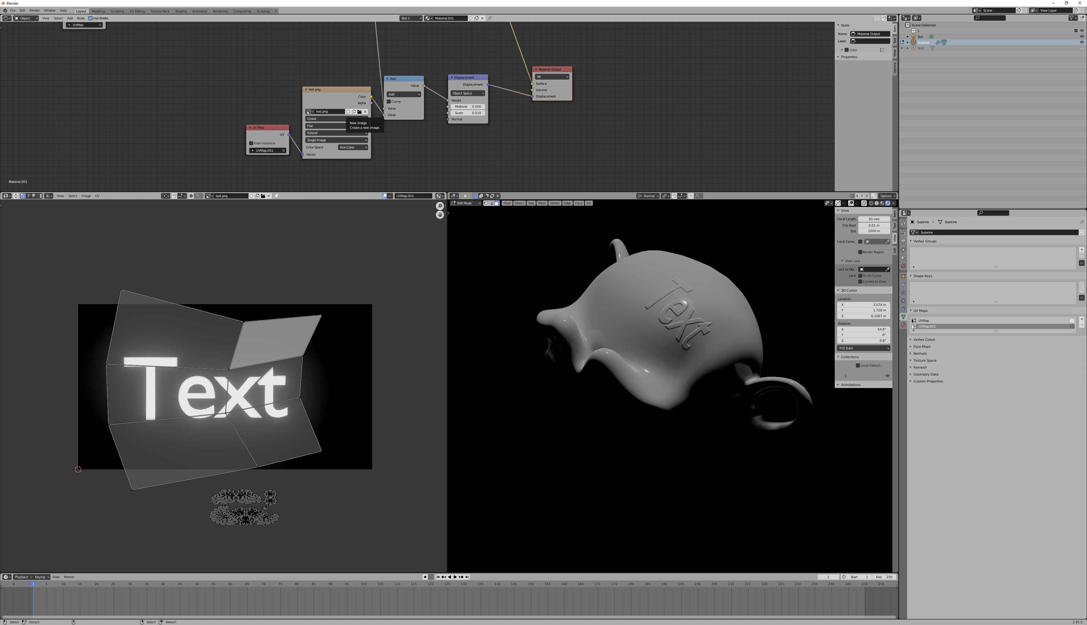
Usually, you’re going to be using the same normal for all of your shaders. (The easiest way to do this is to use a displacement node, with the material set to bump, rather than snake noodles to all your shaders’ normals.)
The exception to this is occasionally going to be clearcoat normals, which are present on Principled and Specular shaders, and every once in a while, represented by their own shader-- but in this case, your logo should affect clearcoat as well as anything else. In fact, if your material has existing bump for one set of materials and uses Principled clearcoat, without any specified clearcoat normal, you may want to create two sets of bump, one added together for most shaders, and one with only the logo for the clearcoats. (Again, this will be easiest with a displacement node, which will then set the default normals for both clearcoat inputs and bump inputs. That’s not quite the same as adding bumps, but it’ll be good enough.)
It doesn’t much matter that the logo is only over a small part of the mesh. Make a new UV map that only captures the affected part, and then use an image texture on “extend” border mode for the lookup. The most you might want to do is make a new submaterial, if you’re using the material elsewhere, in which case you might consider node grouping the main material to improve future editability (make it so you can edit the node group once, and affect all materials using that node group.)
Thanks for the suggestions so far guys! Such a steep curve to learn Blender… I was last doing 3d almost 20 years ago with 3DS 2.0… lol.
I think in those days what I would have done was some sort of alpha masking. Blender has some stencil functionality, and with texture paint, I thought that would be the way to go. But its a very confusing setup… I figured I could set up a texture (the engraved/burnt surface of the logo) then set up some sort of mask as a stencil, and simply paint it on to the area of the mesh I wanted. Including with bump…
You could texture paint the logo. But that’s a little more work-- you still have to do all the other stuff as well. It’s still a little bit better to texture paint the logo rather than just using the 2D original directly, as texture painting will compensate for any UV distortion that exists.
Explanations: if you already had something going into a displacement node, you can add your text before sending to displacement. Since you’re using a new UV map, make sure that any existing textures either specify the UV they’re to use, or set the original UV as the active UV (camera icon on UV maps in properties.)
I have otherwise hid the shaders, because unless things are really weird, it shouldn’t much matter exactly what is going into your surface output.
The texture is masked by virtue of being accessed in extend mode, which means that any values outside the 0,1 UV range use the closest border for their lookup-- a border which should be black, zero, no bump.
After nearly giving up, I deleted then created the exact same UV map (,001) and suddenly it worked. So now I have a displacement on the place it should be - THANKS!
Now I need to figure out how to make it a sub-material, not just a displacement…
Its a laser engraving, so it needs to be darker and rougher compared to the surface around it (in addition to being slight inset).
You can use the exact same image, on the exact same UV, as the fac for a mix shader node if you want. However, really, you need to study the material you’re using and get to the point where you understand it, so that you can edit its parameters for particular parts of your material.
I will keep trying! I am about a week into my blender career, so I cant expect too much… the node concept is pretty challenging for a very old school dude like me… thanks much for your help thus far!