Hey everyone!

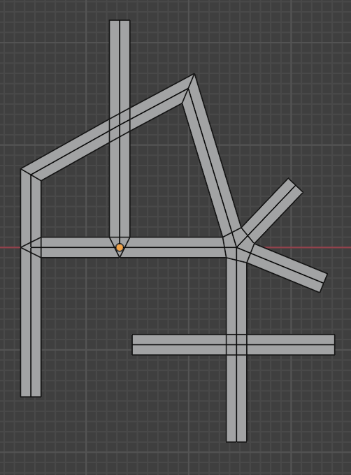
When working with edges in Geometry Nodes, certain problems bump into a limitation: edges don’t have a defined order around their shared vertices unless the mesh has faces. To solve that, I built a node group called Edge Corner Indices. This node computes, for each edge, four adjacency indices that tell you which edges come before and after it around each vertex, relative to some up vector (even if there are no faces). A picture might help to explain:
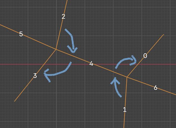
In this example, edge 4 connects the bottom-right vertex to the top-left one. At the bottom-right vertex (‘Vertex 1’), the next edge in rotational order is 0 and the previous is 1. At the other vertex (‘Vertex 2’), the next edge is 3 and the previous is 2 (all captured as edge domain attributes for edge 4). 5 and 6 are not considered neighbors of 4.
It’s basically face-corner connectivity without faces, and it enables some nice operations like filling holes, generating ribbons, or weaving patterns.
This is maybe the more interesting part:
How is that useful?
Example 1: Fill Holes
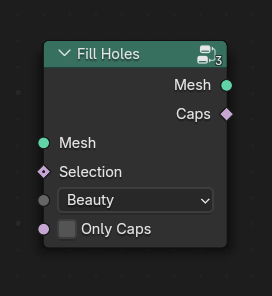
This does what the name implies, it fills all open boundary loops with faces.

The edge corner indices are necessary here to disambiguate cases where boundary loops meet in a single vertex.
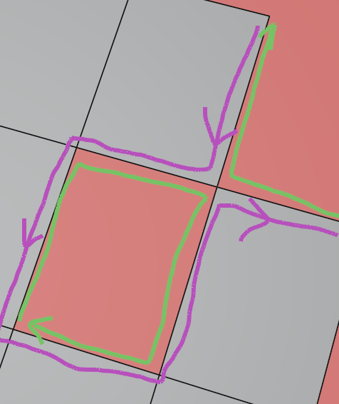
In this example it would be hard to tell which loops should be connected for the shared vertex, because the connectivity information of the corners is absent until those very corners are created. We can easily tell that the green loops are the correct solution here if we have corner indices.
On its own Fill Holes seems like an essential modeling tool and is hopefully useful to someone!
Example 2: Outline Edges
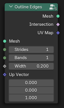
This will create bands/ribbons for each input edge that have constant thickness and are connected with proper geometry at the intersection points. This could for example be used to create road networks just from edge connectivity while generating nice intersections.
Note that the up vector does not have to be constant over the mesh. If we use the normal vector of a mesh surface, we get “wireframe” ribbons along the edges. If we fill the holes between these wireframe ribbons with Fill Holes we get a very rudimentary bevel in geometry nodes:

Example 3: Edges to Knot
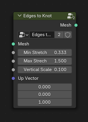
This is inspired by a houdini setup built by everythingcg. Unfortunately the original website seems to be down, but there is a video post on reddit and wayback machine has a copy with a good explanation.
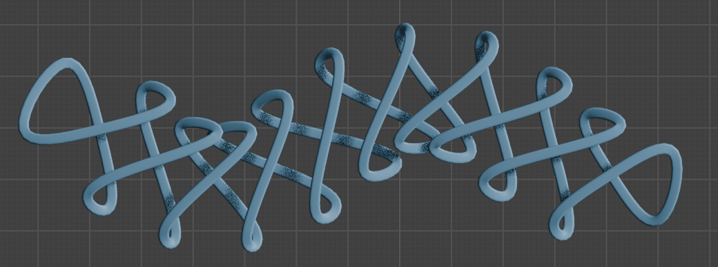
This uses the calculated edge connectivity to generate a weave around the edges:

This can generate nice patterns, some more examples:
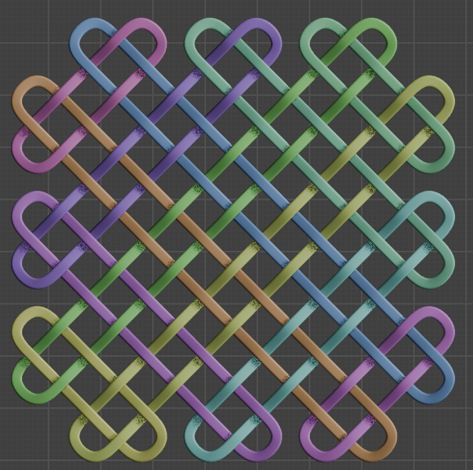
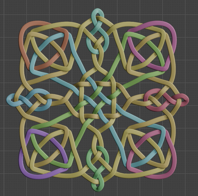
(Colored by island index)
Edge Corner Indices
This node, together with the examples can be downloaded here!
edge-corner-indices-examples.blend (288.9 KB)
Hope that helps!