I am new to Blender and have been using it only for a week but have been making good progress. I’m mostly interested in using it to develop files for 3D printing. One issue I have been having is as follows. For example, if I start off with a cube that is 10cm x 10cm x 10cm, how do I create a new edge 2cm in from one of the sides? In SketchUp I used the ruler to slide along an edge to create a specific point so that I could draw another edge from it. I have tried selecting a vertex and extruding along an edge while constraining to the appropriate axis so that I would have a vertex to snap to later but I have a hunch this may not be a good way of creating my model as I am basically creating edges over the top of other edges.
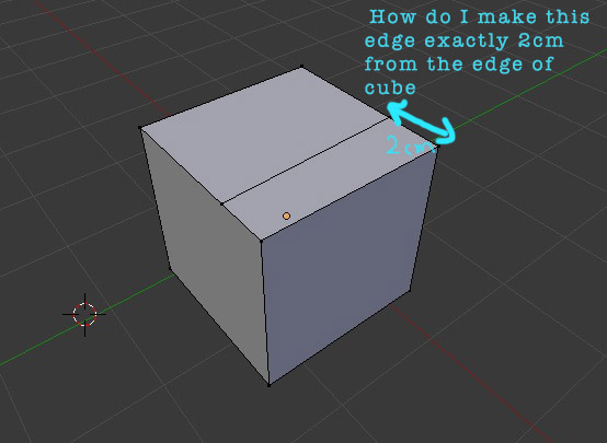
I have attached an image to give a better idea of what I mean. Hopefully this makes sense and someone can point me in an appropriate direction.
In edit mode the N properties panel will tell you the coordinates and mean coordinates of vertices and edges/faces. The numerical input lets you reposition already created geometry with absolute precision.
However you must be in a metric scene to use cm.
In edit mode, hover the mouse pointer over the edge where you want to create a new edge, press CTRL-R, a purple preview loop cut will show up where an actual loop cut will be created when you left mouse click. You can now slide the position approximately where you want it and click the right mouse button to confirm. It is possible to “edge slide” the entire loop cut or select and move individual vertices.
You could select the edge you want to subdivide and then press W. The faces might now have more than 4 sides, but you can select vertices and use J to connect them and simultaneously cut the face they share.
Another way would be to simply start with a square face (add->mesh->plane), press E for extrude, press 2 for the distance it will move the new face (and constrain the movement to, say the z axis by pressing the Z key until you see a line through the object parallel to the z axis). Left mouse click confirm. Press E again and now extrude 8 units. There are more ways to achieve what you are looking for, but these should give you a start.
Avoid making cuts like that on your models. You’re creating faces with more than 4 sides, which is generally a bad idea unless it’s on a perfectly planar area of a non-deforming mesh.
Thank you for all of your responses. I have had some success with the properties panel and the other suggestions people have made although it doesn’t quite represent the simplicity I am after. I have attached another example to show what I mean. I have created a cylinder. If I select all the top vertices and use the extrude tool I can easily extrude up along the Z axes above the cylinder by typing -2cm without any problems. If I extrude down along the cylinder I can do similar by typing 2cm. The only problem is that there is now a face sitting underneath the newly created face from extruding. The last screenshot attached shows how the orange edge lines do not follow the face correctly when selecting the faces below the newly created edge. Hope this makes sense. Cheers.
Well extrude is the wrong tool if you just want another loop parallel to and below the top, i.e. without the interior face. Easiest is going to be to CTRL R to add an edge loop, position it exactly at the top and then GG Z 2 to slide it in the z axis 2 units