Add a LUT to Color Management Setting

I need to load my LUT internally in Blender. As far as I’m aware there is no option to load LUTs in Blender. But there are Color Management settings in Blender files.

…\datafiles\colormanagement\

What do I need to change in config.ocio to make it possible to choose my LUT in blender?

I see that the files in lut folder are in .spi1d, .spimtx formats. I have .cube LUT. Do I need to convert it somehow?

Please help me to figure this out. Thank you.

1 Like

Okay, I figure out how to edit config.ocio to add more profiles.

Does anyone know how to covert .cube to .spi3d?

Nevermind. I figured out how to load my LUTs to Blender.

1 Like

Care to share how so others can benefit too?

I did it in a bruteforce way. You need to edit config.ocio and make some folder.

Go here:

…\blender\2.81\datafiles\colormanagement\

Make a new folder external here. Upload you LUTs in the folder. It’s better to use short names for the LUTs and no spaces.

The list of supported LUTs is here: https://opencolorio.org/FAQ.html

Before making any edits to the config.ocio make a backup of it.

Add your new folder with LUTs to the search path:

search_path: "luts:filmic:external"

Now you create your veiws. Find these strings:

displays:
  sRGB:

Now you add there your new LUT like this:

    - !<View> {name: My LUT, colorspace: My LUT}

Find this:

colorspaces:

This is where you define LUTs.

I just copied already existing block:

  - !<ColorSpace>
    name: False Color
    family: display
    equalitygroup:
    bitdepth: 32f
    description: |
      Filmic false color view transform
    isdata: false
    allocation: lg2
    allocationvars: [-12.473931188, 12.526068812]
    from_reference: !<GroupTransform>
        children:
            - !<ColorSpaceTransform> {src: Linear, dst: Filmic Log}
            - !<FileTransform> {src: filmic_false_color.spi3d, interpolation: best}

And changed these parts:

    name: My LUT

    from_reference: !<GroupTransform>
        children:
            - !<ColorSpaceTransform> {src: Linear, dst: Filmic Log}
            - !<FileTransform> {src: my_lut.cube, interpolation: best}

This way you’ll be able to change View Transform in Color Management to your LUT.

Make sure you follow indentations strictly when changing the code. Otherwise it won’t work.

Unfortunately it’s not a complete solution yet since there is a transformation happening between spaces and I don’t yet know how to control it with values in these parameters.

Reading OpenColorIO at the moment.

7 Likes

It’s probably wise to define aesthetic LUTs as a Look, not a View.

If you have questions, I might be able to help, but require more context.

It’s good @troy_s. I figured out how to control and transform color spaces. Had to really dig in in OpenColorIO docs though :slight_smile:.

Funny thing. I tried to find your contacts on BlenderArtists but couldn’t. Thanks for offering though. I might need some help with some specific question to fully understand OpenColorIO. I’ll write you a PM when I do.

Thanks again.

A word about Looks…

Set the process space to the transform you require the data state to be in. For example, for a CDL that you have designed in Blender via the CDL node in the compositor, the process space would need to set to linear to be a 1:1 match.

If you have developed something outside, you’ll need to take the process space to the context you designed the LUTs under, such as a shaper or other needed pre-transform for a 3D LUT.

Thank you. I’ll keep that in mind.

Did you find out anything else about adding .cube LUTs inside blender?
I followed your guide and managed to get LUT inside, but it doesn’t look like it gives proper color management.
It has lowered contrast and it is somewhat brighter than it should be.
So I guess the settings are wrong…

I did but it was rather hacky. I figured out how to add custom entries to color management system. But doing proper color space conversion is over my head. I kind of got good workflow but is an approximation of what I wanted. Still it works for me but there is a lot of BUTS, because I finish images in Photoshop and it’s also pretty weak software for proper color managed pipeline.

Fortunately for me my projects allow a lot of creative freedom so despite pretty broken workflow color wise I can get great results anyway.

Right now I am eagerly waiting for Cycles spectral branch to be finished and merged. It should help ease a lot of color management issues since hopefully it will be properly color managed. Maybe even will have an option to side load LUTs.

I tested, but in the end original Filmic looked better.

Cycles spectrum branch? You have any links?

If you are keen about building a custom look library, my best advice is as follows. Bear in mind that all looks / 3D LUTs are based on a known input and known output. For the sake of discussion, I’ll assume you are using Blender “as is” with Filmic as the display rendering transform gamut map.

  1. Open the compositor.
  2. Add a CDL colour balance node. Make sure to set to CDL and not the default Lift Gamma Gain, as the Lift Gamma Gain approach has no place in a scene referred environment and breaks things!
  3. Route your particular image flavour to the CDL node, and adjust the CLD Slope, Offset, and Power to meet your needs.
  4. Record the values.
  5. Add the values as a CDL Look entry in the OpenColorIO configuration.

The format of the Look will appear as this:

    name: Test Library Look
    process_space: Linear
    transform: !<GroupTransform>
        children:
            - !<CDLTransform> {slope: [1.2, 1.2, 1.2], offset: [0.2, 0.2, 0.2], power: [1.2, 1.1, 1]}

Make sure you backup and save your default configuration just in case you make a mistake. No harm done, just revert and try again. Also note that YAML is ridiculously fussy with whitespace, so make sure your text editor isn’t stuffing things in that cause problems!

It should be that simple.

The Slope, Offset, and Power are worth examining a bit here. That is, when operating on radiometric-like linear values, the following applies when thinking about the input along x versus the output along y on a generic plot. I’d encourage everyone to drill into the following three concepts to really get a handle on grading your work.

Slope

Slope is multiplication. That is, it is exposure when applied to radiometric-like linear data. If you were to want to decrease exposure by two and a third stops, the slope value would be 2^-2.33.

Power

When applied to radiometric-like linear data, power is a collapsing of values toward and away from 1.0, which is a rather arbitrary math value. This loosely is contrast, with the caveats outlined below.

Offset

This is a simple addition or subtraction. The net sum is that on radiometric-like data it will have a tremendous impact on the lower values, while on the higher values it will essentially become non-existent. It is the least useful of the controls for generalized grading, unless the desire is to lift up darker radiometric-like values uniformly. Be extremely careful using this when starting out, as it will typically overcomplicate typical grading needs.

Nuances

It should be noted that by default, due to the way that math works, that a power exponent function will collapse values toward or push values away from 1.0. In a radiometric-like linear value range of a render, 1.0 means absolutely nothing, and is simply yet-another emission level.

When grading, it is common to want to adjust contrast about a pivot point. That is, it might be desirable to have a specific value remain at the precise value, and collapse values toward or away from it. This is known as a pivoted contrast, and is more or less easy to accomplish using three CDL nodes for clarity.

  1. A CDL node that adjust the exposure such that the pivot point ends up at the math magic spot of 1.0.
  2. A CDL node that adjusts the contrast using the Power value.
  3. A CDL node that returns the exposure to where it started, putting the pivot back to where it began life.

As an example, if we were to attempt to adjust contrast around middle grey of 0.18, the following would apply:

  1. Set a CDL node with a Slope value of 1.0 / 0.18
  2. Append a CDL node with the Power being the contrast desired.
  3. Append a CDL node with the Slope set to 0.18 to scale the values back to the proper positions.

This now is a real-time pivoted contrast, which can have a Value node routed to the contrast value and pivot points as needed.

Finally, you could convert the three into a look for your look library, by integrating the values you arrive at using a Look as outlined above.

Hope this helps.

3 Likes

This is really useful and interesting information. Thank you.

So if I understand it correctly, if we have 3 CDL nodes, OCIO configuration would look like this?

name: Test Library Look
    process_space: Linear
    transform: !<GroupTransform>
        children:
            - !<CDLTransform> {slope: [1.2, 1.2, 1.2], offset: [0.2, 0.2, 0.2], power: [1.2, 1.1, 1]}
            - !<CDLTransform> {slope: [1.2, 1.2, 1.2], offset: [0.2, 0.2, 0.2], power: [1.2, 1.1, 1]}
            - !<CDLTransform> {slope: [1.2, 1.2, 1.2], offset: [0.2, 0.2, 0.2], power: [1.2, 1.1, 1]}

Where every line would have corresponding values?

Btw. what about using LUT presets? You said that we need the information about process space.
Can this info be extrapolated from the LUT so we can obtain correct transformation?

Yes. You can also add in the other types of transforms as required. Note that it is worth examining how the CDL is calculated, as you can concatenate a couple operations in some cases. Also note that you can store the looks into external CDL files of various types.

Indeed. A LUT of any sort is nothing more than a baked formula, and the assumptions of input and output are baked into it. Plenty of them are random garbage. The remaining that are not require acute attention to the encoding of data for the input to the LUT, and the encoded state for output.

A simple example is the ARRI Alexa REC.709 LUT. It expects exactly one form of input (ARRI Wide Gamut with LogC) and transforms to one specific output (BT.709 with BT.1886 reference display).

In the vast majority of the cases, no. Typically, if such information is unknown, the LUT is hopeless junk anyways. In fact, it is a terrific way to identify junk from not-junk; if the colourimetric information is provided, the creator knew what they were doing. If it isn’t, the creator is likely clueless.

2 Likes

I have some Print Film Emulation Luts from Juan Melara, they need LOG-C as in input and REC.709 aus output. How do i set up Blender to use them correctly?

You could try the following modifications to the config.ocio file:

  1. Add this stanza to the configuration.
  2. Copy the 3D LUT to the appropriate LUT directory.
  3. Make a new look slot by duplicating one of the existing looks and renaming it to the LUT name you desire.
  4. Set the process_space to the encoding added above Alexa Wide Gamut LogC.
  5. Change the name of the file in the FileTransform look duplicated from above in step 3. to the name of the LUT in 2.

That’s the general idea, plus or minus some potential discrepancies on the GPU front. You might want to use the configuration I made way back from GitHub as it is significantly cleaner and clearer to understand. Hope this helps.

1 Like

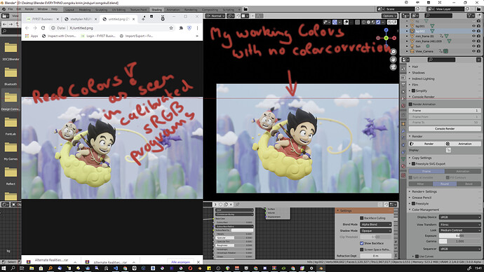
heck yeah guys i finally managed to create a correction profile for my tablet monitor(huion camvas 22 plus) , its a wide gamut monitor and therefor would be way saturated in the blender viewport and blue shifted into cyan.

and now corrected

like you see here my working colors are my target, and i would work in wrong colors all the time without the correction , like i already did here , its way to dull , but my working colors looked really nice in comparison.

its not 100% the same (but its also not 100% the same in krita, photoshop, and chrome either ) , it hits that 95% target though , its slightly darker but enough to confidently choose my colors on this monitor

2 Likes

I finally added custom LUT into Blender CM.
But as I am still totally lost as far as color transformation goes I cannot guarantee it is correctly implemented.

Here is what I did.

  1. Copy .cube file into \colormanagement\looks folder.

Btw. first I though I can’t use .cube LUT in Blender, so I wanted to convert it to .spi3d. As I couldn’t find out-of-the-box converter .cube → .spi3d I decided to open it up and see how readable it is. It was easy to figure out how to copy values to corresponding places and just saved it as custom.spi3d

  1. Here is what I changed in config.ocio file:

I added

- !<View> {name: customLUT, colorspace: customLUT}

in the

displays: 
   sRGB:

section.

And then I added

- !<ColorSpace>
  name: CustomLUT
  family:
  equalitygroup:
  bitdepth: 8ui
  description: |
    Custom Description
  isdata: false
  allocation: uniform
  from_reference: !<GroupTransform>
    children:
      - !<ColorSpaceTransform> {src: Linear, dst: Filmic Log Encoding}
      - !<FileTransform> {src: custom.cube, interpolation: best}

in the colorspaces: section. It is very important to paste with exact indents, otherwise it won’t work. Of course “custom.cube” should be changed to name of the LUT file you are using.

It definitely has same color correction, but I’m not sure if it should be applied like this to scene referred data or not. Contrast is pretty strong.

First I followed this guide but I couldn’t figure out where does Base_DesatCrosstalk_DesatLog.spi3d and DesatLog_to_EncodeLog.spi1d come from. So I just went and applied it like example for Retro Film i found online.