Adding a normal map to a Blended Box Mapping (Triplanar) Cycles node setup (no UVs)

(TL;DR How do you set up UV less Normal maps?)

I have been working on a Cycles node setup using the Blended Box mapping technique, but I cannot work out how to properly set a normal map this way.

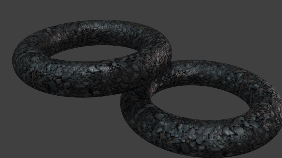
For those who do not know how this works (I would say most have not heard of it), Blended Box Mapping is a way of projecting textures onto an object from the X,Y & Z planes and blending the edges of where those images meet. This is great for more natural organic textures, where the you do not want to UV unwrap objects (for speed, workflow purposes, procedural generation, or parametric techniques).

I am using the node setup from Tears of Steel as a starting point:
https://mango.blender.org/production/blended_box/

To show what happens when this is done, see this video:

I have also seen this referred to as Triplanar mapping. Although I am not sure if there is any distinction between the two, but the example I have seen does have a different node setup. Here is a node setup under that title:

What I have created is a way to add leather textures etc to clothing, accessories etc. I can use this to separate the texturing process from the assets. Once the material shader is complete, I can use it to render out newly created items quite quickly, without having to UV unwrap multiple, complex shapes. This is about speed and efficiency.

To further improve the speed that this renders I have also thrown in a matcap node setup just for lighting reflections.

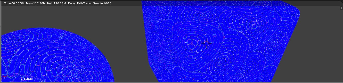
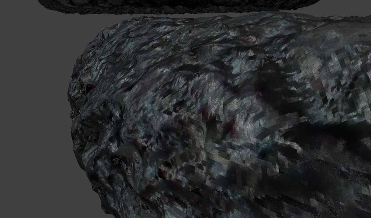
Everything works as it should but I cannot work out how to connect and use the Normal maps I have created in Bitmap2Material. I may or may not have stumbled across the solution, only to loose it again, so here I am.

Anybody know how to setup Normal maps without UVs in this case?
Looking forward to your input.
Chris Lee

This sort of worked, sort of…


The normals aren’t reflecting the “smoothness” of the smooth shading that I have applied to both these surfaces. So it’s reflecting the “True Normal” rather than the… other kind of Normal.

The Vector Math node set to Average seems to be an important part of the equation. Maybe a hack, but without it you get this:


Whereas with the node in there, you get this:


And, by the way, you don’t have to use the old technique from ToS; now it’s an option with image textures in the Node Editor, as you can see in my Node Setup.

Great! Thank you for your help Benu. I have tried that out and it seems to work. It took me a few minutes to work out the average node was a vector math node, but I got there. ;D
I will wait to see if anyone else has further suggestions before marking this as solved.

How did you know about the Image Textures node getting the blended box mapping option. Was this info posted somewhere? Can you reference it? I’m just curious about the development and have found little reference to it.

I actually made that video you linked to in the first post. The concept of blended box mapping is brilliant – simple but very effective. So I’ve had my eyes on that feature for years; I think I first noticed it here: http://wiki.blender.org/index.php/Dev:Ref/Release_Notes/2.64/Cycles

I thought your video was great Benu. It very clearly demonstrates the feature.
So why is this normal mapping solution different, and sort of works? I am not clear on that.

Hi Benu, when we discussed this previously, I had used your setup but later found that the surface normals looked strange from the back. I assumed this was because of the method you used being a hack, that may not be perfect.
I just revisited this and wanted to demonstrate why the default normal map did not work with blended box mapping. I created a test scene and set up one torus with a bump map blended box mapping node setup and another that had a normal map instead. However it seemed to work. At least to the point where I am now not sure what the issue was I had when I posted this. Did this get fixed in a recent version of Blender?
As you are the only person who has tried this, can you give it a go without any sort of hack?

The top torus has a bump map and the bottom torus has a normal map.


I am uploading my blend file with packed textures to Dropbox for you to have a look.

Hi infin8eye, I was surprised to see this old thread brought back to life! If we just compare the output normals, the lower torus’ texture is larger than the upper torus:


When I compare what’s generating the bump maps, they seem to align with the original image. I think the main difference is how Blender generates a bump map from an image, and how your third-party app is doing it.

For instance, if I turn on the experimental features, enable displacement mapping for the toruses, and run the NORMAL output into the displacement attribute (which, I believe, is not the best technique, but it helps for the demonstration here) I get this with the top torus:


While I get this with the bottom torus:


(This isn’t the same part of the texture, by the way.) Notice how different the dithering patterns are. The top torus has a more regular dither, distributed across the entire thing, which serves to smooth out the texture. The bottom texture is less regular and, to my eyes, more effective:


IN SUM: The difference here is due to the fact that you’re using two different apps to generate the normals, and they do it differently. You probably won’t be able to make them match exactly, but they are accurate in their own way.

(Oh, and of course, that wasn’t your question, which I think was to verify that whatever this issue was, it’s gone now. Yes! It’s gone!)

Thank you for your analysis. This issue had bugged me at the time and I stuck with bitmaps (which are still surprisingly good in Blender), but I brought it up in a chat with someone and tried to reproduce it. I appreciate you putting some time in to have a look at it again.

Yes it makes sense that the results differ due to the normal map generation. I know from using Bitmap2Material, that the results can vary a lot depending on the settings you choose. With this example I chose to use some pre generated maps from Cubebrush for the test (to eliminate variables).
https://cubebrush.co/pgmsource/products/xefhvq

When I created these toruses using blended box mapping, I fiddled with the nodes and got a reasonably good result. This surprised me so I got back on here to discuss. I am glad I did as your observations are worth noting for the future.

I am really glad to see that the issue, that prevented the normal maps from working properly, has been resolved. As most people do not even know about this technique, it is impressive that they still sought to resolve the issue. Another win for Blender fixing bugs ten times faster than commercial software.