I’ve been following a tutorial recently, and am a little confused at a certain step involving extruding a region from a circular section of the model, and adjusting the resulting extension. The tutorial calls for moving the extension by the extruded faces to have it at an angle, then adjusting the faces from there, tweaking the vertices, scaling them appropriately, and so on. Angling the extension that way deforms it slightly, but the main problem I have is lining up the faces with the angled extension. Is there a better way to do it than by moving their vertices into place or rotating the faces manually? Is there a better way to rotate extruded regions than by moving their faces around? Any further tasks, like scaling the faces, will distort the extension unless I have its faces at the proper angle. I will also add that I need to line up the faces while keeping their uneven sizes.
Edit: I may have not been coherent enough, so let me know if any clarification is needed.
Perhaps you need to use Shear to ‘rotate’ the extruded mesh.
You can also set the Transform Pivot Point to Active so the mesh rotates around the Active vertex.
You may need to add a custom Transform Orientation so you have the XYZ Axes aligned to the faces you are working with…
Screenshots are needed to totally understand your issue. Make a simplified version of the problem to use for the screenshots if that will make it easier to help us to understand.
Or, if it is not a paid tutorial, share a link and the time.
My problem with this step (Step 31), is precisely angling the faces to be a similar angle as the extension (the horizontal stabilizer), along with straightening the faces. I could try to move the vertices into place following the tutorial, but it would be a rough and tedious process. Making the wings involves a similar process, with some minor differences.
Step 47. It’s a slightly unrelated problem to the question, but as these are cylindrical faces being extended, there’s the issue that, besides the aforementioned problem of straightening the faces, any loop cuts or similar will result in angled faces that are harder to work with and will need to be straightened as seen in this step. I’m thinking of straightening the faces on the cylinder first before extruding them, but that distorts other faces on the cylinder and ruins its overall shape, unless loop cuts are made. Exactly how many cuts are needed, I’m not sure, and these cuts will increase face count, which I’m trying to keep to a minimum. Admittedly, I am working with a slightly different plane, and am thinking of shaping the faces to make the wing look aerodynamic (the tutorial just has the rectangular-looking faces extended and scaled as is), as I’ve seen other low-poly models featuring slightly curved wings without much distortion of the main cylinder.
If you are using 2.79, mention that first… saves everyone from giving 4.0+ instructions that are no use to you.
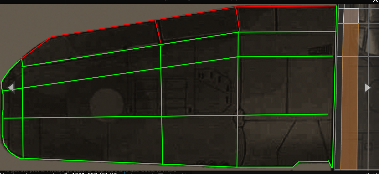
For starters - dont be super fixated over accuracy. The lines in the blueprint are several cm’s thick, so you should focus more on getting it done, and come back for a tweaking session in a couple of months once you know more. This is a common art thing, ‘I cant do what that expert with 20 years experience did after my 2 days practice, so I give up’… Getting to the end is far far more important than accuracy.
Do you have blueprints set up for the front view??? Set up the 3 views available in the Blueprint - front, top, side. Each view needs its own (copy of the) image aligned to the correct location.
Oh - accept that the different views will not match properly. You often have to pick one to use as the basis and tweak the others as you work.
29-32. Extrude then scale to zero on x (s, x, 0) to make it all ‘square’ and the top and bottom aligned. Then drag out to the tip and align / scale. Remember you can place the end so the middle is correct the use s, y to scale the front/back inward - rather than select, move repeatedly.
Expect to be moving the loops that run around the planes body. gg (pressing g twice) is edge slide mode, so as you move the loop it adapts to the size change along the length of the body. After placing the tips you will want to adjust the base as well. “rough and tedious process” is what many call a standard day. Lol.
Again extrude then immediately scale to zero on X. And remember to extrude along X, not just out along the face normals like in the tutorial. So e, x … to whatever length. If you know the wing length you can type e, x, 2000 (for example).
That loop cut near the wing base. Use the knife tool instead. K to activate. At either the top or bottom of the 3D view are a bunch of letters for extra things to activate. You can press one to cut all the way through, and another to cut limited to angles. Press the buttons to use them (c & z in old versions?). Click just out side the wing on one side, then on the other and press Space or Enter to finish. Hopefully that gives a edge loop with the tops and bottoms nicely matched. GG to slide the loop if needed. It can help to drop in a knife cut at either end so its easier to work with all the middle area - no angles between top and bottom, or other irritations.
Also consider doing a small extrude with the x to 0 scale. And align that first extrude to the area where that loop is placed. Adjust to fit, then extrude out to the tip. Some people prefer to box model the outline and add loop cuts, some prefer to extrude, adjust, extrude, adjust. Dont stick with the one you dislike because it was in the first tutorial you followed.
Got the loop tools add-on activated in the Preferences? You need it. If you have tweaked the wing (or anything) and parts are out of alignment the Loop Tools > Curve option will realign the edge to two endpoints…
If you select 3 or more points and click Curve it makes a curve.
Bridge Loft and Space are also highly useful parts of Loop Tools. Watch some tuts.
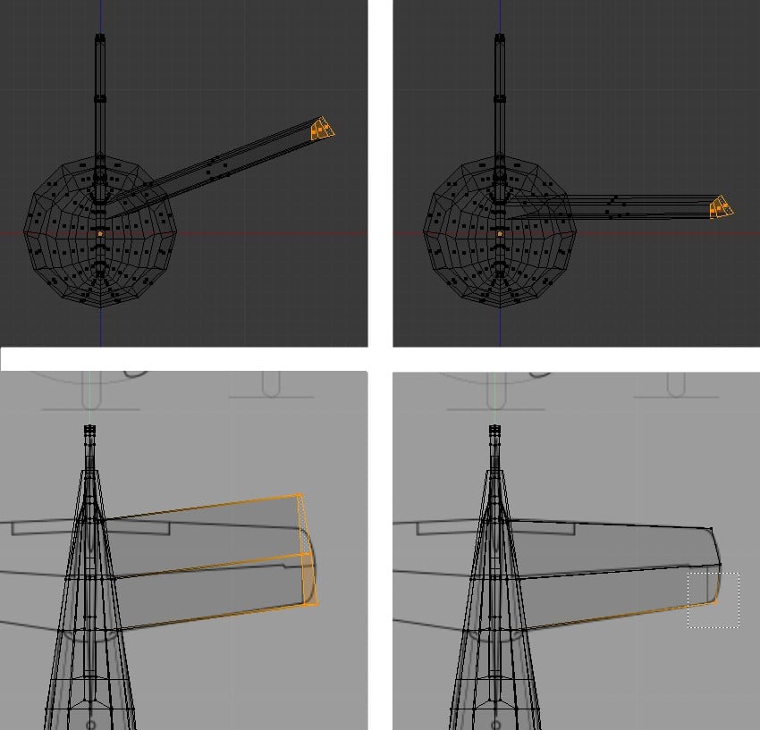
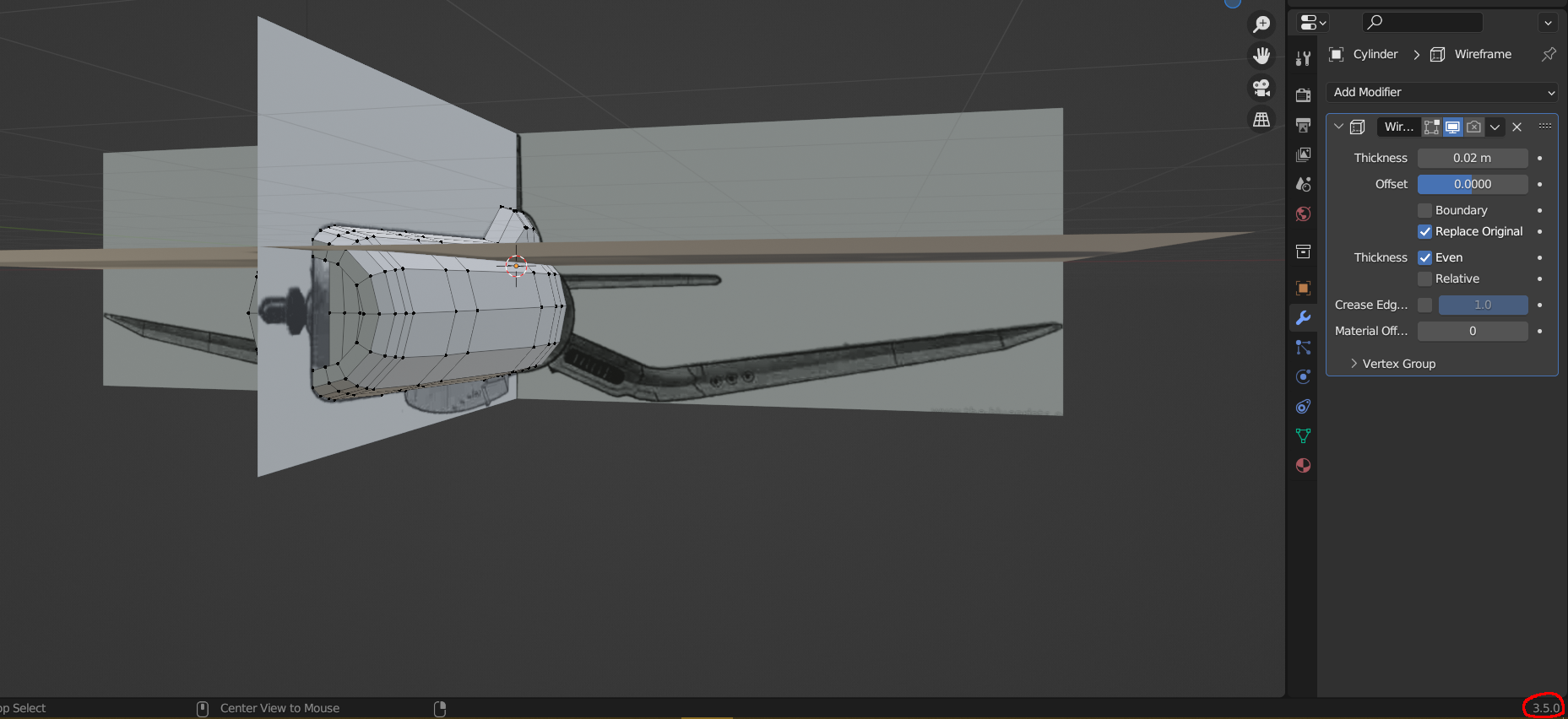
Not to drag this discussion on for too long, but I suppose this situation calls for showing what exactly I’m attempting to make, and the Blender I’m using to make it (probably should have stated what Blender version I’m using earlier given how old the tutorial is). My setup might be a little awkward, though I’m not sure.
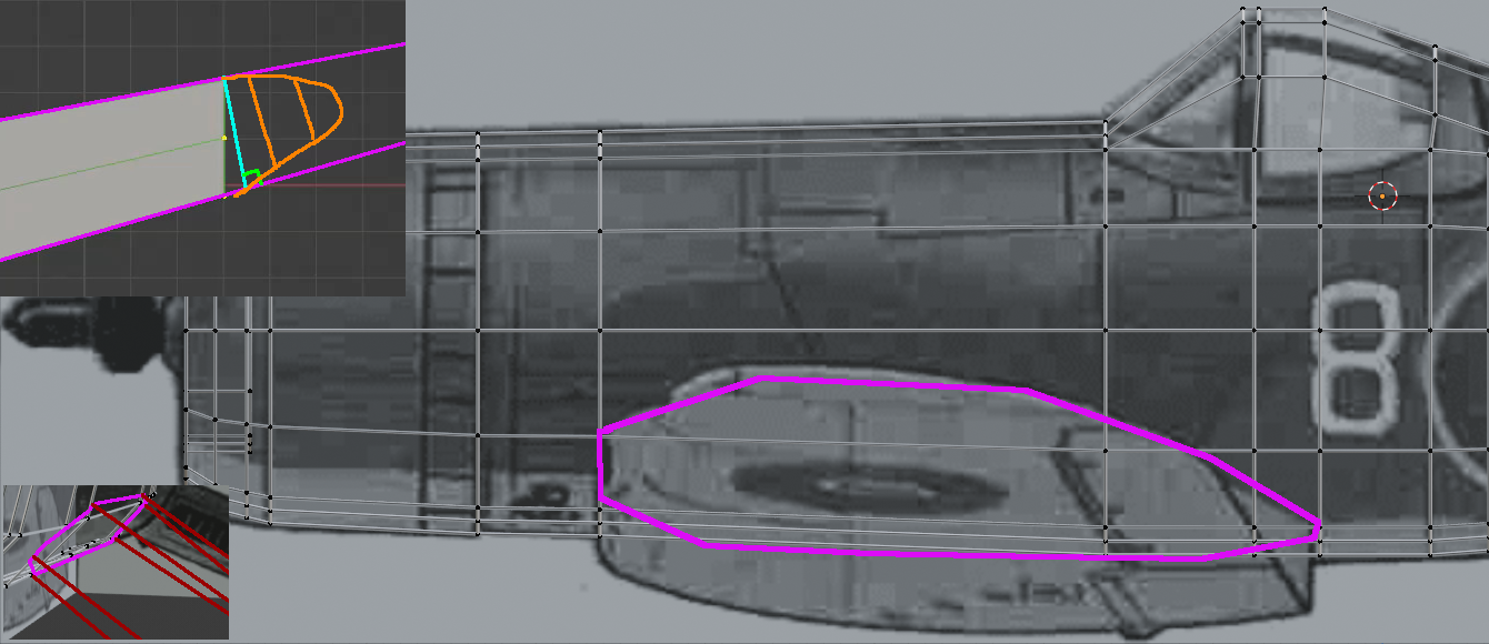
I’m thinking of attempting to get the wing in that shape to better match the wing’s aerodynamic shape, and to match the slight detail elsewhere in the plane, like the nose and the very rear of the plane. I was intent on making the faces on the extruded region straight so I could simply extrude further without distortion until I completed the wing’s tip, as I have similarly done for the main body’s rear.
Here’s another screenshot, yet another view of the blueprint, and what I am aiming to model.
Edit: Perhaps I should have chosen a simpler plane to model, but well, the Corsair is one of my favourite designs from that period. I’ll take your advice on watching some tutorials, if only because I don’t really know what I’m doing anymore, though I’ve never had much luck with finding tutorials relevant to my skill level or issues.
To get the profile I would go back to loop tools and use Circle to make the tip into a circle, then use proportional editing to pull the rear into a point.
Or do this just after extruding from the fuselage.
It will help to make the wing separate from the body, so you can add edge loops without worrying about the loops running over the fuselage. Although it may pay to start it from the fuselage then duplicate/detach it to build it.
Do remember a lot of the wing detail can be texture so you only need a basic form. Yes, I have not allowed for the shape from the front view…
The flaps are given an inset or a bevel to make the extra edge around them and are then separated by selecting and pressing Y.
The front edge gets bevels on two loops to make the nice curve.
Along the front edge the big notch and the gun barrel holes can get added by using a boolean (modifier) to cut out those shapes with cylinders and an edited cube.
That tip of the wing sketch with the right angle - use (Mesh Menu > Transform >) Shear to get it all to 90 deg. You need to press an axis key to give the tool a direction to work in, so it may seem to do nothing until you give it the axis. Once activated move the Mouse left/right to set the shear amount.
Loop Tools > Flatten can help in similar situations.
Do you have this tool set to Tweak?
The Tools with the tiny triangle in the bottom right of the icon have other modes - click hold and move over an option then release.
Tweak means no more select then press move. Just click and drag. It makes adjusting things so so so much easier and faster. Remember to NOT use it on curved surfaces…
You do not have to find Airplane modeling tutorials to learn how to make airplanes. All modeling is the same thing in different shapes. Zerobio is a good channel. Slow/real time and no loud music. Check his beginners tutorials. John Dickinson is another good to learn from channel. Check his ongoing topology playlist. Topology understanding is the basis of everything in 3D. He is building a motorbike in 3D. Every single part. So there are lots of videos to watch.
Dont worry about asking lots of questions. Once we drag you over the first big hurdles you will be away…
I took quite a while, so if you’re still there, I’ve followed at least some of your tips, and the tutorial’s in regards to leaving the wing squarish and use textures to try and make it somewhat aerodynamic, a decision that has been hard to stomach—the plane looks weird and ugly as is. I have refused to separate the wing as the idea of a model inside another sounds messy, and I’ve seen cheap looking models that have such components separate and jutting out.
Unfortunately, my question still hasn’t been answered. I need the wing’s tip to somehow snap into a perfectly precise 90 degree angle, as if there were imaginary lines extending from the wing, like in my earlier diagram concerning this. The shear tool seems to be no different from the rotate tool in this regard. Could it be that I’m not using it right? None of the additional commands, such as the one for “precision mode”, appear to be working as I’m shearing. I do have that other tool set to Tweak, and have likely had it on that setting this entire time. Loop tools produces crazy results, like massive circles, and it seems as if I can hardly use it properly.
As for tutorials, I generally prefer written ones, as yes, YouTube tutorials can be obnoxious and hard to follow, though my main issue with video tutorials is that I am generally conservative regarding my internet data. However, that’s less of an issue these days, and I am open to checking both your recommendations, and oo_1942’s, out. I will definitely have to if I want to continue with 3D modelling, because my plane looks hideous for my own personal, subjective tastes.
Select a face and press Shift-Numpad 7 (or Shift-Numpad 1 or Shift-Numpad 3). This aligns the view with that face. So what happens if you drag the wing tip out too long, align to one of the faces and do a knife cut? Theoretically you have a 90 deg squared cut. Delete beyond there and fill.
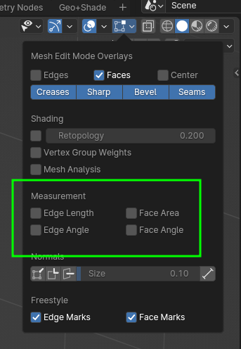
Do you use the Measurement Overlays??
I know what that is like. I used to have to go to the local library for free internet and download tutorials with my laptop. Of course not every country has that.
Happy blending. I am off to curl up with a book for a while…
Don’t remove important context when quoting my post, please. I need the faces to be straight at a specific angle, so to speak. Straight relative to the extension, the wing, which is itself at an angle, while the faces are straight, relative to the “world” instead. And damn, that was an embarrassing grammatical error on my part…
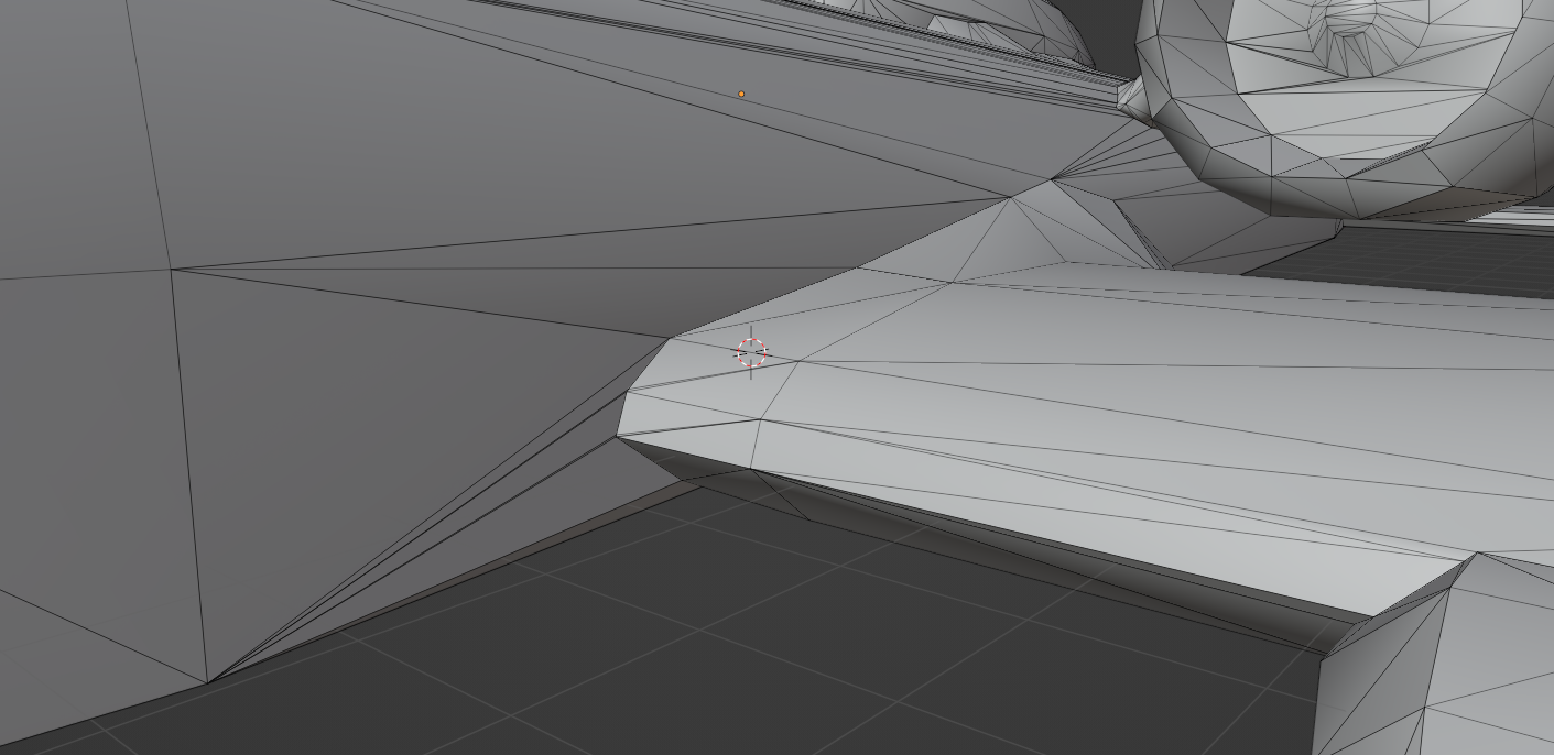
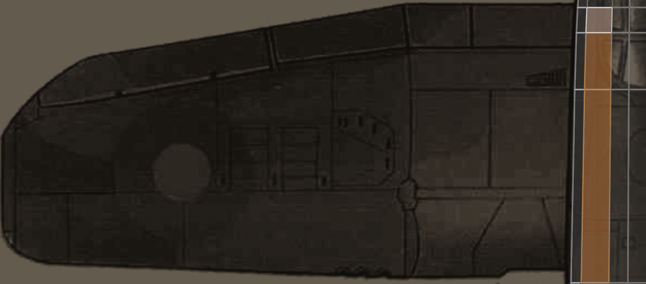
If you do return later, I have a final modelling related question. How would you edit the faces on an object, say a cylinder, to make, for example, a wing-like shape, like in my rough diagram, while preserving the overall shape? The first thing that came to mind was some tool that would ‘generate loopcuts’ to maintain the shape of the object while editing, though I don’t know much about modelling, so I’m not sure if it even works that way.
Something similar to this, but somewhat tidier, quads only? (It’s the most immediate example I have on hand)
That sounds like Lofting. Which means take a profile shape and duplicate it with scaling and adjusting to give the wanted (changing) shape of the wing. And then filling automatically between those shapes. This idea is often used in plane and ship modeling. Loop Tools has a Loft option.
It is usual to make the shape with a Bezier Curve, so it is easy to adjust the shape, and then convert the curves to mesh (Object Menu >Convert >Mesh) to do the Lofting.
Look for blueprints of your model that show the loops of the actual struts (or whatever they are called) and add loops at every strut. Then Loft. It makes it so much easier. You may need to go for toy plane model designs to get the strut locations. Yes that is a serious suggestion.


")