Yes, it should be possible. I don’t have any experience with it, though, and I’d need to see a mesh (w/ UV map) and sample flow map in order to check myself before I wreck myself (which happens.)
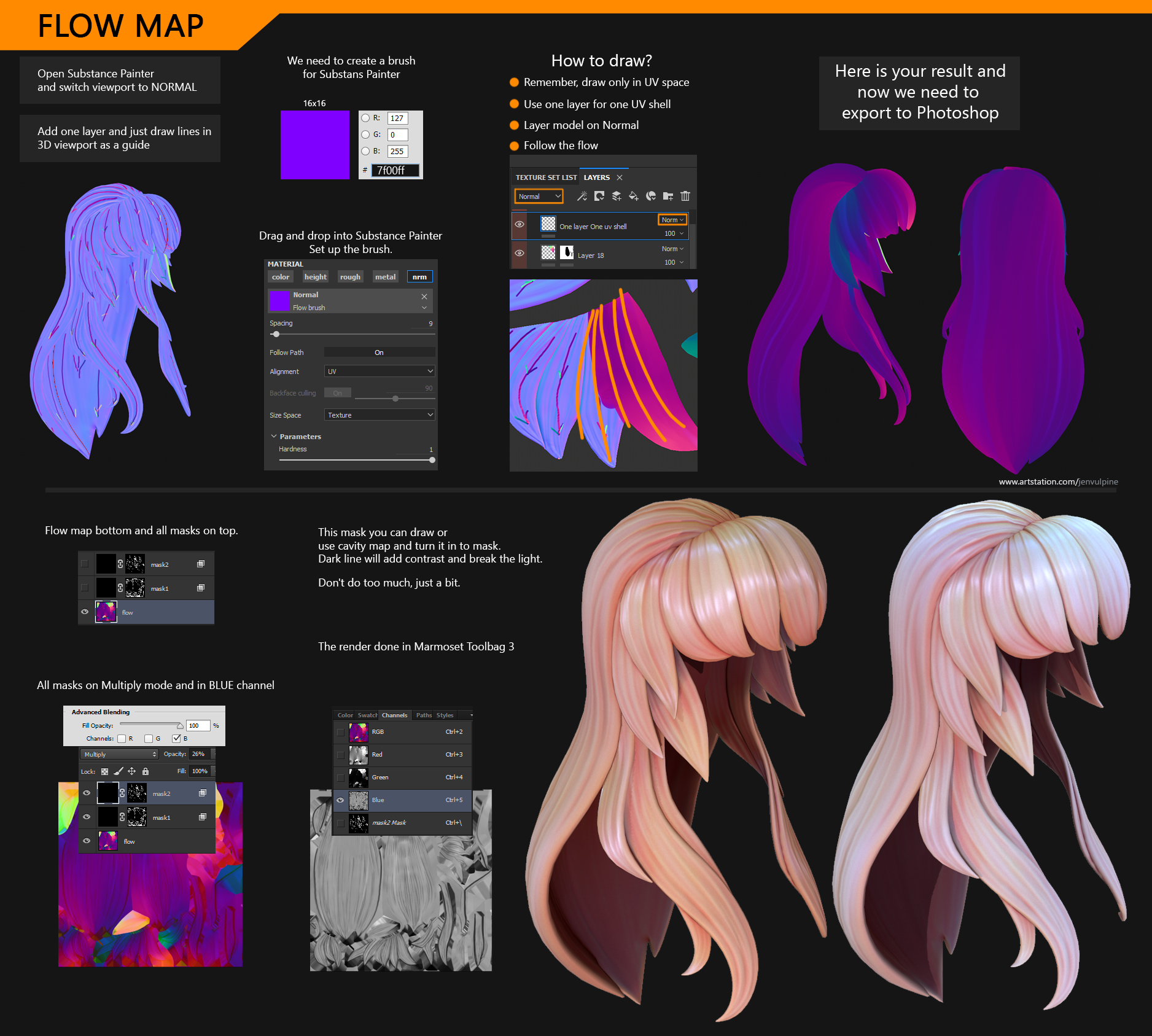
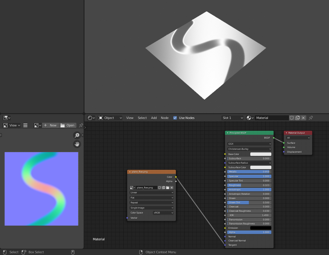
A flow map is a map of vectors. It seems to me that they ought to be in tangent space for a model like this, which can deform. And the fact that I don’t see any green in that pic, presumably Z, suggests that as well. So you compare them to your tangent vector in the same tangent space, which is just 1,0,0 IIRC, by normalizing (potentially both, dunno if Blender has a pre-normalized tangent, and flow maps are not necessarily normalized although they’re likely to be for this purpose), taking the dot product, then taking the arccosine of that, and then multiplying by -1 depending on which way the cross product of those two vectors is pointing (its either pointing to 0,0,1 or to 0,0,-1.) This gives you the angle in degrees, which is the rotation for your anisotropy-- although I believe you’d probably have to run it through a map range node to remap 0, pi to 0, 1, and might have to modulo the result as well. Would require a little experiementation to see exactly how Blender handles anisotropy rotation in the 0,1 range.
I guess it’s probably not for the math faint, not in Blender, especialyl since, like I was saying, some of the exact transformations require a little bit of experimentation, so you have to understand what you’re doing in order for that experimentation to lead to understanding. But once you had it, it would just be a single node group that you could reuse between materials.
Edit: I suppose since tangent space stuff like this is all basically 2D, you don’t need to do that dot product/cross product stuff, you could just take something like the arcsin of the X value from your normalized flow map. Maybe arccos, I can never remember.